Sign In
Upload
Manuals
Brands
Endress+Hauser Manuals
Measuring Instruments
Proline Promass E 300 HART
Endress+Hauser Proline Promass E 300 HART Manuals
Manuals and User Guides for Endress+Hauser Proline Promass E 300 HART. We have
1
Endress+Hauser Proline Promass E 300 HART manual available for free PDF download: Operating Instructions Manual
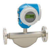
Endress+Hauser Proline Promass E 300 HART Operating Instructions Manual (212 pages)
Coriolis flowmeter
Brand:
Endress+Hauser
| Category:
Measuring Instruments
| Size: 8.77 MB
Table of Contents
Table of Contents
3
About this Document
6
Document Function
6
Symbols
6
Safety Symbols
6
Electrical Symbols
6
Communication Symbols
6
Tool Symbols
7
Symbols for Certain Types of Information
7
Symbols in Graphics
7
Documentation
8
Standard Documentation
8
Supplementary Device-Dependent Documentation
8
Registered Trademarks
8
Safety Instructions
10
Requirements for the Personnel
10
Designated Use
10
Workplace Safety
11
Operational Safety
11
Product Safety
12
Security
12
Device-Specific IT Security
12
Protecting Access Via Hardware Write Protection
12
Protecting Access Via a Password
13
Access Via Web Server
13
Access Via OPC-UA
14
Access Via Service Interface (CDI-RJ45)
14
Product Description
15
Product Design
15
Incoming Acceptance and Product
16
Identification
16
Incoming Acceptance
16
Product Identification
16
Transmitter Nameplate
17
Sensor Nameplate
18
Symbols on Measuring Device
19
Storage and Transport
20
Storage Conditions
20
Transporting the Product
20
Measuring Devices Without Lifting Lugs
20
Measuring Devices with Lifting Lugs
21
Transporting with a Fork Lift
21
Packaging Disposal
21
Installation
22
Installation Conditions
22
Mounting Position
22
Environmental and Process Requirements
24
Special Mounting Instructions
26
Mounting the Measuring Device
27
Required Tools
27
Preparing the Measuring Device
28
Mounting the Measuring Device
28
Turning the Transmitter Housing
28
Turning the Display Module
29
Post-Installation Check
29
Electrical Connection
30
Connection Conditions
30
Required Tools
30
Requirements for Connecting Cable
30
Terminal Assignment
33
Preparing the Measuring Device
33
Connecting the Measuring Device
33
Connecting the Transmitter
33
Connecting the Remote Display and Operating Module DKX001
36
Ensuring Potential Equalization
36
Requirements
36
Special Connection Instructions
37
Connection Examples
37
Ensuring the Degree of Protection
41
Post-Connection Check
41
Operation Options
42
Overview of Operation Options
42
Structure and Function of the Operating Menu
43
Structure of the Operating Menu
43
Operating Philosophy
44
Access to the Operating Menu Via the Local Display
45
Operational Display
45
Navigation View
46
Editing View
48
Operating Elements
50
Opening the Context Menu
51
Navigating and Selecting from List
52
Calling the Parameter Directly
52
Calling up Help Text
53
Changing the Parameters
53
User Roles and Related Access Authorization
54
Disabling Write Protection Via Access
54
Code
54
Enabling and Disabling the Keypad Lock
55
Access to the Operating Menu Via the Web Browser
55
Function Range
55
Prerequisites
56
Establishing a Connection
57
Logging on
59
User Interface
60
Disabling the Web Server
61
Logging out
61
Access to the Operating Menu Via the Operating Tool
62
Connecting the Operating Tool
62
Field Xpert SFX350, SFX370
65
Fieldcare
65
Devicecare
67
AMS Device Manager
67
Simatic Pdm
68
Field Communicator 475
68
System Integration
69
Overview of Device Description Files
69
Current Version Data for the Device
69
Operating Tools
69
Measured Variables Via HART Protocol
70
Device Variables
72
Other Settings
74
Commissioning
77
Function Check
77
Switching on the Measuring Device
77
Setting the Operating Language
77
Configuring the Measuring Device
77
Defining the Tag Name
79
Setting the System Units
79
Selecting and Setting the Medium
82
Displaying the I/O Configuration
83
Configuring the Current Input
84
Configuring the Status Input
85
Configuring the Current Output
86
Configuring the Pulse/Frequency
90
Switch Output
90
Configuring the Relay Output
99
10.4.10 Configuring the Double Pulse Output
102
10.4.11 Configuring the Local Display
103
10.4.12 Configuring the Low Flow Cut off
108
10.4.13 Configuring the Partial Filled Pipe Detection
109
Advanced Settings
110
Using the Parameter to Enter the Access Code
111
Calculated Values
111
Carrying out a Sensor Adjustment
112
Configuring the Totalizer
113
Carrying out Additional Display Configurations
116
WLAN Configuration
120
Configuration Management
122
Using Parameters for Device Administration
123
Simulation
124
Protecting Settings from Unauthorized Access
127
Write Protection Via Access Code
128
Write Protection Via Write Protection
129
Switch
129
Operation
131
Reading the Device Locking Status
131
Adjusting the Operating Language
131
Configuring the Display
131
Reading Measured Values
131
Measured Variables" Submenu
132
Totalizer" Submenu
133
Input Values" Submenu
134
Output Values
135
Adapting the Measuring Device to the Process
137
Conditions
137
Performing a Totalizer Reset
137
Function Scope of the "Control Totalizer" Parameter
138
Function Scope of the "Reset All Totalizers" Parameter
138
Showing Data Logging
138
Diagnostics and Troubleshooting
143
General Troubleshooting
143
Diagnostic Information Via Light Emitting
145
Diodes
145
Transmitter
145
Diagnostic Information on Local Display
147
Diagnostic Message
147
Calling up Remedial Measures
149
12.4 Diagnostic Information in the Web Browser
149
Diagnostic Options
149
Calling up Remedy Information
150
Diagnostic Information in Fieldcare or
151
Diagnostic Options
151
Calling up Remedy Information
152
Adapting the Diagnostic Information
152
Adapting the Diagnostic Behavior
152
Adapting the Status Signal
152
Overview of Diagnostic Information
153
Pending Diagnostic Events
157
Diagnostic List
158
12.10 Event Logbook
159
12.10.1 Reading out the Event Logbook
159
12.10.2 Filtering the Event Logbook
160
12.10.3 Overview of Information Events
160
12.11 Resetting the Measuring Device
161
12.11.1 Function Scope of the "Device Reset" Parameter
162
12.12 Device Information
162
12.13 Firmware History
164
12.14 Device History and Compatibility
166
Maintenance
167
Maintenance Tasks
167
Exterior Cleaning
167
Interior Cleaning
167
Measuring and Test Equipment
167
Endress+Hauser Services
167
Repair
168
General Notes
168
Repair and Conversion Concept
168
Notes for Repair and Conversion
168
Spare Parts
168
Endress+Hauser Services
168
Return
168
Disposal
169
Removing the Measuring Device
169
Disposing of the Measuring Device
169
Accessories
170
Device-Specific Accessories
170
For the Transmitter
170
For the Sensor
171
Communication-Specific Accessories
171
Service-Specific Accessories
172
System Components
172
Technical Data
173
Application
173
Function and System Design
173
Input
174
Output
177
Power Supply
183
Performance Characteristics
184
Installation
188
Environment
188
Process
189
16.10 Mechanical Construction
191
16.11 Human Interface
194
16.12 Certificates and Approvals
199
16.13 Application Packages
201
16.14 Accessories
203
Supplementary Documentation
203
Index
205
Advertisement
Advertisement
Related Products
Endress+Hauser Proline Promass E 300
Endress+Hauser Proline Promass E 200
Endress+Hauser Proline Promass E 100
Endress+Hauser Analytik Jena multi EA 5000
Endress+Hauser Analytik Jena multi EA 5100
Endress+Hauser Liquiline To Go Ex CYM291
Endress+Hauser Endress+Hauser
Endress+Hauser Proline Promass E 500 PROFINET
Endress+Hauser Proline Prosonic Flow E 100 HART
Endress+Hauser Proline Promass E TB2 HART
Endress+Hauser Categories
Measuring Instruments
Transmitter
Radar
Switch
Accessories
More Endress+Hauser Manuals
Login
Sign In
OR
Sign in with Facebook
Sign in with Google
Upload manual
Upload from disk
Upload from URL