Sign In
Upload
Manuals
Brands
Emerson Manuals
Transmitter
Rosemount Analytical Oxymitter 4000
Emerson Rosemount Analytical Oxymitter 4000 Manuals
Manuals and User Guides for Emerson Rosemount Analytical Oxymitter 4000. We have
1
Emerson Rosemount Analytical Oxymitter 4000 manual available for free PDF download: Instruction Manual
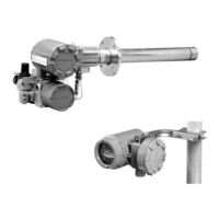
Emerson Rosemount Analytical Oxymitter 4000 Instruction Manual (150 pages)
HAZARDOUS AREA OXYGEN TRANSMITTER
Brand:
Emerson
| Category:
Transmitter
| Size: 4.68 MB
Table of Contents
Table of Contents
5
Preface
9
Definitions
9
Safety Instructions
10
Description and Specifications
31
Component Checklist of Typical System (Package Contents)
31
System Overview
31
Figure 1-1. Typical System Package
32
Figure 1-2. Hazardous Area Oxymitter 4000 Autocalibration System Options
33
Figure 1-3. Membrane Keypad
34
Figure 1-4. Local Operator Interface (LOI)
34
Figure 1-5. Hazardous Area Oxymitter 4000 HART Connections and AMS Application
36
Figure 1-6. Typical System Installation - Oxymitter 4000 with Integral Electronics
37
Figure 1-7. Typical System Installation - Oxymitter 4000 with Remote Electronics
38
IMPS 4000 (Optional)
39
SPS 4000 (Optional)
39
Model 751 Remote Powdered Loop LCD Display
39
Figure 1-8. Model 751 Remote Powered Loop LCD Display
39
Probe Options
40
Figure 1-9. Flame Arrestor Ceramic Diffusion Assembly
40
Figure 1-10. Flame Arrestor Snubber Diffusion Assembly
40
Figure 1-11. Abrasive Shield Assembly
41
Specifications
42
Hazardous Area Certifications
43
Table 1-1. Product Matrix
44
Table 1-2. Calibration Components
46
Table 1-3. Intelligent Multiprobe Test Gas Sequencer Versions
46
Installation
47
Mechanical Installation
47
Figure 2-1. Hazardous Area Oxymitter 4000 Probe Installation
48
Figure 2-2. Hazardous Area Oxymitter 4000 Remote Electronics Installation
49
Figure 2-3. Hazardous Area Oxymitter 4000 Probe with Abrasive Shield
50
Figure 2-4. Hazardous Area Oxymitter 4000 Mounting Plate Dimensions
51
Figure 2-5. Hazardous Area Oxymitter 4000 Mounting Plate Installation
52
Figure 2-6. Orienting the Optional Vee Deflector
53
Electrical Installation (for Hazardous Area Oxymitter 4000 with Integral Electronics)
54
Figure 2-7. Installation with Drip Loop and Insulation Removal
54
Figure 2-8. Remote Electronics Mounting
54
Figure 2-9. Electrical Installation - Hazardous Area Oxymitter 4000 with Integral Electronics
56
Electrical Installation (for Hazardous Area Oxymitter 4000 with Remote Electronics)
57
Figure 2-10. Electrical Installation - Hazardous Area Oxymitter 4000 with Remote Electronics
58
Pneumatic Installation
60
IMPS 4000 Connections
61
SPS 4000 Connections
61
Figure 2-11. Air Set, Plant Air Connection
61
Figure 2-12. Hazardous Area Oxymitter 4000 Gas Connections
61
Configuration of Hazardous Area Oxymitter 4000 with Membrane Keypad
63
General
63
Figure 3-1. Electronics Housing Terminals and Membrane Keypad
63
Figure 3-2. Defaults - Hazardous Area Oxymitter 4000 with Membrane Keypad
65
Logic I/O
66
Recommended Configuration
67
Configuration of Hazardous Area Oxymitter 4000 with Loi
69
General
69
Figure 4-1. Electronics Housing Terminals with LOI
69
Figure 4-2. Defaults - Hazardous Area Oxymitter 4000 with LOI
71
Logic I/O
72
Recommended Configuration
73
Startup and Operation of Hazardous Area Oxymitter 4000 with Membrane Keypad
75
Power up
75
Figure 5-1. Startup and Normal Operation
75
Operation
76
Figure 5-2. Calibration Keys
76
IB-106-340C Rev. 4.1
77
Figure 5-3. Normal Operation
77
Startup and Operation of Hazardous Area Oxymitter 4000 with Loi
79
Power up
79
Start up Oxymitter 4000 Calibration
79
Figure 6-1. Startup Display
79
Figure 6-2. Normal Display
79
Navigating the Local Operator Interface
80
LOI Key Designations
80
Figure 6-3. LOI Features
80
LOI Menu Tree
81
Figure 6-4. Local Operator Interface Menu Tree (Sheet 1 of 2)
81
LOI Installation
84
Figure 6-5. LOI Module Connectors
84
Oxymitter 4000 Test Points
85
Model 751 Remote Powered Loop LCD Display (Optional)
85
Figure 6-6. Test Points
85
Hart/Ams
87
Overview
87
HART Communicator Signal Line Connections
87
Figure 7-1. Signal Line Connections, ≥ 250 Ohms Load Resistance
88
HART Communicator PC Connections
89
Off-Line and On-Line Operations
89
Figure 7-2. Signal Line Connections, < 250 Ohms Load Resistance
89
Logic I/O Configurations
90
HART/AMS Menu Tree for Hazardous Area Oxymitter 4000 Applications
90
Table 7-1. Logic I/O Configuration (as Set at HART/AMS or LOI)
90
Figure 7-3. HART/AMS Menu Tree (Sheet 1 of 3)
91
HART Communicator OCAL Method
94
Troubleshooting
97
Overview
97
General
98
Alarm Indications
98
Figure 8-2. Diagnostic Leds
98
Alarm Contacts
99
Identifying and Correcting Alarm Indications
99
Table 8-1. Diagnostic/Unit Alarm Fault Definitions - Membrane Keypad Only
100
Table 8-2. Diagnostic/Unit Alarm Fault Definitions - LOI
100
Figure 8-3. Fault 1, Open Thermocouple
101
Figure 8-4. Fault 2, Shorted Thermocouple
102
Figure 8-5. Fault 3, Reversed Thermocouple
103
Figure 8-6. Fault 4, A/D Comm Error
104
Figure 8-7. Fault 5, Open Heater
105
Figure 8-8. Fault 6, High High Heater Temp
106
Figure 8-9. Fault 7, High Case Temp
107
Figure 8-10. Fault 8, Low Heater Temp
108
Figure 8-11. Fault 9, High Heater Temp
109
Figure 8-12. Fault 10, High Cell MV
110
Figure 8-13. Fault 11, Bad Cell
111
Figure 8-14. Fault 12, Eeprom Corrupt
112
Figure 8-15. Fault 13, Invalid Slope
113
Figure 8-16. Fault 14, Invalid Constant
114
Figure 8-17. Fault 15, Last Calibration Failed
115
Hazardous Area Oxymitter 4000 Passes Calibration, but Still Reads Incorrectly
116
Figure 8-18. Probe Leakage Paths
116
Maintenance and Service
119
Overview
119
Calibration - Hazardous Area Oxymitter 4000 with Keypad
119
Figure 9-1. Membrane Keypad
120
Figure 9-2. Inside Right Cover
122
Calibration - Hazardous Area Oxymitter 4000 with LOI
123
Hazardous Area Oxymitter 4000 Repair
125
Figure 9-3. Hazardous Area Oxymitter 4000 with Integral Electronics - Exploded View
126
Figure 9-4. Hazardous Area Oxymitter 4000 with Remote Electronics - Exploded View
127
Figure 9-5. Electronic Assembly
128
Figure 9-6. J8 Connector
129
Figure 9-7. Fuse Location
130
Figure 9-8. Heater Strut Assembly
132
Figure 9-9. Cell Replacement Kit
133
Figure 9-10. Ceramic Diffuser Element Replacement
134
Figure 9-11. Contact and Thermocouple Assembly Replacement
136
Return of Material
137
Replacement Parts
139
Table 11-1. Replacement Parts for Probe
139
Figure 11-1. Cell Replacement Kit
140
Figure 11-2. Probe Disassembly Kit
141
Table 11-2. Replacement Parts for Electronics
142
Optional Accessories
143
Index
147
Advertisement
Advertisement
Related Products
Emerson Rosemount
Emerson Rosemount 3051 Series
Emerson Rosemount 2051 Wireless Series
Emerson Rosemount Ultrasonic 3108
Emerson Rosemount X-well 648
Emerson Rosemount 644 FOUNDATION
Emerson Rosemount HART Modbus VeriCase 3308 Series
Emerson Rosemount HART Modbus VeriCase 5300 Series
Emerson Rosemount 702 Series
Emerson Rosemount 520
Emerson Categories
Controller
Control Unit
Transmitter
Measuring Instruments
Fan
More Emerson Manuals
Login
Sign In
OR
Sign in with Facebook
Sign in with Google
Upload manual
Upload from disk
Upload from URL