Sign In
Upload
Manuals
Brands
Elektro-Automatik Manuals
Power Supply
EL 9000 B 15U Series
Elektro-Automatik EL 9000 B 15U Series Manuals
Manuals and User Guides for Elektro-Automatik EL 9000 B 15U Series. We have
3
Elektro-Automatik EL 9000 B 15U Series manuals available for free PDF download: Operating Manual
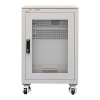
Elektro-Automatik EL 9000 B 15U Series Operating Manual (172 pages)
Electronic DC load
Brand:
Elektro-Automatik
| Category:
Power Supply
| Size: 4 MB
Table of Contents
Deutsch
3
Table of Contents
3
Allgemeines
5
Aufbewahrung und Verwendung
5
Geltungsbereich
5
Gewährleistung und Garantie
5
Haftungsbeschränkungen
5
Symbole und Hinweise
5
Urheberschutz (Copyright)
5
Zu diesem Dokument
5
Bestimmungsgemäße Verwendung
6
Entsorgung des Gerätes
6
Produktschlüssel
6
Sicherheit
7
Sicherheitshinweise
7
Anforderungen an das Bedienpersonal
8
Pflichten Des Betreibers
8
Verantwortung des Bedieners
8
Alarmsignale
9
Bedieneinheit
9
Technische Daten
9
Zulässige Betriebsbedingungen
9
Ansichten
13
Bedienelemente
17
Allgemeine Beschreibung
18
Aufbau und Funktion
18
Blockdiagramm
18
Lieferumfang
19
Optionen
19
Zubehör
19
Die Bedieneinheit (HMI)
20
Analogschnittstelle
23
Steckplatz für Schnittstellenmodule
23
USB-Port Typ B (Rückseite)
23
Master-Slave-Bus
24
Installation & Inbetriebnahme
25
Sense-Anschluß (Fernfühlung)
24
Share-Bus-Anschluß
24
Auspacken und Sichtkontrolle
25
Lagerung
25
Sicherheitsmaßnahmen vor Installation und Gebrauch
25
Transport
25
Transport und Lagerung
25
Aufstellung des Gerätes
26
Vorbereitung
26
Anschließen an das Stromnetz (AC)
27
Anschließen von DC-Quellen
28
Anschließen der Fernfühlung
30
Anschließen des „Share-Bus
30
Erdung des DC-Eingangs
30
Anschließen der Analogen Schnittstelle
31
Installation eines Schnittstellenmoduls
31
Anschließen des USB-Ports (Rückseite)
32
Entnahme von Einheiten
32
Erneute Inbetriebnahme nach Firmwareupdates Bzw. Längerer Nichtbenutzung
32
Erstinbetriebnahme
32
Einsetzen von Einheiten
33
Hinzufügen von Neuen Einheiten
33
Not-Aus
33
Bedienung und Verwendung
34
Personenschutz
34
Regelungsarten
34
Spannungsregelung / Konstantspannung
34
Leistungsregelung / Konstantleistung / Leistungsbegrenzung
35
Stromregelung / Konstantstrom / Strombegrenzung
35
Widerstandsregelung/Konstantwiderstand
35
Regelverhalten und Stabilitätskriterium
36
Alarmzustände
37
Power Fail
37
Überleistung (Overpower)
37
Überspannung (Overvoltage)
37
Überstrom (Overcurrent)
37
Übertemperatur (Overtemperature)
37
Ausschalten des Gerätes
38
Einschalten des Gerätes
38
Konfiguration IM Menu
38
Manuelle Bedienung
38
Bedienart Wechseln
48
Einstellgrenzen (Limits)
48
Sollwerte Manuell Einstellen
49
Ansichtsmodus der Hauptanzeige Wechseln
50
Die Meßleisten
50
Datenaufzeichnung auf USB-Stick (Logging)
51
DC-Eingang Ein- oder Ausschalten
51
Allgemeines
53
Bedienorte
53
Fernsteuerung
53
Fernsteuerung über eine Digitale Schnittstelle
53
Fernsteuerung über Analogschnittstelle (AS)
54
Alarme und Überwachung
58
Begriffsdefinition
58
Gerätealarme und Events Handhaben
58
Bedieneinheit (HMI) Sperren
61
Einstellgrenzen (Limits) Sperren
61
Nutzerprofile Laden und Speichern
62
Allgemeines
63
Der Funktionsgenerator
63
Einleitung
63
Arbeitsweise
64
Manuelle Bedienung
64
Sinus-Funktion
65
Dreieck-Funktion
66
Rechteck-Funktion
66
DIN 40839-Funktion
67
Trapez-Funktion
67
3.10.10 Arbiträr-Funktion
68
3.10.11 Rampen-Funktion
72
UI- und IU-Tabellenfunktion (XY-Tabelle)
72
3.10.13 Batterietest-Funktion
74
3.10.14 MPP-Tracking-Funktion
76
3.10.15 Fernsteuerung des Funktionsgenerators
78
Besonderheiten Beim Master-Slave-Betrieb
80
Weitere Informationen
80
Weitere Anwendungen
80
Defekte Netzsicherung Tauschen
81
Fehlersuche / Fehlerdiagnose / Reparatur
81
Wartung / Reinigung
81
Firmware-Aktualisierungen
82
Einleitung
83
Nachjustierung (Kalibrierung)
83
Vorbereitung
83
Abgleichvorgang
84
Instandhaltung & Wartung
81
Parallelschaltung
80
Reihenschaltung
80
Service & Support
85
Kontaktmöglichkeiten
85
English
89
General
91
Reparaturen
85
About this Document
91
Copyright
91
Limitation of Liability
91
Retention and Use
91
Symbols and Warnings
91
Validity
91
Warranty
91
Disposal of Equipment
92
Intended Usage
92
Product Key
92
Safety
93
Safety Notices
93
Responsibility of the Operator
94
Responsibility of the User
94
User Requirements
94
Alarm Signals
95
Approved Operating Conditions
95
Control Panel
95
Technical Data
95
Technical Specifications
95
Views
99
Control Elements
103
Block Diagram
104
Construction and Function
104
General Description
104
Accessories
105
Options
105
Scope of Delivery
105
The Control Panel (HMI)
106
Analog Interface
109
Interface Module Slot
109
USB Port Type B (Rear Side)
109
Master-Slave Bus
110
Installation & Commissioning
111
Sense" Connector (Remote Sensing)
110
Share Bus Connector
110
Installation
111
Preparation
111
Safety Procedures before Installation and Use
111
Storage
111
Transport
111
Transport and Storage
111
Unpacking and Visual Check
111
Installing the Device
112
Connection to AC Supply
113
Connection to DC Sources
114
Connecting the "Share" Bus
116
Connection of Remote Sense
116
Grounding of the DC Input
116
Connecting the Analog Interface
117
Connecting the USB Port (Rear Side)
117
Installation of an Interface Module
117
Commission after a Firmware Update or a Long Period of Non-Use
118
Initial Commission
118
Inserting Units
118
Removing Units
118
Adding New Units
119
Emergency Stop
119
Operating Modes
120
Operation and Application
120
Personal Safety
120
Voltage Regulation / Constant Voltage
120
Current Regulation / Constant Current / Current Limiting
121
Power Regulation / Constant Power / Power Limitation
121
Resistance Regulation / Constant Resistance
121
Dynamic Characteristics and Stability Criteria
122
Alarm Conditions
123
Overcurrent Protection
123
Overpower Protection
123
Overtemperature
123
Overvoltage Protection
123
Power Fail
123
Configuration Via MENU
124
Manual Operation
124
Switching off the Device
124
Switching on the Device
124
Adjustment Limits
134
Changing the Operating Mode
134
Manual Adjustment of Set Values
135
Switching the Main Screen View
135
Switching the DC Input on or off
136
The Meter Bars
136
Recording to USB Stick (Logging)
137
Control Locations
138
General
138
Remote Control
138
Remote Control Via a Digital Interface
138
Remote Control Via the Analog Interface (AI)
139
Alarms and Monitoring
143
Definition of Terms
143
Device Alarm and Event Handling
143
Control Panel (HMI) Lock
146
Limits Lock
146
Loading and Saving a User Profile
147
General
148
Introduction
148
The Function Generator
148
Manual Operation
149
Method of Operation
149
Sine Wave Function
150
Rectangular Function
151
Triangular Function
151
DIN 40839 Function
152
Trapezoidal Function
152
3.10.10 Arbitrary Function
153
3.10.11 Ramp Function
157
UI and IU Table Functions (XY Table)
157
3.10.13 Battery Test Function
159
3.10.14 MPP Tracking Function
161
3.10.15 Remote Control of the Function Generator
163
Other Applications
164
Parallel Operation in Master-Slave (MS)
164
Series Connection
164
Other Information
164
Special Characteristics of Master-Slave Operation
164
Service and Maintenance
165
Fault Finding / Diagnosis / Repair
165
Maintenance / Cleaning
165
Replacing a Defect Mains Fuse
165
Firmware Updates
166
Calibration
167
Calibration Procedure
167
Contact and Support
169
Preface
167
Preparation
167
Repairs
169
Advertisement
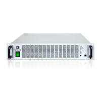
Elektro-Automatik EL 9000 B 15U Series Operating Manual (102 pages)
Electronic DC Load
Brand:
Elektro-Automatik
| Category:
Test Equipment
| Size: 1 MB
Table of Contents
Deutsch
3
Table of Contents
3
Zu diesem Dokument
4
Aufbewahrung und Verwendung
4
Urheberschutz (Copyright)
4
Geltungsbereich
4
Symbole und Hinweise
4
Gewährleistung und Garantie
4
Haftungsbeschränkungen
4
Entsorgung des Gerätes
5
Produktschlüssel
5
Bestimmungsgemäße Verwendung
5
Sicherheit
6
Sicherheitshinweise
6
Verantwortung des Bedieners
6
Pflichten des Betreibers
7
Anforderungen an das Bedienpersonal
7
Alarmsignale
8
Technische Daten
8
Zulässige Betriebsbedingungen
8
Allgemeine Technische Daten
8
Spezifische Technische Daten
9
Ansichten
13
Bedienelemente
16
Aufbau und Funktion
17
Allgemeine Beschreibung
17
Blockdiagramm
17
Lieferumfang
18
Zubehör
18
Die Bedieneinheit (HMI)
19
USB-Port Typ B (Rückseite)
19
Steckplatz für Schnittstellenmodule
20
Analogschnittstelle
20
Share-Bus-Anschluß
20
Sense-Anschluß (Fernfühlung)
21
Master-Slave-Bus
21
Installation & Inbetriebnahme
22
Transport und Lagerung
22
Transport
22
Verpackung
22
Lagerung
22
Auspacken und Sichtkontrolle
22
Installation
22
Sicherheitsmaßnahmen vor Installation und Gebrauch
22
Vorbereitung
23
Aufstellung des Gerätes
23
Anschließen von DC-Quellen
24
Erdung des DC-Eingangs
25
Anschließen des „Share-Bus
25
Anschließen der Fernfühlung
25
Anschließen der USB-Ports
26
Installation eines Schnittstellenmoduls
26
Anschließen der Analogen Schnittstelle
27
Erstinbetriebnahme
27
Erneute Inbetriebnahme nach Firmwareupdates Bzw. Längerer Nichtbenutzung
27
Bedienung und Verwendung
28
Personenschutz
28
Regelungsarten
28
Spannungsregelung / Konstantspannung
28
Leistungsregelung / Konstantleistung / Leistungsbegrenzung
29
Stromregelung / Konstantstrom / Strombegrenzung
29
Widerstandsregelung/Konstantwiderstand
29
Regelverhalten und Stabilitätskriterium
30
Alarmzustände
31
Power Fail
31
Überleistung (Overpower)
31
Überspannung (Overvoltage)
31
Überstrom (Overcurrent)
31
Übertemperatur (Overtemperature)
31
Ausschalten des Gerätes
32
DC-Eingang Ein- oder Ausschalten
32
Einschalten des Gerätes
32
Manuelle Bedienung
32
Allgemeines
33
Fernsteuerung
33
Fernsteuerung über den Hinteren USB-Port oder ein Schnittstellen-Modul
33
Fernsteuerung über den Vorderen USB-Port
34
Fernsteuerung über Analogschnittstelle (AS)
35
Alarme und Überwachung
39
Begriffsdefinition
39
Gerätealarme und Events Handhaben
39
Anwendungen
41
Zwei-Quadranten-Betrieb (2QB)
41
Parallelschaltung als Master-Slave (MS)
44
Instandhaltung & Wartung
48
Reihenschaltung
44
Defekte Netzsicherung Tauschen
48
Fehlersuche / Fehlerdiagnose / Reparatur
48
Firmware-Aktualisierungen
48
Service & Support
49
Wartung / Reinigung
48
Kontaktmöglichkeiten
49
Reparaturen
49
English
55
About this Document
56
Copyright
56
Limit of Liability
56
Retention and Use
56
Symbols and Warnings
56
Validity
56
Warranty
56
Disposal of Equipment
57
Intended Usage
57
Product Key
57
Responsibility of the User
58
Safety
58
Safety Notices
58
Responsibility of the Operator
59
User Requirements
59
Alarm Signals
60
Approved Operating Conditions
60
General Technical Data
60
Technical Data
60
Specific Technical Data
61
Views
65
Control Elements
68
Block Diagram
69
Construction and Function
69
General Description
69
Accessories
70
Scope of Delivery
70
The Control Panel (HMI)
71
USB-Port Type B (Back Side)
71
Analog Interface
72
Interface Module Slot
72
Share" Connector
72
Master-Slave Bus
73
Sense" Connector (Remote Sensing)
73
Installation & Commissioning
74
Installation
74
Packaging
74
Safety Procedures before Installation and Use
74
Storage
74
Transport
74
Transport and Storage
74
Unpacking and Visual Check
74
Installing the Device
75
Preparation
75
Connection to DC Sources
76
Connecting the "Share" Bus
77
Connection of Remote Sensing
77
Grounding of the DC Input
77
Connecting the USB Ports
78
Installation of an Interface Module
78
Commission after a Firmware Update or a Long Period of Non-Use
79
Operation and Application
80
Connecting the Analog Interface
79
Initial Commission
79
Operating Modes
80
Personal Safety
80
Voltage Regulation / Constant Voltage
80
Current Regulation / Constant Current / Current Limitation
81
Power Regulation / Constant Power / Power Limitation
81
Resistance Regulation / Constant Resistance
81
Dynamic Characteristics and Stability Criteria
82
Alarm Conditions
83
Overcurrent
83
Overpower
83
Overtemperature
83
Overvoltage
83
Power Fail
83
Manual Operation
84
Powering the Device
84
Switching the DC Input on or off
84
Switching the Device off
84
General
85
Remote Control
85
Remote Control Via the Rear USB Port or Interface Module
85
Remote Control Via the Front USB
86
Remote Control Via the Analog Interface (AI)
87
Alarms and Monitoring
91
Definition Of Terms
91
Device Alarm and Event Handling
91
Other Applications
93
Two Quadrants Operation (2QO)
93
Parallel Operation in Master-Slave (MS)
96
Service and Maintenance
99
Series Connection
96
Fault Finding / Diagnosis / Repair
99
Firmware Updates
99
Contact and Support
100
Maintenance / Cleaning
99
Replacing a Defect Mains Fuse
99
Contact Options
100
Repairs
100
Elektro-Automatik EL 9000 B 15U Series Operating Manual (84 pages)
Electronic DC Load
Brand:
Elektro-Automatik
| Category:
Power Supply
| Size: 3 MB
Table of Contents
Table of Contents
3
General
5
About this Document
5
Retention and Use
5
Copyright
5
Validity
5
Symbols and Warnings
5
Warranty
5
Limitation of Liability
5
Disposal of Equipment
6
Product Key
6
Intended Usage
6
Safety
7
Safety Notices
7
Responsibility of the User
8
Responsibility of the Operator
8
User Requirements
8
Alarm Signals
9
Technical Data
9
Approved Operating Conditions
9
Control Panel
9
Technical Specifications
9
Views
13
Control Elements
17
Construction and Function
18
General Description
18
Block Diagram
18
Scope of Delivery
19
Accessories
19
Options
19
The Control Panel (HMI)
20
USB Port Type B (Rear Side)
23
Interface Module Slot
23
Analog Interface
23
Share Bus Connector
24
Sense" Connector (Remote Sensing)
24
Master-Slave Bus
24
Installation & Commissioning
25
Transport and Storage
25
Transport
25
Storage
25
Unpacking and Visual Check
25
Installation
25
Safety Procedures before Installation and Use
25
Preparation
25
Installing the Device
26
Connection to AC Supply
27
Connection to DC Sources
28
Grounding of the DC Input
30
Connecting or Extending the "Share" Bus
30
Connection of Remote Sense
30
Installation of an Interface Module
31
Connecting the Analog Interface
31
Connecting the USB Port (Rear Side)
31
Initial Commission
32
Commission after a Firmware Update or a Long Period of Non-Use
32
Removing Units
32
Inserting Units
32
Adding New Units
33
Emergency Stop
33
Operation and Application
34
Personal Safety
34
Operating Modes
34
Voltage Regulation / Constant Voltage
34
Current Regulation / Constant Current / Current Limiting
35
Resistance Regulation / Constant Resistance
35
Power Regulation / Constant Power / Power Limitation
35
Dynamic Characteristics and Stability Criteria
36
Alarm Conditions
37
Power Fail
37
Overtemperature
37
Overvoltage Protection
37
Overcurrent Protection
37
Overpower Protection
37
Manual Operation
38
Switching on the Device
38
Switching off the Device
38
Configuration Via MENU
38
Adjustment Limits
45
Changing the Operating Mode
45
Manual Adjustment of Set Values
46
Switching the Main Screen View
46
The Meter Bars
47
Switching the DC Input on or off
47
Recording to USB Stick (Logging)
48
Remote Control
49
General
49
Control Locations
49
Remote Control Via a Digital Interface
49
Remote Control Via the Analog Interface (AI)
51
Alarms and Monitoring
55
Definition of Terms
55
Device Alarm and Event Handling
55
Control Panel (HMI) Lock
58
Limits Lock
58
Loading and Saving a User Profile
59
Www.elektroautomatik.de
59
Ea1974@Elektroautomatik.de
59
The Function Generator
60
Introduction
60
General
60
Method of Operation
61
Manual Operation
61
Sine Wave Function
62
Triangular Function
63
Rectangular Function
63
Trapezoidal Function
64
DIN 40839 Function
64
Arbitrary Function
65
Ramp Function
69
UI and IU Table Functions (XY Table)
69
Battery Test Function
71
MPP Tracking Function
73
Remote Control of the Function Generator
76
Other Applications
77
Parallel Operation in Master-Slave (MS)
77
Series Connection
77
Other Information
77
Special Characteristics of Master-Slave Operation
77
Service and Maintenance
78
Maintenance / Cleaning
78
Fault Finding / Diagnosis / Repair
78
Replacing a Defect Mains Fuse
78
Firmware Updates
79
Calibration
80
Preface
80
Preparation
80
Calibration Procedure
80
Contact and Support
82
Repairs
82
Contact Options
82
Advertisement
Advertisement
Related Products
Elektro-Automatik EL 9000 B 24U
Elektro-Automatik EL 9000 HP Series
Elektro-Automatik EL 9000 DT Series
Elektro-Automatik EL 9000 A
Elektro-Automatik EL 9000 HP
Elektro-Automatik EL 9080-1530 B 15U
Elektro-Automatik EL 9080-2040 B 24U
Elektro-Automatik EL 9080-2550 B 24U
Elektro-Automatik EL 9080-600 HP
Elektro-Automatik EL 9080-45 DT
Elektro-Automatik Categories
Power Supply
UPS
Enclosure
Test Equipment
Computer Hardware
More Elektro-Automatik Manuals
Login
Sign In
OR
Sign in with Facebook
Sign in with Google
Upload manual
Upload from disk
Upload from URL