Elektro-Automatik EL 9000 B 2Q Series Operating Manual
Electronic dc load
Hide thumbs
Also See for EL 9000 B 2Q Series:
- Operating manual (172 pages) ,
- Operating manual (84 pages)
Table of Contents
Advertisement
Available languages
Available languages
Quick Links
Advertisement
Chapters
Table of Contents

Related Manuals for Elektro-Automatik EL 9000 B 2Q Series


Summary of Contents for Elektro-Automatik EL 9000 B 2Q Series
- Page 1 Betriebsanleitung EL 9000 B 2Q Elektronische DC-Last Doc ID: EL9QDE Revision: 01 Date: 05/2017 Distributed by: dataTec ▪ Ferdinand-Lassalle-Str. 52 ▪ 72770 Reutlingen ▪ Tel. 07121 / 51 50 50 ▪ Fax 07121 / 51 50 10 ▪ info@datatec.de ▪ www.datatec.de...
-
Page 3: Table Of Contents
Anschließen der Fernfühlung ......25 Kontaktmöglichkeiten ........49 2.3.8 Anschließen der USB-Ports ......26 2.3.9 Installation eines Schnittstellenmoduls ..26 2.3.10 Anschließen der analogen Schnittstelle ..27 EA Elektro-Automatik GmbH Telefon: 02162 / 3785-0 www.elektroautomatik.de Seite 3 Helmholtzstr. 31-37 • 41747 Viersen Telefax: 02162 / 16230 ea1974@elektroautomatik.de... -
Page 4: Zu Diesem Dokument
Hinweissymbol für allgemeine Sicherheitshinweise (Gebote und Verbote zur Schadensverhütung) Allgemeiner Hinweis Gewährleistung und Garantie Elektro-Automatik garantiert die Funktionsfähigkeit der Geräte im Rahmen der ausgewiesenen Leistungsparameter. Die Gewährleistungsfrist beginnt mit der mängelfreien Übergabe. Die Garantiebestimmungen sind den allgemeinen Geschäftsbedingungen (AGB) der EA Elektro-Automatik GmbH entnehmen. -
Page 5: Entsorgung Des Gerätes
Ein Gerät, das zur Entsorgung vorgesehen ist, muß laut europaweit geltenden Gesetzen und Verordnungen (Elek- troG, WEEE) von Elektro-Automatik zurückgenommen und entsorgt werden, sofern der Betreiber des Gerätes oder ein von ihm Beauftragter das nicht selbst erledigt. Unsere Geräte unterliegen diesen Verordnungen und sind dementsprechend mit diesem Symbol gekennzeichnet: Produktschlüssel... -
Page 6: Sicherheit
• vor Arbeitsbeginn die Betriebsanleitung vollständig gelesen und verstanden haben. • die vorgeschriebenen und empfohlenen Schutzausrüstungen anwenden. Weiterhin ist jeder an dem Gerät Beschäftigte in seinem Zuständigkeitsumfang dafür verantwortlich, daß das Gerät stets in technisch einwandfreiem Zustand ist. EA Elektro-Automatik GmbH Telefon: 02162 / 3785-0 www.elektroautomatik.de Seite 6 Helmholtzstr. -
Page 7: Pflichten Des Betreibers
Gefahren ausführlich und nachweislich unterrichtet wurden. Als Fachpersonal gilt, wer aufgrund seiner beruflichen Ausbildung, Kenntnisse und Erfahrungen sowie Kenntnis der einschlägigen Bestimmungen in der Lage ist, die übertragenen Arbeiten ordnungsgemäß auszuführen, mög- liche Gefahren selbständig zu erkennen und Personen- oder Sachschäden zu vermeiden. EA Elektro-Automatik GmbH Telefon: 02162 / 3785-0 www.elektroautomatik.de Seite 7 Helmholtzstr. -
Page 8: Alarmsignale
1.8.2 Allgemeine technische Daten Anzeigeart: 6x farbige LEDs Bedienelemente: 1 Drucktaste Die Nennwerte des Gerätes bestimmen den maximal einstellbaren Bereich. EA Elektro-Automatik GmbH Telefon: 02162 / 3785-0 www.elektroautomatik.de Seite 8 Helmholtzstr. 31-37 • 41747 Viersen Telefax: 02162 / 16230 ea1974@elektroautomatik.de... -
Page 9: Spezifische Technische Daten
Beispiel: das 85 A-Modell hat min. 0,2% Stromgenauigkeit, das ergibt 170 mA max. zulässige Abweichung. Bei einem Sollwert von 10 A dürfte der Istwert also 9,83 A...10,17 A betragen. (2 Bis zu 30°C Umgebungstemperatur, darüber hinaus konstantes Derating (3 Technische Daten der Analogschnittstelle siehe „3.5.4.4 Spezifikation der Analogschnittstelle“ auf Seite 36 EA Elektro-Automatik GmbH Telefon: 02162 / 3785-0 www.elektroautomatik.de Seite 9 Helmholtzstr. - Page 10 ~ 9 kg ~ 9 kg ~ 9 kg ~ 9 kg ~ 9 kg Artikelnummer 33200710 33200711 33200712 33200713 33200714 EA Elektro-Automatik GmbH Telefon: 02162 / 3785-0 www.elektroautomatik.de Seite 10 Helmholtzstr. 31-37 • 41747 Viersen Telefax: 02162 / 16230 ea1974@elektroautomatik.de...
- Page 11 Beispiel: das 85 A-Modell hat min. 0,2% Stromgenauigkeit, das ergibt 170 mA max. zulässige Abweichung. Bei einem Sollwert von 10 A dürfte der Istwert also 9,83 A...10,17 A betragen. (2 Bis zu 30°C Umgebungstemperatur, darüber hinaus konstantes Derating (3 Technische Daten der Analogschnittstelle siehe „3.5.4.4 Spezifikation der Analogschnittstelle“ auf Seite 36 EA Elektro-Automatik GmbH Telefon: 02162 / 3785-0 www.elektroautomatik.de Seite 11 Helmholtzstr.
- Page 12 ~ 11 kg ~ 11 kg ~ 11 kg ~ 11 kg ~ 11 kg Artikelnummer 33200715 33200716 33200717 33200718 33200719 EA Elektro-Automatik GmbH Telefon: 02162 / 3785-0 www.elektroautomatik.de Seite 12 Helmholtzstr. 31-37 • 41747 Viersen Telefax: 02162 / 16230 ea1974@elektroautomatik.de...
-
Page 13: Ansichten
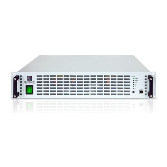
EL 9000 B 2Q Serie 1.8.4 Ansichten Bild 1 - Vorderansicht Bild 2 - Rückansicht EA Elektro-Automatik GmbH Telefon: 02162 / 3785-0 www.elektroautomatik.de Seite 13 Helmholtzstr. 31-37 • 41747 Viersen Telefax: 02162 / 16230 ea1974@elektroautomatik.de... - Page 14 EL 9000 B 2Q Serie EA Elektro-Automatik GmbH Telefon: 02162 / 3785-0 www.elektroautomatik.de Seite 14 Helmholtzstr. 31-37 • 41747 Viersen Telefax: 02162 / 16230 ea1974@elektroautomatik.de...
- Page 15 EL 9000 B 2Q Serie Bild 5 - Ansicht von oben EA Elektro-Automatik GmbH Telefon: 02162 / 3785-0 www.elektroautomatik.de Seite 15 Helmholtzstr. 31-37 • 41747 Viersen Telefax: 02162 / 16230 ea1974@elektroautomatik.de...
-
Page 16: Bedienelemente
Dient zum schnellen und einfacheren Zugriff auf die Einstellwerte des DC-Eingangs bei allen Betriebarten, au- ßer Master-Slave. Der frontseitige Port hat einen reduzierten Funktionsumfang gegenüber dem rückseitigen. Statusanzeigen (LEDs) Diese sechs farbigen LEDs zeigen jederzeit den Gerätestatus an. Mehr dazu in 1.9.4. EA Elektro-Automatik GmbH Telefon: 02162 / 3785-0 www.elektroautomatik.de Seite 16 Helmholtzstr. -
Page 17: Aufbau Und Funktion
Elemente (KE, DR, BE), die von Firmwareaktualisierungen betroffen sein können. Share & Sense Power block Controller (DR) ≈ Commu- nication (KE) EL 9000 B Block diagram EA Elektro-Automatik GmbH Telefon: 02162 / 3785-0 www.elektroautomatik.de Seite 17 Helmholtzstr. 31-37 • 41747 Viersen Telefax: 02162 / 16230 ea1974@elektroautomatik.de... -
Page 18: Lieferumfang
Steck- und nachrüstbare Schnittstellenmodule für RS232, CANopen, Ethernet, Profibus, ProfiNet, ModBus TCP oder CAN sind erhältlich. IF-AB Details zu den Schnittstellenmodulen und der Programmierung des Gerätes über diese Schnittstellen sind in weiteren Handbüchern zu finden, die auf einem dem Gerät beiliegenden USB-Stick bzw. als PDF-Download auf der Elektro-Automatik- Webseite zu finden sind. EA Elektro-Automatik GmbH Telefon: 02162 / 3785-0 www.elektroautomatik.de Seite 18 Helmholtzstr. -
Page 19: Die Bedieneinheit (Hmi)
ModBus-Protokoll oder per SCPI-Sprache angesprochen werden. Es erkennt das in einer Nachricht verwendete Protokoll automatisch. Details zur Fernsteuerung sind in weiterer Dokumentation auf der Webseite von Elektro-Automatik bzw. auf dem mitgelieferten USB-Stick zu finden. Die USB-Schnittstelle hat, wenn Fernsteuerung aktiviert werden soll, keinen Vor- rang vor dem Schnittstellenmodul (siehe unten) oder der Analogschnittstelle und kann daher nur abwechselnd zu diesem benutzt werden. -
Page 20: Steckplatz Für Schnittstellenmodule
• EL 9000 B / EL 9000 B HP / EL 9000 B 2Q • PSE 9000 • PS 9000 1U / 2U / 3U * * Ab Hardware-Revision 2, siehe Typenschild dieser Serien (falls dort keine Angabe der Revision zu finden ist, dann ist es 1) EA Elektro-Automatik GmbH Telefon: 02162 / 3785-0 www.elektroautomatik.de Seite 20 Helmholtzstr. 31-37 • 41747 Viersen Telefax: 02162 / 16230 ea1974@elektroautomatik.de... -
Page 21: Sense-Anschluß (Fernfühlung)
System verbinden kann. Die Verbindung erfolgt mit handelsüblichen CAT5-Kabeln. Durch den verwendeten Standard RS485 sind theoretisch Kabellängen bis 1200 m verwendbar. Es wird jedoch empfohlen, immer möglichst kurze Kabel zu verwenden. Für Weiteres siehe „3.7.3. Par- allelschaltung als Master-Slave (MS)“. EA Elektro-Automatik GmbH Telefon: 02162 / 3785-0 www.elektroautomatik.de Seite 21 Helmholtzstr. -
Page 22: Installation & Inbetriebnahme
Es wird empfohlen, die komplette Transportverpackung (Lieferverpackung) für die Lebensdauer des Gerätes aufzubewahren, um sie für den späteren Transport des Gerätes an einen anderen Standort oder Einsendung des Gerätes an Elektro-Automatik zwecks Reparatur wiederverwenden zu können. Im anderen Fall ist die Verpackung umweltgerecht zu entsorgen. -
Page 23: Vorbereitung
Die Haltestreifen links und rechts herausnehmen. Die mitgelieferten Leisten ( ) so einsetzen, daß die Bohrungen mit den in der Frontplatte befindlichen übereinstimmen. Die Griffe wieder anschrauben. EA Elektro-Automatik GmbH Telefon: 02162 / 3785-0 www.elektroautomatik.de Seite 23 Helmholtzstr. 31-37 • 41747 Viersen Telefax: 02162 / 16230 ea1974@elektroautomatik.de... -
Page 24: Anschließen Von Dc-Quellen
Gesamttiefe des Gerätes geplant werden soll, besonders beim Einbau in 19“-Schränke und ähnlichen. Wird die Abdeckung der DC-Klemme montiert, ist nur das hori- zontale Zuführen der DC-Leitungen möglich. EA Elektro-Automatik GmbH Telefon: 02162 / 3785-0 www.elektroautomatik.de Seite 24 Helmholtzstr. -
Page 25: Erdung Des Dc-Eingangs
• (+) Sense darf nur am (+) der Quelle und (–) Sense nur am (–) der Quelle angeschlossen werden. Ansonsten könnte die elektronische Last beschädigt werden. Siehe auch Bild 7. • Bei Master-Slave-Betrieb sollte die Fernfühlung nur am Master-Gerät erfolgen Bild 7 - Prinzip der Fernfühlungsverdrahtung EA Elektro-Automatik GmbH Telefon: 02162 / 3785-0 www.elektroautomatik.de Seite 25 Helmholtzstr. -
Page 26: Anschließen Der Usb-Ports
Schrauben der Frontplatte Platine einrasten müssen, damit das Modul des Moduls kann es ange- auf der Rückwand des Gerätes richtig aufliegt. packt werden, um es her- auszuziehen. EA Elektro-Automatik GmbH Telefon: 02162 / 3785-0 www.elektroautomatik.de Seite 26 Helmholtzstr. 31-37 • 41747 Viersen Telefax: 02162 / 16230... -
Page 27: Anschließen Der Analogen Schnittstelle
Erstinbetriebnahme. Siehe daher auch „2.3.11. Erstinbetriebnahme“. Erst nach erfolgreicher Überprüfung des Gerätes nach den gelisteten Punkten darf es wie gewohnt in Betrieb genommen werden. EA Elektro-Automatik GmbH Telefon: 02162 / 3785-0 www.elektroautomatik.de Seite 27 Helmholtzstr. -
Page 28: Bedienung Und Verwendung
Der Verlauf ist linear, der maximal aufnehmbare Strom bei einer Eingangsspannung unterhalb U kann daher einfach berechnet werden. I(A) Rechts ist eine Prinzipdarstellung zu sehen. EA Elektro-Automatik GmbH Telefon: 02162 / 3785-0 www.elektroautomatik.de Seite 28 Helmholtzstr. 31-37 • 41747 Viersen Telefax: 02162 / 16230... -
Page 29: Stromregelung / Konstantstrom / Strombegrenzung
über 30°C und wenn man z. B. bei einem Modell mit 2400 W Leistung mit konstant 1600 W arbeiten würde, bei 2400 W gesetzt, und würde einen Stromsprung oder Spannungssprung nach oben machen, könnte das Gerät trotzdem keine Ist-Leistung von 2400 W erreichen. EA Elektro-Automatik GmbH Telefon: 02162 / 3785-0 www.elektroautomatik.de Seite 29 Helmholtzstr. -
Page 30: Regelverhalten Und Stabilitätskriterium
In der Praxis wird hierfür ein Kondensator direkt am DC-Eingang an der elektronischen Last angebracht. Welcher Wert den gewünschten Effekt bringt, ist nicht festlegbar. Wir empfehlen: 80 V-Modelle: 1000 μF..4700 μF 200 V-Modelle: 100 μF...470 μF 360 V-Modelle: 68 μF...220 μF 500 V-Modelle: 47 μF...150 μF 750 V-Modelle: 22 μF...100 μF EA Elektro-Automatik GmbH Telefon: 02162 / 3785-0 www.elektroautomatik.de Seite 30 Helmholtzstr. 31-37 • 41747 Viersen Telefax: 02162 / 16230 ea1974@elektroautomatik.de... -
Page 31: Alarmzustände
• das Produkt aus der am DC-Eingang anliegenden Eingangsspannung und dem Eingangsstrom die eingestellte OPP-Schwelle überschreitet Diese Schutzfunktion dient nicht dem Schutz des Gerätes, sondern dem Schutz der speisenden Spannungs- bzw. Stromquelle, falls diese durch zu hohe Belastung beschädigt werden könnte. EA Elektro-Automatik GmbH Telefon: 02162 / 3785-0 www.elektroautomatik.de Seite 31 Helmholtzstr. -
Page 32: Manuelle Bedienung
Anzeige verfügbar ist. Dann können über den vorderen USB-Port die wichtigsten Parameter per schnellem Zugriff über eine Software eingestellt werden. Für die Konfiguration von Parametern siehe Abschnitt 3.5 bzw. die mitgelieferte Programmieranleitung. Über die mitgelieferte Software EA Power Control können auch einige Parameter konfiguriert werden. EA Elektro-Automatik GmbH Telefon: 02162 / 3785-0 www.elektroautomatik.de Seite 32 Helmholtzstr. -
Page 33: Fernsteuerung
Wegen übertragen werden. Siehe dazu die auf USB-Stick mitgelieferte Programmieranleitung. 3.5.2.3 Programmierung Details zur Programmierung der Schnittstellen, die Kommunikationsprotokolle usw. sind in der externen Doku- mentation „Programmieranleitung ModBus & SCPI“ zu finden, die mit dem Gerät auf einem USB-Stick mitgeliefert wird bzw. als Download auf der Elektro-Automatik Webseite verfügbar ist. EA Elektro-Automatik GmbH Telefon: 02162 / 3785-0 www.elektroautomatik.de Seite 33 Helmholtzstr. -
Page 34: Fernsteuerung Über Den Vorderen Usb-Port
[SOURce:]VOLTage:LIMit:LOW? SYSTem:CONFig:UCD:ACTion [SOURce:]VOLTage:PROTection[:LEVel] SYSTem:CONFig:UCD:ACTion? [SOURce:]VOLTage:PROTection[:LEVel]? SYSTem:CONFig:USER:TEXT MEASure:[SCALar:]CURRent[:DC]? SYSTem:CONFig:USER:TEXT? MEASure:[SCALar:]POWer[:DC]? SYSTem:CONFig:UVD MEASure:[SCALar:]VOLTage[:DC]? SYSTem:CONFig:UVD? INPut[:STATe] SYSTem:CONFig:UVD:ACTion INPut[:STATe]? SYSTem:CONFig:UVD:ACTion? STATus:OPERation? SYSTem:DEVice:CLAss? STATus:QUEStionable? SYSTem:ERRor:ALL? EA Elektro-Automatik GmbH Telefon: 02162 / 3785-0 www.elektroautomatik.de Seite 34 Helmholtzstr. 31-37 • 41747 Viersen Telefax: 02162 / 16230 ea1974@elektroautomatik.de... -
Page 35: Fernsteuerung Über Analogschnittstelle (As)
Wert oder auf 100% gelegt werden (Brücke nach VREF oder anders) Die Analogschnittstelle ist zum DC-Eingang hin galvanisch getrennt. Daher: Niemals eine der Massen der Analogschnittstelle mit DC- oder DC+ Eingang verbinden, wenn nicht unbedingt nötig! EA Elektro-Automatik GmbH Telefon: 02162 / 3785-0 www.elektroautomatik.de Seite 35 Helmholtzstr. - Page 36 * AI = Analoger Eingang, AO = Analoger Ausgang, DI = Digitaler Eingang, DO = Digitaler Ausgang, POT = Potential ** Interne Vcc ca. 10 V *** Nur während Fernsteuerung **** Der Fehler eines Sollwerteinganges addiert sich zum allgemeinen Fehler des zugehörigen Wertes am DC-Eingang des Gerätes EA Elektro-Automatik GmbH Telefon: 02162 / 3785-0 www.elektroautomatik.de Seite 36 Helmholtzstr.
- Page 37 Wird der Pin nicht beschaltet bzw. der angeschlossene Kontakt ist offen, ist der Pin HIGH. Bei Einstellung „Analogschnittstelle REM-SB = normal“ entspricht das der Vorgabe „DC-Eingang einschalten“. Das heißt, sobald mit Pin „REMOTE“ auf Fernsteuerung umgeschaltet wird, schaltet der DC-Eingang ein! EA Elektro-Automatik GmbH Telefon: 02162 / 3785-0 www.elektroautomatik.de Seite 37 Helmholtzstr.
- Page 38 Schrittweite für Sollwerte/Istwerte. c) Istwerte erfassen Über die AS werden die DC-Eingangswerte von Strom und Spannung mittels 0...10 V oder 0...5 V abgebildet. Zur Erfassung dienen handelsübliche Multimeter o.ä. EA Elektro-Automatik GmbH Telefon: 02162 / 3785-0 www.elektroautomatik.de Seite 38 Helmholtzstr. 31-37 • 41747 Viersen Telefax: 02162 / 16230 ea1974@elektroautomatik.de...
-
Page 39: Alarme Und Überwachung
OverPower Eingangsleistung am DC-Eingang die eingestellte 0 W...1,1*P digitale Schnitt- Nenn Protection Schwelle erreicht. Außerdem wird der DC-Eingang stellen ausgeschaltet. EA Elektro-Automatik GmbH Telefon: 02162 / 3785-0 www.elektroautomatik.de Seite 39 Helmholtzstr. 31-37 • 41747 Viersen Telefax: 02162 / 16230 ea1974@elektroautomatik.de... - Page 40 0 W...P Nenn Schwelle überschreitet. Sobald ein Event durch Setzen der Aktion auf eine Einstellung anders als KEINE konfiguriert wurde, könnte es ausgelöst werden, wenn der DC-Eingang momentan eingeschaltet ist. Es wird daher empfohlen, Events nur bei ausgeschaltetem DC-Eingang zu konfigurieren. EA Elektro-Automatik GmbH Telefon: 02162 / 3785-0 www.elektroautomatik.de Seite 40 Helmholtzstr. 31-37 • 41747 Viersen Telefax: 02162 / 16230...
-
Page 41: Anwendungen
Typische Anwendungen: • Brennstoffzellen • Kondensatortests • motorisch betriebene Anwendungen • Elektroniktests, wo eine höhere Dynamik für Entladevorgänge erforderlich ist EA Elektro-Automatik GmbH Telefon: 02162 / 3785-0 www.elektroautomatik.de Seite 41 Helmholtzstr. 31-37 • 41747 Viersen Telefax: 02162 / 16230 ea1974@elektroautomatik.de... - Page 42 Master auf dem digitalen MS-Bus ist. Zur Sicherheit der Gesamtanwendung und hauptsächlich des Prüflings wird empfohlen, die Überwachungsgren- zen wie OVD/OVP bei Netzgeräten bzw. UVD bei Lasten auf passende Werte zu setzen, damit im Fehlerfall der DC-Ausgang der Quelle bzw. DC-Eingang der Senke abgeschaltet wird und der Prüfling keinen Schaden nimmt. EA Elektro-Automatik GmbH Telefon: 02162 / 3785-0 www.elektroautomatik.de Seite 42 Helmholtzstr. 31-37 • 41747 Viersen Telefax: 02162 / 16230 ea1974@elektroautomatik.de...
- Page 43 Batteriespannung verringert, als Reaktion auf den sich ändernden Innenwiderstand der Batterie. Die Last nimmt während der Aufladephase keinen Strom auf, weil sie über die Share-Bus-Verbindung einen Sollwert übermittelt bekommt der höher liegt als die momentane Batteriespannung. Bei Erreichen von 27 V wird das Netz- gerät nur noch den Erhaltungsladestrom für die Batterie liefern. EA Elektro-Automatik GmbH Telefon: 02162 / 3785-0 www.elektroautomatik.de Seite 43 Helmholtzstr.
-
Page 44: Reihenschaltung
B. EL 9080-170 B 2Q mit EL 9080-170 B 2Q oder mit EL 9080-170 B HP • Geräte an den Enden des Busses sollten terminiert werden (siehe unten) Der Master-Slave-Bus darf nicht über Crossover-Kabel verbunden werden! EA Elektro-Automatik GmbH Telefon: 02162 / 3785-0 www.elektroautomatik.de Seite 44 Helmholtzstr. - Page 45 Sie den Master-Slave-Modus und legen gleichzeitig das Gerät als Master-Gerät fest. Die Warnmeldung bestätigen Sie mit OK, ansonsten wird die Änderung nicht übernommen. Übernehmen Sie die Einstellungen mit Bedienfeld und verlassen Sie das Einstellmenü. EA Elektro-Automatik GmbH Telefon: 02162 / 3785-0 www.elektroautomatik.de Seite 45 Helmholtzstr.
- Page 46 • Alle Geräte, auch die Slaves, können über den Pin „Rem-SB“ der analogen Schnittstelle DC-seitig ausgeschaltet werden. Das ist eine Art Notfallabschaltung (kein Not-Aus!), die üblicherweise über einen Kontakt gesteuert zu allen beteiligten Geräten parallel verdrahtet wird. EA Elektro-Automatik GmbH Telefon: 02162 / 3785-0 www.elektroautomatik.de Seite 46 Helmholtzstr.
- Page 47 System arbeiten soll erforderlich sein, bei den inaktiven Einheiten den Share-Bus-Stecker ab- zuziehen, weil sie auch im ausgeschaltetem Zustand durch ihre Impedanz auf den Share-Bus wirken und störend beeinflussen könnten. EA Elektro-Automatik GmbH Telefon: 02162 / 3785-0 www.elektroautomatik.de Seite 47 Helmholtzstr.
-
Page 48: Instandhaltung & Wartung
Verdachtsfall den Lieferanten und klären Sie mit ihm weitere Schritte ab. Üblicherweise wird es dann nötig werden, das Gerät an Elektro-Automatik zwecks Reparatur (mit Garantie oder ohne) einzuschicken. Im Fall, daß eine Einsendung zur Überprüfung bzw. Reparatur ansteht, stellen Sie sicher, daß... -
Page 49: Service & Support
Service & Support Reparaturen Reparaturen, falls nicht anders zwischen Anwender und Lieferant ausgemacht, werden durch Elektro-Automatik durchgeführt. Dazu muß das Gerät im Allgemeinen an den Hersteller eingeschickt werden. Es wird keine RMA- Nummer benötigt. Es genügt, das Gerät ausreichend zu verpacken, eine ausführliche Fehlerbeschreibung und, bei noch bestehender Garantie, die Kopie des Kaufbelegs beizulegen und an die unten genannte Adresse einzuschicken. - Page 52 EA-Elektro-Automatik GmbH & Co. KG Entwicklung - Produktion - Vertrieb Helmholtzstraße 31-37 41747 Viersen Telefon: 02162 / 37 85-0 Telefax: 02162 / 16 230 ea1974@elektroautomatik.de www.elektroautomatik.de...
- Page 53 Operating Manual EL 9000 B 2Q Electronic DC Load Doc ID: EL9QEN Revision: 01 Date: 05/2017...
- Page 55 EL 9000 B 2Q Series TABLE OF CONTENTS GENERAL About this document ........4 2.3.11 Initial commission .........27 1.1.1 Retention and use ..........4 2.3.12 Commission after a firmware update or a long period of non-use .........27 1.1.2 Copyright ............4 1.1.3 Validity ............4 1.1.4 Symbols and warnings ........4 OPERATION AND APPLICATION Warranty ............4...
-
Page 56: About This Document
Limit of liability All statements and instructions in this manual are based on current norms and regulations, up-to-date technology and our long term knowledge and experience. EA Elektro-Automatik accepts no liability for losses due to: • Usage for purposes other than defined • Use by untrained personnel • Rebuilding by the customer... -
Page 57: Disposal Of Equipment
A piece of equipment which is intended for disposal must, according to European laws and regulations (ElektroG, WEEE) be returned to EA Elektro-Automatik for scrapping, unless the person operating the piece of equipment or another, delegated person is conducting the disposal. Our equipment falls under these regulations and is accord-... -
Page 58: Safety
EL 9000 B 2Q Series Safety 1.7.1 Safety notices Mortal danger - Hazardous voltage • Electrical equipment operation means that some parts will be under dangerous voltage. Therefore all parts under voltage must be covered! • All work on connections must be carried out under zero voltage (input not connected to voltage sources) and may only be performed by qualified and informed persons. -
Page 59: Responsibility Of The Operator
EL 9000 B 2Q Series 1.7.3 Responsibility of the operator Operator is any natural or legal person who uses the equipment or delegates the usage to a third party, and is responsible during its usage for the safety of the user, other personnel or third parties. -
Page 60: Alarm Signals
EL 9000 B 2Q Series 1.7.5 Alarm signals Alarm conditions, not danger situations, are signalled on the front of this device in form of a red LED “Error” (also see section 1.8.4.). The LED collects all of the below listed alarm situations. If there is supervision of the slave units being used, alarms can be decoded by querying a status from the device via any of the digital interfaces. -
Page 61: Specific Technical Data
EL 9000 B 2Q Series 1.8.3 Specific technical data Model 2Q Up to 1200 W EL 9080-85 B EL 9200-35 B EL 9360-20 B EL 9500-15 B EL 9750-10 B AC mains supply Supply voltage 90...264 V AC 90...264 V AC 90...264 V AC... - Page 62 EL 9000 B 2Q Series Model 2Q Up to 1200 W EL 9080-85 B EL 9200-35 B EL 9360-20 B EL 9500-15 B EL 9750-10 B Insulation DC minus: permanent max. ±400 V Input (DC) to enclosure DC plus: permanent max. ±400 V + max. input voltage Input (AC) to input (DC) Max.
- Page 63 EL 9000 B 2Q Series Model 2Q Up to 2400 W EL 9080-170 B EL 9200-70 B EL 9360-40 B EL 9500-30 B EL 9750-20 B AC mains supply Supply voltage 90...264 V AC 90...264 V AC 90...264 V AC 90...264 V AC...
- Page 64 EL 9000 B 2Q Series Model 2Q Up to 2400 W EL 9080-170 B EL 9200-70 B EL 9360-40 B EL 9500-30 B EL 9750-20 B Insulation DC minus: permanent max. ±400 V Input (DC) to enclosure DC plus: permanent max. ±400 V + max. input voltage Input (AC) to input (DC) Max.
-
Page 65: Views
EL 9000 B 2Q Series 1.8.4 Views Figure 1 - Front view Figure 2 - Rear view EA Elektro-Automatik GmbH Fon: +49 2162 / 3785-0 www.elektroautomatik.de Page 13 Helmholtzstr. 31-37 • 41747 Viersen Fax: +49 2162 / 16230 ea1974@elektroautomatik.de Germany... - Page 66 EL 9000 B 2Q Series EA Elektro-Automatik GmbH Fon: +49 2162 / 3785-0 www.elektroautomatik.de Page 14 Helmholtzstr. 31-37 • 41747 Viersen Fax: +49 2162 / 16230 ea1974@elektroautomatik.de Germany...
- Page 67 EL 9000 B 2Q Series Figure 5 - Top view EA Elektro-Automatik GmbH Fon: +49 2162 / 3785-0 www.elektroautomatik.de Page 15 Helmholtzstr. 31-37 • 41747 Viersen Fax: +49 2162 / 16230 ea1974@elektroautomatik.de Germany...
-
Page 68: Control Elements
EL 9000 B 2Q Series 1.8.5 Control elements Figure 6 - Control Panel Overview of the elements of the operating panel For a detailed description see section „1.9.5. The control panel (HMI)“. On/Off button Can be used to switch the DC input on or off during manual operation, while LED “Remote” = off... -
Page 69: Construction And Function
EL 9000 B 2Q Series Construction and function 1.9.1 General description The 2Q in the series name EL 9000 B 2Q stands for “two-quadrants”and points the main purpose of these device which is to run as electronic load in a so-called two-quadrants system which is controlled by a power supply unit. -
Page 70: Scope Of Delivery
EL 9000 B 2Q Series 1.9.3 Scope of delivery 1 x Electronic load device 1 x Share Bus plug 1 x Remote sensing plug 2 x Fill strip (for the purpose see 2.3.3.1) 1 x 1.8 m USB cable 1 x Set of DC terminal cover(s) -
Page 71: The Control Panel (Hmi)
EL 9000 B 2Q Series 1.9.5 The control panel (HMI) The HMI (Human Machine Interface) consists of six coloured LEDs, a pushbutton and an USB-B port. 1.9.5.1 Status indicators (LED) The six coloured LEDs on the front indicate various statuses of the device:... -
Page 72: Interface Module Slot
EL 9000 B 2Q Series 1.9.7 Interface module slot This slot on the back side of the device is used to install one of various modules of the IF-AB interface series. The following options are available: Ordering no. Name Description... -
Page 73: Sense" Connector (Remote Sensing)
EL 9000 B 2Q Series 1.9.10 “Sense” connector (remote sensing) In order to compensate for voltage drops along the DC cables from the source, the Sense input can be connected to the source. The maximum possible compensation is given in the technical data. For more refer to „2.3.7. Connection of remote sensing“. -
Page 74: Installation & Commissioning
2.1.2 Packaging It is recommended to keep the complete transport packaging for the lifetime of the device for relocation or return to Elektro-Automatik for repair. Otherwise the packaging should be disposed of in an environmentally friendly way. 2.1.3 Storage In case of long term storage of the equipment it is recommended to use the original packaging or similar. Storage must be in dry rooms, if possible in sealed packaging, to avoid corrosion, especially internal, through humidity. -
Page 75: Preparation
EL 9000 B 2Q Series 2.3.2 Preparation Connection to mains of electronic loads of EL 9000 B 2Q only requires a standard wall socket. The mains cord is included in the scope of delivery. The devices only consume little power, so there are no further installation or safety measures required. -
Page 76: Connection To Dc Sources
EL 9000 B 2Q Series 2.3.4 Connection to DC sources In the case of a device with a high nominal current and hence a thick and heavy DC connec- tion cable it is necessary to take account of the weight of the cable and the strain imposed on the DC connection. -
Page 77: Grounding Of The Dc Input
EL 9000 B 2Q Series 2.3.5 Grounding of the DC input The device can always be grounded on the DC minus pole, i.e. can be directly connected to PE. The DC plus pole, however, if it is to be grounded, may only be so for input voltages up to 400 V, because the potential of the minus pole is shifted into negative direction by the value of the input voltage. Also see technical specification sheets in... -
Page 78: Connecting The Usb Ports
EL 9000 B 2Q Series 2.3.8 Connecting the USB ports In order to remotely control the device via this port, connect the device with a PC using the included USB cable and switch the device on. 2.3.8.1 Driver installation (Windows) On the initial connection with a PC the operating system will identify the device as new hardware and will try to install a driver. -
Page 79: Connecting The Analog Interface
EL 9000 B 2Q Series 2.3.10 Connecting the analog interface The 15 pole connector (Type: Sub-D, D-Sub) on the rear side is an analog interface. To connect this to a control- ling hardware (PC, electronic circuit), a standard plug is necessary (not included in the scope of delivery). It is generally advisable to switch the device completely off before connecting or disconnecting this connector, but at least the DC input. -
Page 80: Operation And Application
EL 9000 B 2Q Series Operation and application Personal safety • In order to guarantee safety when using the device, it is essential that only persons operate the device who are fully acquainted and trained in the required safety measures to be taken when working with dangerous electrical voltages • For models which accept dangerous voltages, the included DC terminal cover, or an equivalent,... -
Page 81: Current Regulation / Constant Current / Current Limitation
EL 9000 B 2Q Series 3.2.2 Current regulation / constant current / current limitation Current regulation is also known as current limitation or constant current mode (CC) and is fundamental to the normal operation of an electronic load. The DC input current is held at a predetermined level by varying the internal resistance according to Ohm’s law R = U / I such that, based on the input voltage, a constant current flows. Once... -
Page 82: Dynamic Characteristics And Stability Criteria
EL 9000 B 2Q Series Principle view of the derating characteristics: Starting at around 30°C (86°F) ambient tempera- ture, the derating will continuously step down the available input power. The temperature range of the device is rated up to 50°C (122°F). Above that point, the system could shut down because of overtemperature (OT). -
Page 83: Alarm Conditions
EL 9000 B 2Q Series Alarm conditions This section only gives an overview about device alarms. What to do in case your device in- dicates an alarm condition is described in section „3.6 Alarms and monitoring“ on page 39. As a basic principle, all alarm conditions are signalled optically (by LED “Error” on the front) and via the digital interface ports. -
Page 84: Manual Operation
EL 9000 B 2Q Series Manual operation 3.4.1 Powering the device The device should, as far as possible, always be switched on using the toggle switch on the front of the device. Alternatively this can take place using an external cutout (contactor, circuit breaker) of suitable current capacity. -
Page 85: Remote Control
EL 9000 B 2Q Series Remote control 3.5.1 General Remote control is possible via the built-in analog or any of the digital interfaces. Digital interfaces are the two USB ports, the optional interface modules and also the closed master-slave bus, via which the device could be controlled by a master unit in master-slave operation. -
Page 86: Remote Control Via The Front Usb
EL 9000 B 2Q Series 3.5.3 Remote control via the front USB The main purpose of the front USB port is quick access to the most important DC input related parameters, such as set values and protections. Reading values and status is always possible, setting them only while the device is not in control by a master device while running in master-slave operation. -
Page 87: Remote Control Via The Analog Interface (Ai)
EL 9000 B 2Q Series SYSTem:ERRor:NEXT? SYSTem:NOMinal:CURRent? SYSTem:ERRor? SYSTem:NOMinal:POWer? SYSTem:LOCK SYSTem:NOMinal:RESistance:MAXimum? SYSTem:LOCK? SYSTem:NOMinal:RESistance:MINimum? SYSTem:LOCK:OWNer? SYSTem:NOMinal:VOLTage? 3.5.4 Remote control via the analog interface (AI) 3.5.4.1 General The built-in, galvanically isolated, 15-pole analog interface (short: AI) is on the back side of the device offers the following possibilities: • Remote control of current, voltage, power and resistance... - Page 88 EL 9000 B 2Q Series 3.5.4.2 Acknowledging device alarms Device alarms (see 3.6.2) are always indicated via LED “Error” on the front and some of them are also reported as signal on the analog interface socket (see table below). In case of a device alarm occurring during remote control via analog interface, the DC input will be switched off the same way as in other control modes.
- Page 89 EL 9000 B 2Q Series 3.5.4.5 Overview of the Sub-D Socket 3.5.4.6 Simplified diagram of the pins Digital Input (DI) Analog Input (AI) It requires to use a switch with low resist- High resistance input (impedance V~0.5 ance (relay, switch, circuit breaker etc.) in >40 k..100 kΩ) for an OA circuit.
- Page 90 EL 9000 B 2Q Series • Remote control is not active In this mode of operation pin “REM-SB” can serve as lock, preventing the DC input from being switched on by any means. This results in following possible situations: Parameter ...
-
Page 91: Alarms And Monitoring
EL 9000 B 2Q Series Alarms and monitoring 3.6.1 Definition of terms The device signalises alarms (see „3.3. Alarm conditions“) via the front LED “Error” and as readable status via digital interface. When running the device as Slave as part of a master-slave system, the alarm is also reported to the master and if the master is a model with display (different series), the alarm is indicated there as well. - Page 92 EL 9000 B 2Q Series These device alarms can’t be configured and are based on hardware: Alarm Meaning Description Indication AC supply over- or undervoltage. Triggers an alarm if the AC supply is out LED “Error”, Power Fail of specification or when the device is cut from supply, for example when analog & digital switching it off with the power switch. The DC input will be switched off.
-
Page 93: Other Applications
EL 9000 B 2Q Series Other applications 3.7.1 Two quadrants operation (2QO) 3.7.1.1 Introduction This kind of operation refers to the use of a source, in this case a power supply from a compatible series (see section „1.9.9. “Share” connector“) and a sink, in this case a series EL 9000 B 2Q electronic load. - Page 94 EL 9000 B 2Q Series Configuration B: E-LOAD n PSU n Multiple e-loads and multiple power supplies for increased total performance, plus 1 test object (E.U.T). The combination of load units and power supply units each create a block, a system with a certain power. Here it is also...
- Page 95 EL 9000 B 2Q Series The power supply determines the voltage setting of the load via the Share bus. In order to avoid deep discharge of the battery due to accidentally setting the voltage on the power supply to a very low value, it is recommended to configure the undervoltage detection feature (UVD) of the load, so it will switch off the DC input when reaching minimum allowed discharge voltage.
-
Page 96: Series Connection
EL 9000 B 2Q Series 3.7.2 Series connection Series connection is not a permissible operating method for electronic loads and must not be installed or operated under any circumstances! 3.7.3 Parallel operation in master-slave (MS) Apart from the primary function of this series, to work in a two-quadrants operation driven by a power supply, the loads can also be used as slave devices as part of a master-slave system of multiple loads. - Page 97 EL 9000 B 2Q Series ► How to connect the master-slave bus Switch off all units that are to be connected and connect them together with a network cable (CAT3 or better, not included). It doesn’t matter which of the two master-slave connection sockets is connected to the next unit.
- Page 98 EL 9000 B 2Q Series 3.7.3.5 Operating the master-slave system 2Q models don’t indicate their status as “Slave” or “Master” separately. Only when being “Slave”, the LED “Remote” on the front is lit. As slave they can no longer be controlled manually or remotely, neither via the analog nor via digital interfaces.
-
Page 99: Service And Maintenance
Contact the supplier in case of suspicion and elicit the steps to be taken. It will then usually be necessary to return the device to Elektro-Automatik (with or without warranty). If a return for checking or repair is to be carried out, ensure that: • the supplier has been contacted and it is clarified how and where the equipment should be sent. -
Page 100: Contact And Support
Contact and support Repairs Repairs, if not otherwise arranged between supplier and customer, will be carried out by EA Elektro-Automatik. For this the equipment must generally be returned to the manufacturer. No RMA number is needed. It is sufficient to package the equipment adequately and send it, together with a detailed description of the fault and, if still under guarantee, a copy of the invoice, to the following address. - Page 102 EA-Elektro-Automatik GmbH & Co. KG Development - Production - Sales Helmholtzstraße 31-37 41747 Viersen Germany Fon: 02162 / 37 85-0 ea1974@elektroautomatik.de www.elektroautomatik.de Distributed by: dataTec ▪ Ferdinand-Lassalle-Str. 52 ▪ 72770 Reutlingen ▪ Tel. 07121 / 51 50 50 ▪ Fax 07121 / 51 50 10 ▪ info@datatec.de ▪ www.datatec.de...
Need help?
Do you have a question about the EL 9000 B 2Q Series and is the answer not in the manual?
Questions and answers