Sign In
Upload
Manuals
Brands
Edgetech Manuals
Sonar
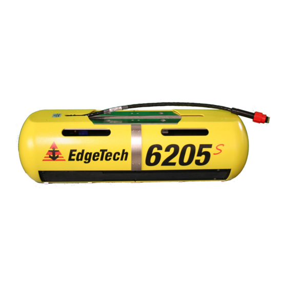
6205S
User Manuals: Edgetech 6205S Bathymetry Scan Sonar
Manuals and User Guides for Edgetech 6205S Bathymetry Scan Sonar. We have
2
Edgetech 6205S Bathymetry Scan Sonar manuals available for free PDF download: User Hardware Manual
Edgetech 6205S User Hardware Manual (97 pages)
BATHYMETRY & SIDE SCAN SYSTEM
Brand:
Edgetech
| Category:
Sonar
| Size: 6 MB
Table of Contents
Attention - Read this First
3
Hardware Variations and Compatibility
4
About this Document
5
Liability
5
Revision History
5
Warranty Statement
6
Software Service Overview
7
Software Updates and Enhancements
7
Returned Material Authorization
8
RMA Purpose
8
Customer Service
9
Company Background
10
Table of Contents
11
Table of Contents
14
List of Figures
14
List of Tables
18
Overview
18
Applications
19
Options
19
Main System Components
19
Discover Software
20
Third-Party Software
20
Optional Equipment
20
Adaptor Flange
20
Figure 1-1: the 6205S and the Optional Adaptor Flange
20
System Description
21
The 6205S Sonar Head
21
Figure 2-1: 6205S Sonar Head Components
22
Figure 2-2: the Mounting Plate
23
Figure 2-3: the Optional Adaptor Flange Installed Onto the Mounting Plate
23
Mounting Plate
23
Housing
24
Sonar Processor
24
Sound Velocity Sensor
24
Figure 2-4: 6205S Electronics Housing and Arrays Installed
25
Acoustic Center
26
Sonar Arrays
26
Figure 2-5: Acoustic Center Location in X, Y, and Z and Bolt Pattern of Standard 6205S - 0019604
27
Figure 2-6: Acoustic Center Location in X, Y, and Z Dimensions and Bolt Pattern with Adaptor Flange - 0021206
28
Specifications
29
Physical Specifications
29
Acoustic Specifications
29
Power Requirements
31
Environmental Specifications
31
Topside Specifications
31
The 6205S Topside Sonar Interface Box
32
6205S-R Rack Mount Topside Interface
33
6205S-P Portable Topside Interface
33
Figure 3-1: Rack Mount Topside
33
Topside Computer Requirements Specifications
34
Figure 3-2: 6205S-P Portable Topside
34
Figure 3-3: 6205S-P Portable Topside Interface Box, Side View
34
Deck Cable
35
Mechanical Drawings
36
Figure 3-4: 6205S Exploded View
36
Figure 3-5: 6205S Exploded View with Adaptor Flange
37
Figure 3-6: 6205S Transducer
38
Figure 3-7: 6205S Array Color Codes Diagram
39
Figure 3-8: 6205S Wiring Diagram - 0019627
40
Connections and Formats
41
Data Formats
41
System Connections and Data Flow
42
Ethernet LAN Connections
42
Serial Port Connections
43
Hardware Connectivity
43
Figure 4-1: 6205S Rack Mount Topside Interface Connections
43
Serial Port Configuration Examples
44
Ethernet Port Configuration Examples
45
Figure 4-2: 6205S-R Rack Mount Topside Interface Connections
45
PPS Port Configuration
46
Sonar Data Flow
47
Figure 4-3: Figure 4 3: 6205S System Is Optimized to Work with a Falling Edge 1PPS Signal
47
Figure 4-4: Sonar Data Flowchart
48
Topside Provided Isolation
50
Figure 4-5: Chevron Pattern Noise in a Cropped Portion of Discover Bathymetric
50
Installation
51
Unpacking and Inspecting
51
Sonar Head Installation
51
Over-The-Bow Deployment
52
Figure 5-1: 6205S Deployment, Option 1 - Over-The-Bow
52
Over-The-Side Deployment
53
USV Deployment
53
Figure 5-2: 6205S Deployment, Option 2 - Over-The-Side
53
Positioning the Topside Interface Box
54
Figure 5-3: 6205S Deployment, Option 3 - to a USV (Sea Robotics in this Example)
54
Field Exchangeable Frequency Operations
55
Figure 5-4: Unit on Stable Platform
55
Figure 5-5: Removing the Cap Screws
56
Figure 5-6: Top Housing and Deck Cable Removed
56
Figure 5-7: Remove the Center Bracket
57
Figure 5-8: Remove the Portion of the Shell 'Edgetech' and the Logo
57
Figure 5-10: Remove the [6] Cap Screws
58
Figure 5-9: the Disconnected Bathymetry and Side Scan Sonar Cables
58
Figure 5-11: All Cap Screws Removed
59
Figure 5-12: Remove the Existing Transducer
59
Figure 5-13: Mount the New Transducer
60
Connect to Sonar
61
Connecting to Sonar Via Remote Desktop
61
Connecting with the 6205S-R
61
Figure 6-1: Manual Remote Desktop Credentials for Customer Supplied Computer
61
Connecting with the 6205S-P
62
Confirming Supporting Data Is Present
62
Figure 6-2: Sonar 192.9.0.101 Remote Desktop Connection Window
62
Figure 6-3: Sonar 192.9.0.101 Remote Desktop Connection Window
63
Figure 6-4: Serial Port Information Window
64
Figure 6-5: Sensor Usage Percentage Check
65
Figure 6-6: System Status Window
66
Maintenance
67
Troubleshooting
68
Troubleshooting the SV Sensor
68
Figure 8-2: Sonar 192.9.0.101 Remote Desktop Connection Window
68
Figure 8-3: Closing the Sonar.exe Application
69
Figure 8-4: Connecting to COM4 Using Teraterm
69
Figure 8-5: COM4 Port Settings
70
Configuring Auxiliary Sensors for Redundant Information
71
Two Different Sensors Supplying the same Message
71
Figure 8-6: Scrolling SV Data in Sonar.exe
71
Figure 8-7: Configuration Menu
72
Figure 8-8: Auxiliary Sensors
72
Two Sensors Output same Information with Different Messages
73
Figure 8-9: Sonar Control Tab
73
Figure 8-10: Sonarser-All.ini
74
Configuring COM Ports
75
One Sensor
75
Figure 8-11: Sonar Remote Desktop Application, Main Screen
75
Figure 8-12: Finding the Sonarserial.ini File
76
Figure 8-13: Sonarserial.ini File
76
Figure 8-14: Diagnostic Window, Reporting Ports Inactive Error
77
Figure 8-15: Rebooting Sonar from the Main Screen
78
Figure 8-16: Checking Serial Port Information
79
Figure 8-17: Checking Sensor Status
79
Figure 8-18: Closing the System Status Window
80
Two Sensors
81
Figure 8-19: Sonarserial.ini File
81
Three Sensors
83
Figure 8-20: Checking Sensors' Usages
83
Figure 8-21: All Sensors Set
84
Figure 8-22: Checking All COM Ports
86
UDP Connections
87
Figure 8-23: UDP Configuration Example
87
Applanix POSMV Configuration
88
Figure 8-24: POSMV UDP Configuration
89
Figure 8-25: Sonarconfig.ini Example
90
Figure 8-26: Timesyncsource Keyword Adjustments
90
SBG Ekinox/Apogee Configuration
91
Figure 8-27: Timesyncsource Keyword Adjustments
91
Figure 8-28: UDP Broadcast Settings Example
92
Figure 8-29: Eth1 Data Output
92
Figure 8-30: Data Packets Required, but at 25Hz or 50Hz, Not 1Hz
93
Figure 8-31: 1PPS Settings Example, Falling Edge and 1Msec Duration
94
System Restore
95
Compatible SOFTWARE
96
Discover Bathymetric
96
Third-Party Software
96
Hypack
96
Sonarwiz
96
Qinsy
97
Caris
97
EIVA Navisuite
97
BEAMWORX Suite
97
Advertisement
Edgetech 6205S User Hardware Manual (88 pages)
Bathymetry & side scan system
Brand:
Edgetech
| Category:
Sonar
| Size: 5 MB
Table of Contents
Attention - Read this First
3
Hardware Variations and Compatibility
4
About this Document
5
Liability
5
Revision History
5
Warranty Statement
6
Software Service Overview
7
Software Updates and Enhancements
7
Returned Material Authorization
8
RMA Purpose
8
Customer Service
9
Company Background
10
Table of Contents
11
Table of Contents
14
List of Figures
14
List of Tables
17
Section 1: Overview
17
Applications
18
Options
18
Main System Components
18
DISCOVER Software
19
Third-Party Software
19
Optional Equipment
19
Adaptor Flange
19
Figure 1-1: the 6205S and the Optional Adaptor Flange
19
Section 2: System Description
20
The 6205S Sonar Head
20
Figure 2-1: 6205S Sonar Head Components
21
Figure 2-2: the Mounting Plate
22
Figure 2-3: the Optional Adaptor Flange Installed Onto the Mounting Plate
22
Mounting Plate
22
Housing
23
Sonar Processor
23
Sound Velocity Sensor
23
Figure 2-4: 6205S Electronics Housing and Arrays Installed
24
Acoustic Center
25
Sonar Arrays
25
Figure 2-5: Acoustic Center Location in X, Y, and Z and Bolt Pattern of Standard 6205S - 0019604
26
Figure 2-6: Acoustic Center Location in X, Y, and Z Dimensions and Bolt Pattern with Adaptor Flange
27
Section 3: Specifications
28
Physical Specifications
28
Acoustic Specifications
28
Power Requirements
29
Environmental Specifications
30
Topside Specifications
30
The 6205S Topside Sonar Interface Box
31
6205S-R Rack Mount Topside Interface
32
Figure 3-1: Rack Mount Topside
32
6205S-P Portable Topside Interface
33
Figure 3-2: 6205S-P Portable Topside
33
Topside Computer Requirements Specifications
34
Figure 3-3: 6205S-P Portable Topside Interface Box, Side View
34
Deck Cable
35
Mechanical Drawings
35
Figure 3-4: 6205S Exploded View
36
Figure 3-5: 6205S Exploded View with Adaptor Flange
37
Figure 3-6: 6205S Transducer
38
Figure 3-7: 6205S Array Color Codes Diagram
39
Figure 3-8: 6205S Wiring Diagram - 0019627
40
Section 4: Connections and Formats
41
Data Formats
41
System Connections and Data Flow
42
Ethernet LAN Connections
42
Serial Port Connections
43
Hardware Connectivity
43
Figure 4-1: 6205S-R Rack Mount Topside Interface Connections
43
Serial Port Configuration Examples
44
Sonar Data Flow
45
Figure 4-2: Sonar Data Flow
45
Topside Provided Isolation
47
Figure 4-3: Chevron Pattern Noise in a Cropped Portion of Discover Bathymetric
47
Section 5: Installation
48
Unpacking and Inspecting
48
Sonar Head Installation
48
Over-The-Bow Deployment
49
Figure 5-1: 6205S Deployment, Option 1 - Over-The-Bow
49
Over-The-Side Deployment
50
Positioning the Topside Interface Box
50
Figure 5-2: 6205S Deployment, Option 2 - Over-The-Side
50
Topside Connections
51
Field Exchangeable Frequency Operations
52
Tools
52
Figure 5-3: Unit on Stable Platform
53
Figure 5-4: Removing the Cap Screws
53
Figure 5-5: Top Housing and Deck Cable Removed
54
Figure 5-6: Remove the Center Bracket
54
Figure 5-7: Remove the Portion of the Shell 'Edgetech' and the Logo
55
Figure 5-8: the Disconnected Bathymetry and Side Scan Sonar Cables
55
Figure 5-9: Remove the [6] Cap Screws
56
Figure 5-10: All Cap Screws Removed
56
Figure 5-11: Remove the Existing Transducer
56
Figure 5-12: Mount the New Transducer
57
Section 6: Connect to Sonar
58
Connecting to Sonar Via Remote Desktop
58
Connecting with the 6205S-R
58
Figure 6-1: Manual Remote Desktop Credentials for Customer Supplied Computer
58
Connecting with the 6205S-P
59
Figure 6-2: Sonar 192.9.0.101 Remote Desktop Connection Window
59
Confirming Supporting Data Is Present
60
Figure 6-3: Sonar 192.9.0.101 Remote Desktop Connection Window
60
Figure 6-4: Serial Port Information Window
61
Figure 6-5: System Status Window
62
Section 7: Maintenance
63
Section 8: Troubleshooting
64
Troubleshooting the SV Sensor
64
Figure 8-2: Sonar 192.9.0.101 Remote Desktop Connection Window
64
Figure 8-3: Closing the Sonar.exe Application
65
Figure 8-4: Connecting to COM4 Using Teraterm
65
Figure 8-5: COM4 Port Settings
66
Configuring Auxiliary Sensors for Redundant Information
67
Two Different Sensors Supplying the same Message
67
Figure 8-6: Scrolling SV Data in Sonar.exe
67
Figure 8-7: Configuration Menu
68
Figure 8-8: Auxiliary Sensors
68
Two Sensors Output same Information with Different Messages
69
Figure 8-9: Sonar Control Tab
69
Figure 8-10: Sonarseral.ini
70
Appendix A: Configuring Com Ports
71
One Sensor
71
Figure A-1: Sonar Remote Desktop Application, Main Screen
72
Figure A-2: Sonar Remote Desktop, Shortcut to Edgetech Folder
72
Figure A-3: Finding the Sonarserial.ini File
72
Figure A-4: Sonarserial.ini File
73
Figure A-5: Diagnostic Window, Reporting Ports Inactive Error
73
Figure A-6: Rebooting Sonar from the Main Screen
74
Figure A-7: Checking Serial Port Information
75
Figure A-8: Checking Sensor Status
75
Two Sensors
76
Figure A-9: Closing the System Status Window
76
Figure A-10: Sonarserial.ini File
77
Figure A-11: Checking Sensors' Usages
78
Three Sensors
79
Figure A-12: All Sensors Set
79
Figure A-13: Checking All COM Ports
81
UDP Connections
82
Figure A-14: UDP Configuration Example
82
POSMV Configuration
83
Figure A-15: POSMV UDP Configuration
83
Figure A-16: Sonarconfig.ini Example
84
Figure A-17: Timesyncsoruce Keyword Adjustments
84
Appendix B: Software
86
Discover Bathymetric
86
Third Party Software
86
Hypack
86
Sonarwiz
86
Qinsy
87
Caris
87
EIVA Navisuite
87
Appendix C: System Restore
88
Advertisement
Related Products
Edgetech 6205S2
EdgeTech 2000-CSS
Edgetech 2000-DSS
Edgetech 2000-TVD
Edgetech 2205
Edgetech 2300
Edgetech 2300B
EDGE Tech 4125 Series
EdgeTech 4125 SIDE SCAN
Edgetech 4125I
Edgetech Categories
Marine Equipment
Sonar
Measuring Instruments
Fishing Equipment
Scanner
More Edgetech Manuals
Login
Sign In
OR
Sign in with Facebook
Sign in with Google
Upload manual
Upload from disk
Upload from URL