Edgetech 4205 User Hardware Manual
Side scan system
Hide thumbs
Also See for 4205:
- User hardware manual (108 pages) ,
- Manual (35 pages) ,
- User hardware manual (86 pages)

Related Manuals for Edgetech 4205


Summary of Contents for Edgetech 4205
- Page 1 4205 SIDE SCAN SYSTEM U S E R H A R D W A R E M A N U A L 0021769_REV_F 6/1/2021 EdgeTech 4 Little Brook Road West Wareham, MA 02576 Tel: (508) 291-0057 Fax: (508) 291-2491 www.EdgeTech.com...
- Page 2 The information, figures, and specifications in this manual are proprietary. They are issued in strict confidence on condition that they not be copied, reprinted, or disclosed to a third party, either wholly or in part, without the prior written consent of EdgeTech. Any reproduction of EdgeTech supplied software or file sharing is strictly prohibited.
-
Page 3: Attention - Read This First
ATTENTION – READ THIS FIRST! All personnel involved with the installation, operation, or maintenance of the equipment described in this manual should read and understand the warnings and cautions provided below. CAUTION! This equipment contains devices that are extremely sensitive to static electricity. -
Page 4: Hardware Variations And Compatibility
HARDWARE VARIATIONS AND COMPATIBILITY The 4205 Side Scan System contains both standard and proprietary hardware. At times, EdgeTech may change the standard components due to their availability or performance improvements. Although the component manufacturers—along with their models and styles—may change from unit to unit, replacement parts will generally be interchangeable. -
Page 5: About This Document
Purpose of this Manual The purpose of this manual is to provide you with information on the setup and use of EdgeTech’s 4205 Side Scan System. Although this manual encompasses the latest operational features of the 4205, some features may be periodically upgraded. -
Page 6: Warranty Statement
All equipment manufactured by EdgeTech is warranted against defective components and workmanship for a period of one year after shipment. Warranty repair will be done by EdgeTech free of charge. Shipping costs are to be borne by the customer. Malfunction due to improper use is not covered in the warranty, and EdgeTech disclaims any liability for consequential damage resulting from defects in the equipment's performance. -
Page 7: Software Service Overview
EdgeTech provides software services free of charge. This software agreement does not address customer- specified modifications or enhancements. These services may be ordered separately. Furthermore, EdgeTech software upgrades are meant for the sole use of EdgeTech customers. Any reproduction of EdgeTech-supplied software or file sharing is strictly prohibited. -
Page 8: Returned Material Authorization
Refer to the RMA number on all documentation and correspondences. All returned materials must be shipped prepaid. Freight collect shipments will not be accepted. All equipment should be adequately insured for shipping, but equipment belonging to EdgeTech must be insured for full value. -
Page 9: Customer Service
CUSTOMER SERVICE Customer service personnel at EdgeTech are always eager to hear from you regarding our products. Your feedback is welcome and a valuable source of information that we use to improve products. Therefore, we encourage you to contact CUSTOMER SERVICE... -
Page 10: Company Background
— for the acquisition of underwater data, including marine, estuarine, and coastal applications — for over 50 years. EdgeTech responds to the needs of the scientific, naval, and offshore communities by providing industry- leading equipment — such as sub-bottom profilers, side-scan sonar, acoustic releases, USBL positioning systems, and bathymetric systems —... -
Page 11: Table Of Contents
COMPANY BACKGROUND ......................1-10 TABLE OF CONTENTS ........................1-11 LIST OF FIGURES ..........................1-15 LIST OF TABLES ..........................1-17 OVERVIEW ........................... 1-17 4205 Side Scan Sonar System Applications ................1-18 Main System Components ....................... 1-19 1.2.1 Topside Processor ....................... 1-19 1.2.2 Towfish.......................... - Page 12 Connecting to the Topside ....................4-51 4.6.3.1 Connecting to the Starmux IV DL ................4-51 4.6.3.2 Connecting to the 4205 Rack Mount with Starmux IV DL .......... 4-52 4.6.3.3 Connecting to the 701-DL ................... 4-52 4.6.3.4 Connecting to the 4205 Rack Mount with 701-DL ............. 4-53 ACTIVATION, TEST, AND DEPLOYMENT .................
- Page 13 Disassembling the 4205 Towfish: ..................7-63 7.2.2 Assembling the Tow Vehicle ....................7-68 Standard AHRS Calibration ...................... 7-68 Starmux IV / 701-DL Troubleshooting ..................7-68 4205 Rack Mount Troubleshooting Guide ................7-70 Towfish Troubleshooting Guide ....................7-70 7.6.1 Required Equipment ......................7-70 7.6.2 4205 vehicle ........................
- Page 14 1-14 4205 MPMT Spare Kits ......................7-77 4205 Tri-Frequency Spare Kits ....................7-80 Tool Kits ........................... 7-83 4205 SIDE SCAN SYSTEM 0021769_REV_F...
-
Page 15: List Of Figures
Figure 2-5: Tow Cable Connections ......................2-32 Figure 2-6: 4205 MPMT and Tri-Frequency Tow Cable Connections with Pinouts ......... 2-33 Figure 2-7: 4205 MPMT and Tri-Frequency ROV Tow Cable Connections with Pinouts......2-34 Figure 2-8: Kevlar 50m Reinforced Tow Cable ..................2-35 Figure 2-9: Kevlar 150m Reinforced Tow Cable .................. - Page 16 Figure 7-7: Aft Endcap Grip Handle Installation ..................7-67 Figure 7-8: Electronics Chassis Removal From Towfish Housing ............. 7-67 Figure 7-9: SockBlast on Towfish Side...................... 7-74 Figure 7-10: Sockblast Client on Topside Computer ................7-74 4205 SIDE SCAN SYSTEM 0021769_REV_F...
- Page 17 Table 2-3: Kevlar Tow Cable Specifications....................2-27 Table 2-4: Armored Tow Cable Specifications ..................2-27 Table 4-1: EdgeTech Default Reserved IP Numbers By System and Component ........4-48 Table 7-1: Troubleshooting Table ......................7-69 Table 7-2: Reported Errors ........................7-72 Table 7-3: 4205 MPMT 100-400 kHz Spare Kit ..................
-
Page 18: Overview
1-18 1.0 OVERVIEW The next-generation 4205 is a versatile side scan sonar system that can be configured for almost any survey application from shallow to deep-water operations. The 4205 utilizes EdgeTech’s CHIRP technology to provide crisp, high-resolution imagery at ranges up to 50% greater than non-CHIRP systems, allowing customers to cover larger areas and save money on costly surveys. -
Page 19: Main System Components
1.2.1 Topside Processor Each of the 4205 Topside Processor options provides downlink telemetry to the towfish for sonar control. They also receive up-link side-scan data, sensor data, and status information from the towfish for processing, storage, and display. -
Page 20: Figure 1-1: Starmux Iv Rackmount With Keyboard, Trackball And Lcd Monitor
1-20 Figure 1-1: Starmux IV Rackmount with Keyboard, Trackball and LCD Monitor 4205 SIDE SCAN SYSTEM 0021769_REV_F... -
Page 21: Towfish
230-540 kHz 230-850 kHz Table 1-1: 4205 Towfish Options The towfish assembly consists of the sonar transducer arrays and the electronics required to transmit and receive sonar signals, receive the downlink commands from the Topside processor, and provide the uplink side-scan data, sensor data, and status information to the topside processor. -
Page 22: Tow Cables
1-22 Figure 1-3: 4205 Towfish Side View Figure 1-4: 4205 Towfish Forward View Figure 1-5: 4205 Towfish Aft View 1.2.3 Tow Cables The tow cables are used to both connect and tow the towfish. They are available in the customer’s choice... -
Page 23: Optional Equipment
1.3.1 SBG AHRS The 4205 Towfish comes with a standard compass that provides heading, pitch, and roll. The SBG AHRS (Attitude and Heading Reference System) option offers a lightweight sensor that includes: a MEMS-based Inertial Measurement Unit (IMU) that integrates three gyroscopes, three magnetometers, and three accelerometers. -
Page 24: Depressor Wing
The EdgeTech Depressor Wing allows the towfish to be towed at greater depths and faster speeds without increasing the tow cable's length in the water. The depressor wing attaches to the top of any 4205 Towfish and exerts a downward force, pushing it deeper as it moves through the water. The wing angle is adjustable to 0°, 5°, or 10°, depending on the desired dive angle. -
Page 25: Specifications
2-25 2.0 SPECIFICATIONS The specifications for the standard EdgeTech 4205 Side Scan Sonar System are described below. These may vary depending on customized system orders and should be used as a reference. For detailed information regarding custom systems, please refer to the provided addendum or contact... -
Page 26: 4205 Towfish Specifications
52 kg (115 lb) Weight in saltwater: 36 kg (80 lb) Construction: Stainless steel Maximum tow cable length: 6000 m (19,680 ft) Contact EdgeTech for cable type vs. length. Depth rating: 2000 m (6560 ft) Tow cable type: Coaxial Shear pin type: 8 mm (5/16 in.) Delrin rod... -
Page 27: Kevlar Tow Cable Specifications
2-27 2.3 Kevlar Tow Cable Specifications SPECIFICATION VALUE Construction Polyurethane, Kevlar, PVC, Tinned Copper Weight In Air 30 kg / 305 m (66 lbs / 1000 ft) Weight in Seawater 7.8 kg / 305 m (17.3 lbs / 1000 ft) Specific Gravity 1.45 g/cc Strength Member:... -
Page 28: Mechanical Drawings
2-28 2.5 Mechanical Drawings Mechanical Drawing of the Towfish and tow cable connections are provided on the following pages: 2.5.1 4205 Towfish Drawings Figure 2-1: 4205 Towfish ICD... -
Page 29: Figure 2-2: 4205 With 2Ft Depressor
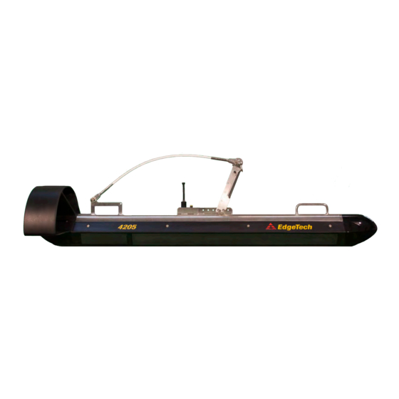
2-29 Figure 2-2: 4205 with 2Ft Depressor... -
Page 30: Electronic Bottle And Connection Drawings
RELIEF PORT TRANSDUCER PORTS PIN GUIDE: TRANSDUCER Pin 1: Shield SS TX-MP Pin 2: High Frequency + STBD Pin 3: High Frequency - Pin 4: Low Frequency + Pin 5: Low Frequency - Figure 2-3: 4205 MPMT Towfish Endcap Connections... -
Page 31: Figure 2-4: 4205 Tri-Frequency Endcap Connections
2-31 Figure 2-4: 4205 Tri-Frequency Endcap Connections... - Page 32 2-32 MAGNETOMETER CONNECTOR TOW CABLE CONNECTOR Figure 2-5: Tow Cable Connections...
-
Page 33: Figure 2-6: 4205 Mpmt And Tri-Frequency Tow Cable Connections With Pinouts
PIN 4: Not Connected PIN 4: SONAR RS232 RX from Mag PIN 5: Not Connected PIN 5: Return/RS-232 GND PIN 6: Not Connected PIN 6: TRIG-MAG PIN 7: 27VDC PIN 8: GND Figure 2-6: 4205 MPMT and Tri-Frequency Tow Cable Connections with Pinouts... - Page 34 2-34 Figure 2-7: 4205 MPMT and Tri-Frequency ROV Tow Cable Connections with Pinouts.
-
Page 35: Cable Drawings
2-35 2.5.3 Cable Drawings Diagrams of the optionally available cables are as follows: Figure 2-8: Kevlar 50m Reinforced Tow Cable... -
Page 36: Figure 2-9: Kevlar 150M Reinforced Tow Cable
2-36 Figure 2-9: Kevlar 150m Reinforced Tow Cable... -
Page 37: Figure 2-10: Armored 250M Tow Cable
2-37 Figure 2-10: Armored 250m Tow Cable... -
Page 38: Figure 2-11: Armored 500M Tow Cable
2-38 Figure 2-11: Armored 500m Tow Cable... -
Page 39: Technical Descriptions
(ADSL) modems in both the towfish and the topside electronics. The 4205 Towfish configurations are equipped with a stabilizer tail and a nose weighted for hydrodynamic balance. A towing arm is rigidly mounted to a tow point on the top of the towfish housing adjacent to the tow cable and option connectors. -
Page 40: Figure 3-1: 4205 Sp/Mpmt Towfish Diagram
3-40 Shear pin Tail cone Safety cable Towing arm Carrying Tow cable handle, one Options Connector Stainless steel connector forward and one housing Tow point Aft MP/RX transducer Forward SP/MP TX transducer Figure 3-1: 4205 SP/MPMT Towfish Diagram... -
Page 41: 4205 Tri-Frequency Towfish
Long-range operations can be achieved with a selection of 120/410 kHz combination, and then, on-demand, the 4205 can be changed to operate at 410/850kHz for a higher resolution survey. Target positioning is improved by integrating a more accurate heading sensor (AHRS) that can be coupled with an optional USBL beacon (such as EdgeTech’s BATS). -
Page 42: Figure 3-2: Typical 4205 System Diagram Using 1500M Tow Cable
3-42 Figure 3-2: Typical 4205 System Diagram using 1500m tow Cable... -
Page 43: Figure 3-3: 4205 Rack-Mounted System With The Directional Multi-Beacon Transponder/Responder Used With The Edgetech Usbl Bats
3-43 Figure 3-3: 4205 Rack-Mounted System with the Directional Multi-Beacon Transponder/Responder used with the EdgeTech USBL BATS... -
Page 44: Figure 3-4: Network Interface Diagram
3-44 Figure 3-4: Network Interface Diagram... -
Page 45: Setup And Activation
If the shipping containers appear free of damage, carefully unpack the components, and inspect them individually for damage. If any damage is found, report it to the carrier and EdgeTech. Also, check the packing list to verify that all the items on the list are included. If any items are missing, immediately contact EdgeTech. -
Page 46: Power Requirements
The 4205 Topsides and computers require 100–264 VAC, 50/60 Hz, and the systems’ voltage sense is auto- switching. Either the Starmux IV or 701-DL can power and interface to a 4205 and power a Magnetometer. Their difference is in the ability to support additional devices (optional) and long cables (up to 6000m in length). -
Page 47: Tcp/Ip Address Settings
19-inch rack front panel mounting hardware. 4.5 TCP/IP Address Settings The 4205 Side Scan Sonar System includes many Ethernet devices connected to a common local area network (LAN). Each of these devices has a factory set TCP/IP address, which does not require changing under normal circumstances. -
Page 48: Table 4-1: Edgetech Default Reserved Ip Numbers By System And Component
192.9.0.99 4205 + Starmux IV Preconfigured Topside CPU Wireless 192.9.0.100 4205 + Starmux IV Towfish CPU 192.9.0.101 4205 + Starmux IV Not Recommended 192.9.0.104-192.9.0.225 Table 4-1: EdgeTech Default Reserved IP Numbers By System and Component 4205 SIDE SCAN SYSTEM 0021769_REV_F... -
Page 49: Connecting The System Components
4-49 4.6 Connecting the System Components The 4205 standard system component configuration is as follows. The 4205 Towfish is physically connected to a Starmux or 701-DL digital link using a Kevlar or armored tow cable. The digital link is physically connected to a Discover-enabled computer utilizing Ethernet Ports on each via a CAT-5 Ethernet patch cable. -
Page 50: Connect And Attach The Tow Cable To The Towfish
Shear pin Main I/O Figure 4-3: 4205 Towfish with Armored Tow Cable 1. Verify that the tow cable is not connected to the topside processor. 2. Attach the tail cone to the Towfish and secure it with four hex socket bolts provided. -
Page 51: Installing A Depressor Wing And Connecting The Tow Cable
3. Connect the Ethernet patch cable to the DATA Ethernet Connector of the Starmux IV Digital Link and to the ethernet connector of the computer. If it is an EdgeTech 2U, connect to the right-side Ethernet Connector. Any Category 5 Ethernet patch cable can be used (max length = 100ft). -
Page 52: Connecting To The 4205 Rack Mount With Starmux Iv Dl
4-52 4.6.3.2 Connecting to the 4205 Rack Mount with Starmux IV DL IV 4205 R Refer to subsection for the location TARMUX OUNT ONTROLS NDICATORS ONNECTIONS of the connectors while performing the steps below: 1. Verify that the Starmux IV DL is not connected to AC power. -
Page 53: Connecting To The 4205 Rack Mount With 701-Dl
4-53 4.6.3.4 Connecting to the 4205 Rack Mount with 701-DL 701-DL 4205-R Refer to subsection for the location of OUNT ONTROLS NDICATORS ONNECTIONS the connectors while performing the steps below: 1. Verify that the 701-DL Rack Mount is not connected to AC power. -
Page 54: Activation, Test, And Deployment
5-54 5.0 ACTIVATION, TEST, AND DEPLOYMENT The 4205 can be activated after the connections to the Topside processor have been completed. However, a few pre-deployment checks are required before the deployment of the Towfish to verify that the system is operating properly. -
Page 55: Sbg Ahrs Usage
The introduction of the 4205 has given us an opportunity to improve the heading sensor's performance by fitting a MEMS-based inertial motion sensor unit that combines data from a built-in gyroscope, accelerometer, and magnetic field sensors using a Kalman filter algorithm. -
Page 56: Performing Pre-Deployment Checks
5-56 outputs. EdgeTech offers two options to configure this, with the first being preferred as there are fewer potential points of error. 1. The latitude and longitude that lie on one of the agonic lines (zero magnetic declination) will be entered prior to shipping the system. -
Page 57: Figure 5-2: Sidescan Control Tab In Discover 4205 Tri-Frequency
Figure 5-2: Sidescan Control Tab in Discover 4205 Tri-Frequency 3. Select the High Sonar On and Low Sonar On checkboxes for Discover 4205 MPMT, or any two of the Very High Frequency SONAR On, High Frequency SONAR On, and Low Frequency SONAR On checkboxes for Discover Tri-Frequency software. -
Page 58: Towfish Deployment
5.4 Towfish Deployment The 4205 Tri-Frequency or a MP/MT Towfish used in SP mode can be towed at speeds of up to 4.8 knots while still meeting NOAA and IHO-44S specifications of 3 pings on a 1-meter cubed target at 100 meters range. - Page 59 Verify that the towfish is as level as possible when towing it. For detailed towing characteristics for many tow cable types and lengths, along with • towfish speeds, with or without a depressor, refer to “Towing Characteristics for EdgeTech’s 4205 Towfish,” Revision 11. NOTE:...
- Page 60 Towfish remains at 10–15% of the range selection. 6. If a pressure sensor is installed, verify that the pressure display indication is correct. 7. Secure the tow cable to the survey vessel. 8. Begin recording data. 4205 SIDE SCAN SYSTEM 0021769_REV_F...
-
Page 61: Towfish Recovery
To recover the Towfish: 1. Slowly retrieve the tow cable until the Towfish is just below the surface. 2. Click the Towfish Control Tab (4205 MPMT) or Sidescan Control Tab (4205 Tri-Frequency) and deselect all Sonar checkboxes, shown in 5-2. -
Page 62: Maintenance
Towfish tow cable connector. Storage When not in use, all the components of the 4205 System should be packed in their original shipping containers in the same way they were originally shipped. Store equipment in a dry area when not in use. -
Page 63: Troubleshooting
By following the previous sections' instructions and performing regular maintenance, the user should seldom encounter bugs with the 4205 System. If problems do occur, however, this section will help users diagnose and fix simple bugs. It includes basic troubleshooting techniques and connector pin-out and wiring information to identify and correct possible setup or operational problems. -
Page 64: Figure 7-1: Tailfin Removal
Figure 7-1: Tailfin Removal 3. Pull the tail from the vehicle carefully. 4. The aft endcap should now be exposed. Carefully disconnect all of the transducer cables from their connectors. Figure 7-2: Aft Endcap Cable Disconnection 4205 SIDE SCAN SYSTEM 0021769_REV_F... -
Page 65: Figure 7-3: Side Seal Screw And Washer
7-65 5. Remove [2] screws and [2] finishing washers from both the forward and aft sides of the housing using a Phillips screwdriver. Figure 7-3: Side Seal Screw and Washer 6. Remove the nylon retaining lines from both the forward and aft side of the housing where the finishing screws and washers were removed. -
Page 66: Figure 7-5: Nose Cone Removal
7-66 Figure 7-5: Nose Cone Removal 8. The forward endcap is now exposed. Carefully disconnect all cables from their connectors. Figure 7-6: Forward Endcap Cable Disconnections 4205 SIDE SCAN SYSTEM 0021769_REV_F... -
Page 67: Figure 7-7: Aft Endcap Grip Handle Installation
7-67 9. Attach the EdgeTech supplied grip handle to the aft endcap by threading in the bolts. Figure 7-7: Aft Endcap Grip Handle Installation 10. Carefully pull the attached supplied grip handle to remove the electronics chassis from the housing and place it on a clean, dry and flat surface. -
Page 68: Assembling The Tow Vehicle
To assemble the tow vehicle, reverse the disassembly procedure. It is important to check and clean all O- ring surfaces before reassembling the vehicle. The O-ring surface should be free of any debris and only cleaned with a lint-free cloth. EdgeTech recommends that the O-rings should be greased and replaced to ensure a watertight seal. -
Page 69: Table 7-1: Troubleshooting Table
7-69 SYMPTOM PROBABLE CAUSE CORRECTIVE ACTION The tow cable between the digital link and the tow vehicle is Check connections and tow cable. disconnected or faulty. The green LINK indicator on the Starmux IV continues to flash after Modem settings on the digital link Contact CUSTOMER SERVICE several minutes, and no LINK is... -
Page 70: 4205 Rack Mount Troubleshooting Guide
Open Topside processor and check indicator and wiring. operating. Table 7-2: Rackmount Troubleshooting Chart Towfish Troubleshooting Guide The 4205 Towfish is a complex computer-controlled system that requires engineering expertise and the proper test equipment to service. For any service or troubleshooting, please contact EDGETECH CUSTOMER SERVICE for updated instructions, drawings, documentation, tools, and guidance. -
Page 71: 4205 Vehicle
OMMAND AND NOTE: It is recommended that all attempts be made to see if a problem is external to the Towfish before opening it. Also, contact EdgeTech to receive prior approval to open the Towfish chassis to avoid voiding the warranty. -
Page 72: Reported Errors
7.6.3 Transmission Verification The 4205 Towfish differs from older conventional side scan sonars in that the “listen for the clicking noise” test cannot be used to verify sonar transmission. Earlier sonars were driven using large transformer relays that made an audible sound when driven. -
Page 73: Topside Power Unit
Towfish. Data throughput rate can be checked using EdgeTech supplied utilities. The SockBlast application is used to test network throughput between the 4205 Towfish and the Topside computer. This application is normally kept in the C:\EdgeTech\Utilities folder on the Topside unit and D:\EdgeTech\Utilities folder on the Towfish. -
Page 74: Figure 7-9: Sockblast On Towfish Side
Towfish should increment from 0 to 1, and the Server count on the Topside should increment to 1 as well. This indicates one connection between the two applications. Check the Server Send Data box on the Towfish. A performance in MB/second will be displayed. This should be more than 0.35Mbyte/s. 4205 SIDE SCAN SYSTEM 0021769_REV_F... -
Page 75: Tow Cable Troubleshooting
7-75 Tow Cable Troubleshooting Historically, most system problems occur in the tow cable and their connectors. Before proceeding, verify cable continuity from the shipboard end of the cable to the towfish. The presence of a shorted or open wire in a tow cable can be determined by using a multi-meter. An open or shorted wire can be located using the techniques described in the following subsections. -
Page 76: Insulation Resistance Breakdown
Pin corrosion will start to occur as long as power is still applied. When detected, power should be immediately terminated at the topside to prevent further damage to the vehicle and crew members' safety during recovery. Any exposed electrical connections will require cleaning, re-termination. 4205 SIDE SCAN SYSTEM 0021769_REV_F... -
Page 77: 4205 Kits
This section contains labeled diagrams and Bills of Materials for spare and tool kits. A.1 4205 MPMT Spare Kits Images and BOMs are available on the following pages: 0020596 ASSY TOP KIT SPARES 4205 MP 100-400 KHZ TOW FISH Part Description ASSY SUB BOARDSET CPU MBT10 E3825 MINI PASSIVE HEATSINK ON 0018349 GIGABIT USB 3.0 CARRIER... - Page 78 7-78 0021509 ASSY TOP KIT SPARES 4205 MP 230-540 KHZ TOW FISH Part Description 0018349 ASSY SUB BOARDSET CPU MBT10 E3825 MINI PASSIVE HEATSINK ON GIGABIT USB 3.0 CARRIER 0006125 PCB ASSY POWER AMP ANALOG 4200 L IBERTY ENGINEERING 200-...
-
Page 79: Table 7-4: 4205 Mp 230-850 Khz Spare Kit
7-79 0021218 ASSY TOP KIT SPARES 4205 MP 230-850 KHZ TOW FISH Part Description ASSY SUB BOARDSET CPU MBT10 E3825 MINI PASSIVE HEATSINK ON 0018349 GIGABIT USB 3.0 CARRIER PCB ASSY POWER AMP ANALOG 4200 L IBERTY ENGINEERING 200- 0006125 0000040-1000"... -
Page 80: Table 7-5: 4205 Tri-Frequency 120/410/850 Spare Kit
7-80 A.2 4205 Tri-Frequency Spare Kits 0021880 ASSY TOP KIT SPARES 4205 TRIFREQUENCY 120 410 850 KHZ TOW FISH Part Description 0018349 ASSY SUB BOARDSET CPU MBT10 E3825 MINI PASSIVE HEATSINK ON GIGABIT USB 3.0 CARRIER 0021843 PCB ASSY TOP POWER AMP DUAL DIGITAL DDPA 120 KHZ RLJ1669... -
Page 81: Table 7-6: 4205 Tri-Frequency 120/540/850 Spares Kit
7-81 0021881 ASSY TOP KIT SPARES 4205 TRIFREQUENCY 230 540 850 KHZ TOW FISH Part Description 0018349 ASSY SUB BOARDSET CPU MBT10 E3825 MINI PASSIVE HEATSINK ON GIGABIT USB 3.0 CARRIER 0018384 PCB ASSY TOP POWER AMP DUAL DIGITAL DDPA 230 KHZ RLJ1212... -
Page 82: Table 7-7: 701 Digital Link Spare Kit
0006372 POWER SUPPLY CHASSIS CONVERTER AC-DC 115/230 INPUT 24 OUTPUT 0004228 CORD POWER 0003728 CIRCUIT PROTECT HOLDER FUSE 5X20MM 5A 250V FAST 0003669 CASE STORM 560 P / 566 P YELLOW Table 7-7: 701 Digital Link Spare Kit 4205 SIDE SCAN SYSTEM 0021769_REV_F... -
Page 83: Table 7-8: 4205 Tool Kit
0020969 TOOL HEX KEY BALL END T HANDLE 4MM 0006970 TOOL SCREWDRIVER PHILLIPS 01 0006968 TOOL PLIER W/SIDE CUTTERS 0019478 LABEL SHEET WHITE MAILING 04 INCH 1.33 INCH 0021213 DOC TEMPLATE 4205 HARDWARE / TOOLS KIT LABEL SET Table 7-8: 4205 Tool Kit...
Need help?
Do you have a question about the 4205 and is the answer not in the manual?
Questions and answers