Edgetech 4205 User Hardware Manual
Side scan system
Hide thumbs
Also See for 4205:
- User hardware manual (83 pages) ,
- Manual (35 pages) ,
- User hardware manual (86 pages)

Subscribe to Our Youtube Channel
Related Manuals for Edgetech 4205


Summary of Contents for Edgetech 4205
- Page 1 4205 SIDE SCAN SYSTEM U S E R H A R D W A R E M A N U A L 0021769_REV_D 6/22/2020 EdgeTech 4 Little Brook Road West Wareham, MA 02576 Tel: (508) 291-0057 Fax: (508) 291-2491 www.EdgeTech.com...
- Page 2 The information, figures, and specifications in this manual are proprietary. They are issued in strict confidence on condition that they not be copied, reprinted, or disclosed to a third party, either wholly or in part, without the prior written consent of EdgeTech. Any reproduction of EdgeTech supplied software or file sharing is strictly prohibited.
-
Page 3: Attention - Read This First
ATTENTION – READ THIS FIRST! All personnel involved with the installation, operation, or maintenance of the equipment described in this manual should read and understand the warnings and cautions provided below. CAUTION! This equipment contains devices that are extremely sensitive to static electricity. -
Page 4: Hardware Variations And Compatibility
HARDWARE VARIATIONS AND COMPATIBILITY The 4205 Side Scan system contains both standard and proprietary hardware. At times, EdgeTech may change the standard components due to their availability or performance improvements. Although the component manufacturers—along with their models and styles—may change from unit to unit, replacement parts will generally be interchangeable. -
Page 5: About This Document
Purpose of this Manual The purpose of this manual is to provide you with information on the setup and use of EdgeTech’s 4205. Although this manual encompasses the latest operational features of the 4205, some features may be periodically upgraded. -
Page 6: Warranty Statement
All equipment manufactured by EdgeTech is warranted against defective components and workmanship for a period of one year after shipment. Warranty repair will be done by EdgeTech free of charge. Shipping costs are to be borne by the customer. Malfunction due to improper use is not covered in the warranty, and EdgeTech disclaims any liability for consequential damage resulting from defects in the performance of the equipment. -
Page 7: Software Service Overview
Software Updates and Enhancements EdgeTech customers can download new software releases with all modifications and enhancements from the EdgeTech FTP site. Major software issues, should they occur, will be reported directly to the customer. New software releases consist of the following: •... -
Page 8: Returned Material Authorization
Refer to the RMA number on all documentation and correspondences. All returned materials must be shipped prepaid. Freight collect shipments will not be accepted. All equipment should be adequately insured for shipping, but equipment belonging to EdgeTech must be insured for full value. -
Page 9: Customer Service
CUSTOMER SERVICE Customer service personnel at EdgeTech are always eager to hear from you regarding our products. Your feedback is welcome and a valuable source of information that we use to improve products. Therefore, we encourage you to contact CUSTOMER SERVICE... -
Page 10: Company Background
— for the acquisition of underwater data, including marine, estuarine, and coastal applications — for over 50 years. EdgeTech responds to the needs of the scientific, naval, and offshore communities by providing industry- leading equipment — such as sub-bottom profilers, side-scan sonar, acoustic releases, USBL positioning systems, and bathymetric systems —... -
Page 11: Table Of Contents
COMPANY BACKGROUND ......................1-10 TABLE OF CONTENTS ........................1-11 LIST OF FIGURES ..........................1-15 LIST OF TABLES ..........................1-17 OVERVIEW ........................... 1-19 4205 Side Scan Sonar System Applications ................1-20 Main System Components ....................... 1-20 1.2.1 Topside Processor ....................... 1-20 1.2.2 Towfish.......................... - Page 12 Topside Technical Descriptions ....................3-48 3.2.1 Starmux IV Controls, Indicators and Connections .............. 3-48 3.2.2 Starmux IV 4205 Rack Mount Controls, Indicators, and Connections ........ 3-51 3.2.3 701-DL Controls, Indicators and Connections ..............3-55 3.2.4 701-DL 4205-Rack Mount Controls, Indicators, and Connections ........3-57 3.2.5...
- Page 13 Connecting to the Topside ....................4-77 4.6.3.1 Connecting to the Starmux IV DL ................4-77 4.6.3.2 Connecting to the 4205 Rack Mount with Starmux III DL .......... 4-77 4.6.3.3 Connecting to the 701-DL ................... 4-78 4.6.3.4 Connecting to the 4205 Rack Mount with 701-DL ............. 4-78 4.6.3.5...
- Page 14 1-14 701-DL Digital Link Troubleshooting Guide ................7-94 4205 Rack Mount (701-DL with 2U CPU) Troubleshooting Guide ........... 7-96 Starmux III Rack Mount (Starmux III DL with 2U CPU) Troubleshooting Guide ...... 7-96 Starmux III Digital Link Troubleshooting Guide ............... 7-96 Towfish Troubleshooting Guide ....................
-
Page 15: List Of Figures
Figure 2-5: Tow Cable Connections ......................2-36 Figure 2-6: 4205 MPMT and Tri-Frequency Tow Cable Connections with Pinouts ......... 2-37 Figure 2-7: 4205 MPMT and Tri-Frequency ROV Tow Cable Connections with Pinouts......2-38 Figure 2-8: Starmux IV ICD ........................2-43 Figure 2-9: Starmux IV DL in Case ...................... - Page 16 Figure 3-12: Starmux III Back Panel ......................3-64 Figure 3-13: 4205 Rack Mount Topside Processor Front Panel ............... 3-67 Figure 3-14: 4205 Starmux III Rack Mount Topside Processor Rear Panel ..........3-68 Figure 3-15: 4205 System Diagram ......................3-69 Figure 3-16: Example of 4205 Rack Mount System with the Directional Multi-Beacon Transponder/Responder used with the EdgeTech USBL BATS ..............
- Page 17 Table 7-8: 4205 MPMT 230-850 kHz Spare Kit ..................A-105 Table 7-9: 4205 MP 230-530 kHz Spare Kit ................... A-106 Table 7-10: 4205 Tri-Frequency 120/410/850 Spare Kit............... A-106 Table 7-11: 4205 Tri-Frequency 120/540/850 Spares Kit701-DL Spare Kit .......... A-107 Table 7-12: 701 Digital Link Spare Kit ....................A-107...
- Page 18 1-18 Table 7-13: 4205 Tool Kit ........................A-108 4205 SIDE SCAN SYSTEM 0021769_REV_D...
-
Page 19: Overview
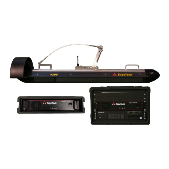
1-19 1.0 OVERVIEW The next-generation 4205 is a versatile side scan sonar system that can be configured for almost any survey application from shallow to deepwater operations. The 4205 utilizes EdgeTech’s Full Spectrum® CHIRP technology to provide crisp, high-resolution imagery at ranges up to 50% greater than non-CHIRP systems, thus allowing customers to cover larger areas and save money spent on costly surveys. -
Page 20: 4205 Side Scan Sonar System Applications
Search and recovery • Archeological surveys 1.2 Main System Components The 4205 High Definition Tri-Frequency Side Scan Sonar System is made up of 3 main components: • Topside processor (Two types are available: 701-DL, Starmux IV, and rack-mounted versions of both.) •... -
Page 21: Figure 1-1: Starmux Iv Rackmount With Keyboard, Mouse And Lcd Monitor
Keyboard o Trackball o LCD Monitor The 4205-Portable Topside and 4205-Rack Mount each include a computer with Windows 10 and EdgeTech’s Discover Software. The 701-DL and Starmux III Digital Links are used with a user-supplied computer, running Discover or third- party data acquisition and display software. -
Page 22: Figure 1-2: 701-Dl Rack Mount With Keyboard, Trackball, And Lcd Monitor
1-22 Figure 1-2: 701-DL Rack Mount with Keyboard, Trackball, and LCD Monitor Figure 1-3: Starmux Rackmount with Keyboard, Trackball Mouse, and Display 4205 SIDE SCAN SYSTEM 0021769_REV_D... -
Page 23: Towfish
1-23 1.2.2 Towfish The 4205 Towfish comes in standard tow or ROV tow with Multi-Pulse or Tri Frequency Sonar configurations. 4205 TRI-FREQUENCY 4205 TRI-FREQUENCY 4205 MPMT 4205 MPMT ROV 120/410/850 kHz 120-410 kHz 120/410/850 kHz 120-410 kHz 230/540/850 kHz 230-540 kHz... -
Page 24: Tow Cables
A cable grip is included for attaching the tow cable to the towing arm of the towfish. Figure 1-7: Kevlar Tow Cable 1.3 Optional Equipment The following optional equipment can be installed and used with the 4205 High Definition Dual-frequency Side Scan Sonar System: •... -
Page 25: Sgb Compass
The EdgeTech Depressor Wing allows the towfish to be towed at greater depths and faster speeds without increasing the length of tow cable in the water. The depressor wing attaches to the top of any 4205 towfish and exerts a downward force on the towfish as it moves through the water, pushing it deeper. The angle of the wing is adjustable to 0°, 5°, or 10°, depending on the desired dive angle. -
Page 26: Specifications
2-26 2.0 SPECIFICATIONS The specifications for the standard EdgeTech 4205 High Definition Dual-Frequency Side Scan Sonar System are described below. These may vary depending on customized system orders and should be used as a reference. For detailed information regarding custom systems, refer to the Custom system addendum or... -
Page 27: Towfish Specifications
52 kg (115 pounds) Weight in saltwater: 36 kg (80 lb) Construction: Stainless steel Maximum tow cable length: 6000 m (19,680 ft) Contact EdgeTech for cable type vs. length. Depth rating: 2000 m (6560 ft) Tow cable type: Coaxial Shear pin type: 8 mm (5/16 in.) Delrin rod... -
Page 28: Table 2-3: Starmux Iv Specifications
High impact industrial trackball External trigger (4) Ethernet (5) Ethernet (6) RS-232 (8) RS-232 (1)PPS Trigger (6) USB 2 I/O ports (1)FSK Trigger (2) USB 3 (2)Trigger (1)PPS Trigger (1)FSK Trigger (2) Trigger Table 2-3: Starmux IV Specifications 4205 SIDE SCAN SYSTEM 0021769_REV_D... - Page 29 2-29 701-DL DIGITAL LINK (IN 2U-SKB CASE) RACK MOUNT (701-DL AND 2U COMPUTER IN 6U CASE) With 2U-SKB Case: 17.8 cm (7 in.) high 15.75 cm (6.20 in.) high 43.2 cm (17 in.) wide 56.90 cm (22.40 in) wide. 45.7 cm (19 in.) deep 60.96 cm (24 in.) wide Size Without Case:...
-
Page 30: Table 2-4: 701-Dl Specification
4 GB, 1333 MHz — DVD/RW drive Data storage 1-TB hard drive (data) 500-GB hard drive (OS) Display — 21-inch LCD monitor Keyboard — High impact industrial keyboard Pointing device — High impact industrial trackball External trigger 4205 SIDE SCAN SYSTEM 0021769_REV_D... -
Page 31: Kevlar Tow Cable Specifications
A cable grip is included for attaching the tow cable to the towing arm of the tow vehicle. Specifications for the 4205 tow cable options, along with the power cables, are provided in the drawings that follow. -
Page 32: Mechanical Drawings
2-32 2.4 Mechanical Drawings Mechanical Drawing of the towfish and tow cable connections are provided on the following pages: 2.4.1 4205 Towfish Drawings Figure 2-1: 4205 Towfish ICD – 0020967... -
Page 33: Figure 2-2: 4205 With 2Ft Depressor - 0021208
2-33 Figure 2-2: 4205 with 2Ft Depressor – 0021208... -
Page 34: Electronic Bottle And Connection Drawings
2-34 2.4.2 Electronic Bottle and Connection Drawings Pressure Sensor Port TRANSDUCER SS RX-MP TRANSDUCER STBD SS TX-MP PORT Pressure Relief Port TRANSDUCER SS RX-MP PORT TRANSDUCER SS TX-MP STBD Figure 2-3: 4205 MPMT Towfish Endcap Connections... -
Page 35: Figure 2-4: 4205 Mpmt Tri-Frequency Endcap Connections
2-35 Figure 2-4: 4205 MPMT Tri-Frequency Endcap Connections... - Page 36 2-36 MAGNETOMETER CONNECTOR TOW CABLE CONNECTOR Figure 2-5: Tow Cable Connections...
-
Page 37: Figure 2-6: 4205 Mpmt And Tri-Frequency Tow Cable Connections With Pinouts
PIN 2: Return/RS-232 GND PIN 3: Side-Scan TX to Mag (RS232) PIN 4: Side-Scan RX from Mag TX(RS-232) PIN 5: Return/RS-232 GND PIN 6: TRIG-MAG PIN 7: 27VDC PIN 8: GND Figure 2-6: 4205 MPMT and Tri-Frequency Tow Cable Connections with Pinouts... - Page 38 2-38 Figure 2-7: 4205 MPMT and Tri-Frequency ROV Tow Cable Connections with Pinouts.
-
Page 39: Cable Drawings
2-39 2.4.3 Cable Drawings Diagrams of the optionally available cables are as follows: Figure A-1: Kevlar 150m Reinforced Tow Cable ICD – 0002957... - Page 40 2-40 Figure A-2: Armored 250m Tow Cable ICD – 0020924...
- Page 41 2-41 Figure A-3: Armored 500m Tow Cable ICD – 0020314...
- Page 42 2-42 Figure A-4: AC Power Cable – 0002868...
-
Page 43: Topside Digital Link Drawings
2-43 2.4.4 Topside Digital Link Drawings Figure 2-8: Starmux IV ICD... -
Page 44: Figure 2-9: Starmux Iv Dl In Case
2-44 Figure 2-9: Starmux IV DL in Case... -
Page 45: Figure 2-10: 701 Dl
2-45 Figure 2-10: 701 DL... -
Page 46: Technical Descriptions
(ADSL) modems in both the towfish and the processor. The 4205 Towfish configurations are equipped with a stabilizer tail and a nose weighted for hydrodynamic balance. A towing arm is rigidly mounted to a tow point on the top of the towfish housing adjacent to the tow cable and option connectors. -
Page 47: 4205 Tri-Frequency & Single Pulse Towfish
Long-range operations can be achieved with a selection of 120/410 kHz combination and then, on-demand, the 4205 can be changed to operate at 410/850kHz for a higher resolution survey. Target positioning is improved with the integration of a more accurate heading sensor that can be coupled with an optional USBL beacon. -
Page 48: Topside Technical Descriptions
3.2 Topside Technical Descriptions Edgetech Topside digital links provide power to the towfish while acting as a digital link between the towfish and a topside computer with EdgeTech’s Discover application installed on it. Discover provides the ability to monitor and control towfish systems and process and record sonar data. The digital link also provides input connections for supporting survey, navigation devices, and triggers. -
Page 49: Table 3-1: 701-Dl Controls, Indicators, And Connections
3-49 1PPS Connector Pulse per second connector. Trigger Connectors (2) Optional digital ports provided for triggers. Serial Com Ports (6) Serial ports for external device connections. Table 3-1: 701-DL Controls, Indicators, and Connections... -
Page 50: Figure 3-2: Starmux Iv Front And Back Panels
3-50 Digital Display Starmux Power Switch Indicator Lights NAV Input for Network Broadcast Telemetry/Subsea Serial Ports Fuses 1PPS Connection Power Switch Sea Cable Connector Grounding Optional Trigger Connectors FSK Sync Network Ethernet Ports Connector Figure 3-2: Starmux IV Front and Back Panels... -
Page 51: Starmux Iv 4205 Rack Mount Controls, Indicators, And Connections
3-51 3.2.2 Starmux IV 4205 Rack Mount Controls, Indicators, and Connections FRONT PANEL STARMUX IV Rocker switch. Turns the Starmux Digital Link on or off. The rear line Starmux IV Power Switch power switch needs to be turned on for this switch to function. -
Page 52: Table 3-2: Starmux Iv Rack Mount Controls, Indicators, And Connections
DB-9 female connector. RS-232 serial port that connects to the navigation COM-1 NAV Connector system when the Starmux IV is not used. COM-3 Connector DB-9 female connector. General-purpose RS-232 serial port. Table 3-2: Starmux IV Rack Mount Controls, Indicators, and Connections 4205 SIDE SCAN SYSTEM 0021769_REV_D... -
Page 53: Figure 3-3: Labeled Front Panels Of 2300 Rackmount
3-53 Digital Display Starmux Power Switch Indicator Lights DVD/RW Drive USB Connectors Figure 3-3: Labeled Front Panels of 2300 Rackmount... -
Page 54: Figure 3-4: Labeled Rear Picture Of 2300 Rackmount
3-54 NAV Input for Network Broadcast Fuses Network Ethernet Ports Telemetry/Subsea Serial Ports 1PPS Connector Power Switch Sea Cable Connector Grounding Video Card Optional Trigger Connectors FSK Sync Connector Power Switch USB Connectors PC COM-1 PC COM-3 Network Ethernet Ports Figure 3-4: Labeled Rear Picture of 2300 Rackmount... -
Page 55: 701-Dl Controls, Indicators And Connections
3-55 3.2.3 701-DL Controls, Indicators and Connections The 701-DL's (digital link) controls, indicators, and connections are described below: FRONT PANEL Power Switch This rocker switch turns the 701-DL Link on or off. Green indicator. Flashes continuously when an Ethernet connection is LAN Indicator Light established. -
Page 56: Figure 3-5: 701-Dl Front And Back Panels
3-56 POWER Switch LAN, LINK, FISH POWER and POWER indicators LINE VAC connector, DATA SEA CABLE Switch, and AC Fuse connector connector GROUNDING SYNC connector Figure 3-5: 701-DL Front and Back Panels... -
Page 57: 701-Dl 4205-Rack Mount Controls, Indicators, And Connections
3-57 3.2.4 701-DL 4205-Rack Mount Controls, Indicators, and Connections The 4205-Rack Mount (701-DL and 2U-CPU Combo) controls, indicators, and connections are described below: FRONT PANEL 701-DL Power Switch Rocker switch. Turns the 701-DL Link on or off. Green indicator. Flashes continuously when an Ethernet connection is LAN Indicator Light established. -
Page 58: Figure 3-6: 4205 Rack Mount Topside Processor Front Panel
3-58 POWER switch SYSTEM POWER indicator LINK indicator LAN indicator FISH POWER DVD drive USB connectors Figure 3-6: 4205 Rack Mount Topside Processor Front Panel... -
Page 59: Figure 3-7: 4205 Rack Mount Topside Processor Rear Panel
3-59 ETHERNET connector SEA CABLE connector VAC INPUT connector SYNC connector POWER switch COM 1-NAV connector ETHERNET connector Video Card VAC INPUT connector POWER switch USB connectors Figure 3-7: 4205 Rack Mount Topside Processor Rear Panel... -
Page 60: Figure 3-8: 4205 System Diagram
3-60 Figure 3-8: 4205 System Diagram... -
Page 61: Figure 3-9: Example Of 4205 Rack Mount System With The Directional Multi-Beacon
3-61 Figure 3-9: Example of 4205 Rack Mount System with the Directional Multi-Beacon Transponder/Responder used with the EdgeTech USBL BATS... -
Page 62: Figure 3-10: 4205 Topside Block Diagram
3-62 Figure 3-10: 4205 Topside Block Diagram... -
Page 63: Starmux Iii Controls, Indicators And Connections
3-63 3.2.5 Starmux III Controls, Indicators and Connections The Starmux III (digital link) controls, indicators, and connections are described below: Note: The Starmux IV has replaced the Starmux III. This section is included only to support systems sold with the Starmux III. FRONT PANEL Rocker switch. -
Page 64: Figure 3-11 Starmux Iii Front Panel
3-64 Power Switch LAN, Link, Fish Power and Starmux Power Indicators Figure 3-11 Starmux III Front Panel AC Fuse Line Power Switch Grounding Lug 2.5A Fuse Sea Cable Connector Data Connector Sync Connector Line VAC Connector Figure 3-12: Starmux III Back Panel... -
Page 65: Starmux Iii-4205 Rack Mount Controls, Indicators, And Connections
3-65 3.2.6 Starmux III-4205 Rack Mount Controls, Indicators, and Connections The 4205-Rack Mount (Starmux and 2U-CPU Combo) controls, indicators, and connections are described below: Note: The Starmux IV has replaced the Starmux III. This section is included only to support systems sold with the Starmux III. -
Page 66: Table 3-6: Starmux Iii Rack Mount Controls, Indicators And Connections
Located on CPU. DB-9 female connector. RS-232 serial port that can be used to connect to COM-3 Connector the navigation system. Located on CPU. Table 3-6: Starmux III Rack Mount Controls, Indicators and Connections 4205 SIDE SCAN SYSTEM 0021769_REV_D... -
Page 67: Figure 3-13: 4205 Rack Mount Topside Processor Front Panel
3-67 SEA CABLE connector Starmux III Power Switch LAN Indicator Light Starmux III Power Indicator Light LNK Indicator Light Fish Power Indicator Light DVD Drive USB Connectors Figure 3-13: 4205 Rack Mount Topside Processor Front Panel... -
Page 68: Figure 3-14: 4205 Starmux Iii Rack Mount Topside Processor Rear Panel
Data Connector Sync Connector 2.5A Fuse COM 3-NAV connector Starmux Line COM 1-NAV connector VAC Connector ETHERNET connector Video Card USB Connectors Computer VAC INPUT CPU POWER Switch Connector Figure 3-14: 4205 Starmux III Rack Mount Topside Processor Rear Panel... -
Page 69: Figure 3-15: 4205 System Diagram
3-69 Figure 3-15: 4205 System Diagram... -
Page 70: Figure 3-16: Example Of 4205 Rack Mount System With The Directional Multi-Beacon
3-70 Figure 3-16: Example of 4205 Rack Mount System with the Directional Multi-Beacon Transponder/Responder used with the EdgeTech USBL BATS... -
Page 71: Figure 3-17: 4205 Starmux Iii Topside Block Diagram
3-71 COMPUTER NETWORK LAN ADSL MODEM ETHERNET ETHERNET 192.9.0.99 192.9.0.22 ADSL SEA CABLE ADSL FSIU PCB ADSL INTERFACE TOW VEHICLE (FSIC) SEA CABLE (ADSL) ADSL MODEM TOPSIDE SONAR PROCESSOR 192.9.0.101 Figure 3-17: 4205 Starmux III Topside Block Diagram... -
Page 72: Setup And Activation
If any damage is found, report it to the carrier and EdgeTech. Also, check the packing list to verify that all the items on the list are included. If any items are missing, immediately contact EdgeTech. -
Page 73: Digital Link Systems
Store the system in a dry environment when not in use. 4.2 Power Requirements The power requirements for the 4205 Topside processors are 100–264 VAC, 50/60 Hz, and is auto- switching. 4.2.1 Use of an Uninterrupted Power Supply The AC power source should be continuously free of high amplitude, high-frequency transients, as this type of interference could degrade performance or damage the equipment. -
Page 74: Change To A Non-Us Power Plug
(GPS) or integrated navigation system. 4.4 Topside Processor Placement The 4205 Rack Mount Topside Processor with the Digital Link should be located and set up in a dry, sheltered area that is protected from weather and water spray. Both units also require an environment where the temperature is consistently between 0°C and 40°C (32°F and 104°F). -
Page 75: Tcp/Ip Address Settings
4-75 4.5 TCP/IP Address Settings The 4205 high Definition Dual-frequency Side Scan Sonar System includes many Ethernet devices connected on a common local area network (LAN). Each of these devices has a factory set TCP/IP address, which under normal circumstances does not require changing. -
Page 76: Connect And Attach The Tow Cable To The Towfish
Tie wrap Shear pin Figure 4-1: 4205 Towfish with Armored Tow Cable 1. Verify that the tow cable is not connected to the topside processor. 2. Attach the tail cone to the towfish and secure with four hex socket bolts provided. -
Page 77: Installing A Depressor Wing And Connecting The Tow Cable
Starmux III. Refer to subsection IV 4205 R for the location TARMUX OUNT ONTROLS NDICATORS ONNECTIONS of the connectors while performing the steps below: 1. Verify that the 4205 Rack Mount is not connected to AC power. -
Page 78: Connecting To The 701-Dl
Connecting to the 4205 Rack Mount with 701-DL Refer to subsection 701-DL 4205-R for the location of OUNT ONTROLS NDICATORS ONNECTIONS the connectors while performing the steps below: 1. Verify that the 4205 Rack Mount is not connected to AC power. 4205 SIDE SCAN SYSTEM 0021769_REV_D... -
Page 79: Connecting To The Starmux Iii Dl
6. If a navigation system will be used, connect the navigation system output to the COM 1 connector. 7. If an external source will be used to trigger the 4205 701-DL with 2U CPU, connect the trigger output of this source to the EXT TRIG connector. -
Page 80: Connecting To The 4205 Rack Mount With Starmux Iii Dl
ONNECTIONS of the connectors while performing the steps below: 1. Verify that the 4205 Rack Mount is not connected to AC power. 2. Verify that the tow cable is properly connected and attached to the towfish, and then connect the tow cable to the SEA CABLE connector. -
Page 81: Activation, Test, And Deployment
5-81 5.0 ACTIVATION, TEST, AND DEPLOYMENT The 4205 can be activated after the connections to the topside processor have been completed. However, a few pre-deployment checks are required before the deployment of the Towfish to verify that the system is operating properly. -
Page 82: Activating A Starmux Iii System
Do not allow the transducer arrays on the towfish to continuously transmit in the air for an extended period, as damage to the transducer arrays could occur. 2. In Discover, click the Towfish Control (4205MPMT) or Sidescan Control (4205 Tri-Frequency) tab in the Lower Control panel, shown in 5-2. -
Page 83: Figure 5-1: Towfish Control Tab In Discover 4205 Mpmt
Figure 5-2: Sidescan Control Tab in Discover 4205 Tri-Frequency 3. Select the High Sonar On and Low Sonar On checkboxes for Discover 4205 MPMT, or the Very High Frequency On, High Frequency On and Low Frequency On checkboxes for Discover Tri- Frequency software. -
Page 84: Towfish Deployment
5.3 Towfish Deployment The 4205-SP Towfish can be towed at speeds of up to 4.8 knots while still meeting NOAA and IHO-44S specifications of 3 pings on a 1-meter cubed target at 100 meters range. The 4205-MP Towfish can be towed at speeds of up to 9.6 knots with the same results when operating in HSM. -
Page 85: Towfish Recovery
NOTE: For detailed information about the Discover software, including how to record data, refer to the Discover 4205 Software Manuals. To Deploy the Towfish: 1. With the survey vessel underway at up to two knots, slowly and carefully lower the towfish into the water, well away from the propeller. -
Page 86: Figure 5-4: 4205 Towfish
1. Slowly retrieve the tow cable until the towfish is just below the surface. 2. Click the Towfish Control Tab (4205 MPMT) or Sidescan Control Tab (4205 Tri-Frequency) and deselect the High Sonar On and Low Sonar On checkboxes, shown in 5-2. -
Page 87: Maintenance
Towfish tow cable connector. Storage When not in use, all the components of the 4205 System should be packed in their original shipping containers in the same way they were originally shipped. Store equipment in a dry area when not in use. -
Page 88: Troubleshooting
By following the instructions in the previous sections and performing regular maintenance, the user should seldom encounter bugs with the 4205 System. If problems do occur, however, this section will help users diagnose and fix simple bugs. It includes basic troubleshooting techniques, along with connector pin-out and wiring information, to assist in identifying and correcting possible setup or operational problems. -
Page 89: Figure 7-1: Tailfin Removal
7-89 Figure 7-1: Tailfin Removal 3. Pull the tail from the vehicle carefully. 4. The aft endcap should now be exposed. Carefully disconnect all of the transducer cables from their connectors. Figure 7-2: Aft Endcap Cable Disconnection... -
Page 90: Figure 7-3: Side Seal Screw And Washer
It may be necessary to push on the endcap for leverage to remove the line. Installing the supplied grip can facilitate this (see STEP Figure 7-4: Nylon Retaining Line Removal 4205 SIDE SCAN SYSTEM 0021769_REV_D... -
Page 91: Figure 7-5: Nose Cone Removal
7-91 7. Carefully remove the nose cone by pulling it from the vehicle. Figure 7-5: Nose Cone Removal 8. The forward endcap is now exposed. Carefully disconnect all cables from their connectors. Figure 7-6: Forward Endcap Cable Disconnections... -
Page 92: Figure 7-7: Aft Endcap Grip Handle Installation
7-92 9. Attach the Edgetech supplied grip to the aft endcap by threading in the bolts. Figure 7-7: Aft Endcap Grip Handle Installation 10. Carefully pull the attached supplied grip to remove the electronics chassis from the housing and place it on a clean, dry, flat surface. -
Page 93: Assembling The Tow Vehicle
To assemble the tow vehicle, reverse the disassembly procedure. 7.3 Standard Compass Calibration (AHRS Compass) The compass is calibrated at the EdgeTech manufacturing facility and should not require additional CUSTOMER calibration. Should the compass in the Towfish lose its calibration for any, please contact SERVICE to recalibrate it. -
Page 94: 701-Dl Digital Link Troubleshooting Guide
Check LAN connections between topside and indicator on the the topside and the computer. laptop. topside does not Open the topside processor and check the indicator The indicator is not operating. illuminate when the and wiring. 4205 SIDE SCAN SYSTEM 0021769_REV_D... -
Page 95: Table 7-2: 701-Dl Digital Link Troubleshooting Guide
Modem settings on the topside Refer to APPENDIX C for modem settings. turned on. After 1- are incorrect. minute flashing should Check topside on different Towfish. stop, and the indicator 4205 Towfish is faulty. should remain lit. Table 7-2: 701-DL Digital Link Troubleshooting Guide. -
Page 96: 4205 Rack Mount (701-Dl With 2U Cpu) Troubleshooting Guide
7-96 7.6 4205 Rack Mount (701-DL with 2U CPU) Troubleshooting Guide This troubleshooting section is for the 701-DL and Computer Combo. SYMPTOM PROBABLE CAUSE CORRECTIVE ACTION The POWER switch is not Verify that the POWER switch located in rear off CPU is in turned on. - Page 97 7-97 SYMPTOM PROBABLE CAUSE CORRECTIVE ACTION The POWER switch in the front Verify that both POWER or rear of the unit is not turned switches are on. Verify that the digital link is No AC power. When using the connected to AC power. Check AC power connector.
-
Page 98: Towfish Troubleshooting Guide
Table 7-5: Starmux III Troubleshooting Guide Towfish Troubleshooting Guide The 4205 Towfish is a complex computer-controlled system that requires engineering expertise and the proper test equipment to service. For any service or troubleshooting, please contact EDGETECH CUSTOMER SERVICE for updated instructions, drawings, documentation, tools, and guidance. -
Page 99: Required Equipment
These tones are generated in the software of the 4205 Towfish and are replicated on the surface when an EdgeTech topside processor is used to access the Towfish computer subsystem using the Remote Desktop application. -
Page 100: Topside Power Unit
Data throughput rates on the uplink (fish to topside) can be critical in getting smooth data from the towfish. Data throughput rate can be checked using EdgeTech supplied utilities at each end of the link. The SockBlast application is used to test network throughput between the 4205 Towfish and the topside computer. -
Page 101: Figure 7-9: Sockblast On Towfish Side
7-101 1. Set the IP address of the server to match the IP address of the desktop computer (192.9.0.99), then press, create server. 2. Check “Send Data from Server to Client” this will start the process of sending data Figure 7-9: sockBlast on Towfish Side From Topside Computer 3. -
Page 102: Towfish
NOTE: It is recommended that all attempts be made to see if a problem is external to the Towfish before opening it. Also, contact EdgeTech to receive prior approval to open the towfish chassis so as not to risk voiding the warranty. -
Page 103: Tow Cable Troubleshooting
7-103 7.10 Tow Cable Troubleshooting Historically, most system problems occur in the tow cable and their connectors. Before proceeding, verify cable continuity from the shipboard end of the cable to the towfish. The presence of a shorted or open wire in a tow cable can be determined by using a multi-meter. An open or shorted wire can be located using the techniques described in the following subsections. -
Page 104: Insulation Resistance Breakdown
If the power is not immediately removed, and the cable is not immediately retrieved, and the connector flushed out with freshwater, there may be permanent damage to the connector. This will require cable re-termination. 4205 SIDE SCAN SYSTEM 0021769_REV_D... -
Page 105: 4205 Kits
This section contains labeled diagrams and Bills of Materials for spare and tool kits. A.1 4205 MPMT Spare Kits Images and BOMs are available on the following pages: 0020596 ASSY TOP KIT SPARES 4205 MP 100-400 KHZ TOW FISH Part Description ASSY SUB BOARDSET CPU MBT10 E3825 MINI PASSIVE 0018349 HEATSINK ON GIGABIT USB 3.0 CARRIER... -
Page 106: 4205 Tri-Frequency Spare Kits
0023061 PCB ASSY TOP INTERFACE MESTECH MODEM TDSL 1006 Table 7-9: 4205 MP 230-530 kHz Spare Kit A.2 4205 Tri-Frequency Spare Kits 0021880 ASSY TOP KIT SPARES 4205 TRIFREQUENCY 120 410 850 KHZ TOW FISH Part Description 0018349 ASSY SUB BOARDSET CPU MBT10 E3825 MINI PASSIVE HEATSINK ON GIGABIT USB 3.0 CARRIER... -
Page 107: Tool Kits
A-107 0021881 ASSY TOP KIT SPARES 4205 TRIFREQUENCY 230 540 850 KHZ TOW FISH 0018384 PCB ASSY TOP POWER AMP DUAL DIGITAL DDPA 230 KHZ RLJ1212 6000M 0021680 PCB ASSY TOP SONAR INTERFACE MODULE II SIM2 4205 540KHZ - 850KHZ... - Page 108 0020480 ASSY SUB KIT 4205 HARDWARE/TOOLS 0006968 TOOL PLIER W/SIDE CUTTERS 0019478 LABEL SHEET WHITE MAILING 04 INCH 1.33 INCH 0021213 DOC TEMPLATE 4205 HARDWARE / TOOLS KIT LABEL SET Table 7-13: 4205 Tool Kit 4205 SIDE SCAN SYSTEM 0021769_REV_D...
Need help?
Do you have a question about the 4205 and is the answer not in the manual?
Questions and answers