Sign In
Upload
Manuals
Brands
Edge-Core Manuals
Switch
ECS4510-52P
Edge-Core ECS4510-52P Manuals
Manuals and User Guides for Edge-Core ECS4510-52P. We have
2
Edge-Core ECS4510-52P manuals available for free PDF download: Installation Manual
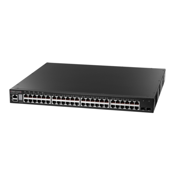
Edge-Core ECS4510-52P Installation Manual (90 pages)
28/52-Port Layer 2+ Stackable GE Switch
Brand:
Edge-Core
| Category:
Switch
| Size: 4 MB
Table of Contents
Compliances and Safety Statements
5
About this Guide
15
Table of Contents
17
Contents
17
Tables
19
Figures
21
Introduction
23
Overview
23
Figure 1: 28-Port Switch Front Panels
23
Figure 2: 52-Port Switch Front Panels
24
Figure 3: Rear Panel
24
Description of Hardware
26
Table 1: Port Status Leds
27
Figure 4: Port Leds
27
Table 2: System Status Leds
28
Figure 5: System Leds
28
Figure 6: Power Supply Sockets
29
Figure 7: Dual-Port 10GBASE Module (SFP+)
29
Network Planning
31
Introduction to Switching
31
Application Examples
32
Figure 8: Poe Connections
32
Figure 9: Collapsed Backbone
33
Figure 10: Network Aggregation Plan
34
Figure 11: Remote Connections with Fiber Cable
35
Figure 12: Making VLAN Connections
36
Application Notes
37
Installing the Switch
39
Selecting a Site
39
Ethernet Cabling
40
Equipment Checklist
41
Mounting
42
Figure 14: Attaching the Brackets
43
Figure 15: Installing the Switch in a Rack
43
Figure 16: Attaching the Adhesive Feet
44
Installing an Optional Module into the Switch
45
Figure 17: Installing an Optional Module
45
Installing an SFP or SFP+ Transceiver
46
Table 3: Optional Transceivers
46
Figure 18: Inserting an SFP Transceiver into a Slot
46
Connecting Switches in a Stack
47
Figure 19: Making Stack Connections
48
Connecting to a Power Source
49
Figure 20: Power Socket
49
Connecting to the Console Port
50
Table 4: Serial Cable Wiring
50
Figure 21: Serial Port (RJ-45) Pin-Out
50
Making Network Connections
53
Connecting Network Devices
53
Twisted-Pair Devices
53
Figure 22: Making Twisted-Pair Connections
54
Figure 23: Network Wiring Connections
55
Fiber Optic SFP Devices
56
Figure 24: Making Fiber Port Connections
57
Gbps Fiber Optic Connections
58
10 Gbps DAC Connections
59
Connectivity Rules
60
Table 5: Maximum 1000BASE-SR Gigabit Ethernet Cable Lengths
60
Table 6: Maximum 10GBASE-LR 10 Gigabit Ethernet Cable Length
60
Table 7: Maximum 10GBASE-ER 10 Gigabit Ethernet Cable Length
61
Table 8: Maximum 10GBASE-CR 10 Gigabit Ethernet Cable Lengths
61
Table 9: Maximum 1000BASE-T Gigabit Ethernet Cable Length
61
Table 10: Maximum 1000BASE-SX Gigabit Ethernet Cable Lengths
61
Table 11: Maximum 1000BASE-LX Gigabit Ethernet Cable Length
61
Cable Labeling and Connection Records
62
Table 12: Maximum 1000BASE-ZX Gigabit Ethernet Cable Length
62
Table 13: Maximum Fast Ethernet Cable Lengths
62
Table 14: Maximum Ethernet Cable Length
62
A Troubleshooting
65
Diagnosing Switch Indicators
65
Table 15: Troubleshooting Chart
65
Power and Cooling Problems
66
Installation
66
Table 16: Power/Rps Leds
66
In-Band Access
67
Cables
69
Twisted-Pair Cable and Pin Assignments
69
Table 17: 10/100BASE-TX MDI and MDI-X Port Pinouts
70
Figure 26: Straight-Through Wiring
71
Figure 27: Crossover Wiring
71
Table 18: 1000BASE-T MDI/MDI-X Port Pinouts
72
Fiber Standards
73
Table 19: Fiber Standards
73
Specifications
75
Physical Characteristics
75
Switch Features
77
Management Features
78
Standards
78
Compliances
78
10GBASE-SFP+ Extender Module
79
Redundant Power Supply
80
Glossary
81
Index
87
Advertisement
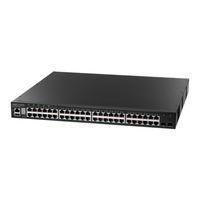
Edge-Core ECS4510-52P Installation Manual (58 pages)
28/52-Port Layer 2+ Stackable GE Switch
Brand:
Edge-Core
| Category:
Switch
| Size: 3 MB
Table of Contents
How to Use this Guide
3
Table of Contents
6
Contents
6
Figures
8
Tables
10
Switch Description
11
Overview
11
Power-Over-Ethernet
11
Key Hardware Components
12
Figure 1: Switch Front Panels
12
Figure 2: Rear Panel
14
Key Technical Specifications
15
Table 1: Key Technical Specifications
15
Installation Overview
17
Package Contents
17
Switch Installation Tasks
18
Figure 3: Installing the Switch in a Rack
18
Figure 4: Connecting AC Power
19
Figure 5: Connecting DC Power
19
Figure 6: System Leds
20
Figure 7: Console Port
21
Figure 8: Making a Connection to an RJ-45 Port
22
Switch Chassis
23
General Installation Guidelines
23
Switch Cooling Requirements
24
Figure 9: Switch Cooling
24
Figure 10: Switch Cooling (ECS4510-28T)
24
Rack Cooling
25
How to Install the Switch in a Rack
25
Rack-Mounting Items
26
Rack-Mount Procedure
26
Figure 11: Attaching the Brackets
26
How to Install the Switch on a Shelf or Desktop
27
Figure 12: Installing the Switch in a Rack
27
Figure 13: Attaching the Adhesive Feet
27
Optional Media Expansion Module
28
How to Install an Optional Media Expansion Module
28
Figure 14: Dual-Port 10G SFP+ Module
28
Figure 15: Installing an Optional Module
29
Power and Grounding
30
AC Power Supply
30
Figure 16: AC Power Supply Socket
30
DC Power Supply
31
Figure 17: DC Terminal
31
Table 2: AC Power Supply Specifications
31
Table 3: DC Power Supply Specifications
31
Optional Redundant Power Supply
32
Grounding the Chassis
32
Figure 18: Redundant Power Supply Connector
32
Figure 19: Grounding Terminal
32
Table 4: RPS Specifications
32
How to Connect to AC Power
33
Figure 20: AC Power Cord and Power Socket
33
How to Connect to DC Power
34
Figure 21: DC Plug Connections
35
Port Connections
37
Cable Labeling and Connection Records
38
Understanding the Port Status Leds
38
Figure 22: Port Status Leds
38
How to Install an SFP/SFP+ Transceiver
39
Table 5: Port Status Leds
39
How to Connect to Twisted-Pair Copper Ports
40
Figure 23: Inserting an SFP/SFP+ Transceiver into a Slot
40
Table 6: Maximum Twisted-Pair Copper Cable Lengths
40
Copper Cabling Guidelines
41
10/100BASE-TX Pin Assignments
41
Figure 24: RJ-45 Connector
41
Table 7: 10/100BASE-TX MDI and MDI-X Port Pinouts
41
1000BASE-T Assignments
42
Table 8: 1000BASE-T MDI and MDI-X Port Pinouts
42
Power-Over-Ethernet
43
Connection Procedure
44
Figure 25: Making Twisted-Pair Connections
44
How to Connect to SFP/SFP+ Fiber Optic Ports
45
Table 9: Maximum 10 Gigabit Ethernet Fiber Cable Lengths
45
Table 10: Maximum Gigabit Ethernet Fiber Cable Lengths
45
Connection Procedure
46
Figure 26: Making a Connection to an SFP+ Port
46
Making 10 Gbps DAC Connections
47
Connecting Switches in a Stack
47
Figure 27: Making Stack Connections
48
Switch Management
49
Understanding the System Status Leds
50
Figure 28: System Status Leds
50
Table 11: System Status Leds
50
How to Connect to the Console Port
51
Figure 29: Console Port
51
Table 12: Console Cable Wiring
51
A Troubleshooting
54
Diagnosing LED Indicators
54
System Self-Diagnostic Test Failure
54
Table 13: Troubleshooting Chart
54
Power and Cooling Problems
55
Installation
55
In-Band Access
55
Index
56
Advertisement
Related Products
Edge-Core ECS4510-28P
Edge-Core ECS4510-28T
Edge-Core ECS4510-52T
Edge-Core ECS4510-28F
Edge-Core ECS4510-12PD
Edge-Core ECS4510 Series
Edge-Core ECS4510-28F-DC
Edge-Core ECS4310-26T
Edge-Core ECS4620-52T
Edge-Core ECS4620-28F
Edge-Core Categories
Switch
Wireless Access Point
Network Router
Gateway
Network Hardware
More Edge-Core Manuals
Login
Sign In
OR
Sign in with Facebook
Sign in with Google
Upload manual
Upload from disk
Upload from URL