Sign In
Upload
Manuals
Brands
Ebmpapst Manuals
Controller
CN1116
Ebmpapst CN1116 Manuals
Manuals and User Guides for Ebmpapst CN1116. We have
1
Ebmpapst CN1116 manual available for free PDF download: Operating And Maintenance Instructions Manual
Ebmpapst CN1116 Operating And Maintenance Instructions Manual (45 pages)
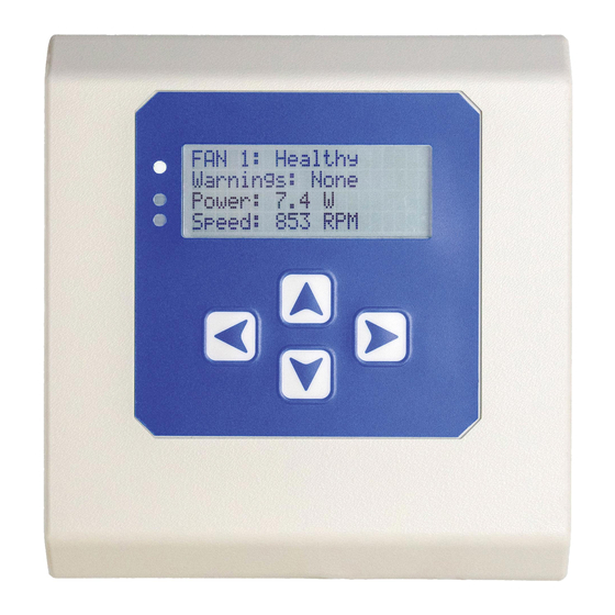
Modbus Display & Control (MDC)
Brand:
Ebmpapst
| Category:
Controller
| Size: 2.43 MB
Table of Contents
Table of Contents
2
1 Safety Notice
5
2 Introduction
6
Table 1 - Information Shown on the MDC Display for a Single Fan
6
Table 2 - Information Shown on the MDC Display for the Fan Array
6
3 Overview
7
Specification
7
Installation
7
Hot Plugging
7
RS485 Wiring Installation
7
Figure 1 - Schematic of RS485 Installation
7
Table 3 - Specification
7
4 Configuration and First Use of the MDC
8
Electrical Connection - General Information
8
General and Initial Power on
8
Figure 2 - Typical Wiring for Default Operating Mode When Used with Multiple Fans
8
Figure 3 - Fan Status Screen Showing that the MDC Had a Previously Stored Fan Array
8
Configuring the Fan Array
9
Configuring the MDC with Fans that Are in Their Factory Default Setting
9
Figure 4 - Keypad Buttons
9
Figure 5 - Main Menu Display Screen on First Application of Power
9
Auto Addressing Fans Using the Fan's Serial Numbers
10
Configuring the MDC with Fans that Have Been Pre-Configured
10
Fan Status Screen
11
Figure 6 - Fan Status Screen
11
Power Meter Screen
12
Changing the Fan Addressing Order
12
Figure 7 - Power Meter Screen
12
5 Operating Modes
13
General
13
Accessing the Main Menu
13
Monitor Mode (Default Operation)
13
Monitor Mode: Single Fan Connection
14
Monitor Mode: Multiple Fan Connection
14
Figure 8 - Typical Wiring Diagram for Monitor Operating Mode - Single Fan Monitoring
14
Figure 9 - Typical Wiring Diagram for Monitor Operating Mode - Multiple Fan Monitoring
14
Monitor Mode: Pressure Sensor Connection - Differential Pressure or Volume Measurement
15
Monitor & Control Mode
15
General
15
Measuring the Fan Performance Using a Pressure Sensor
15
Figure 10 - Typical Wiring Diagram for Monitor Operating Mode - Using External Sensor Monitoring
15
Control Options in Monitor & Control Mode
16
0-10V Input Control Option Using a Potentiometer and 10VDC Supply from the Fans
16
Figure 11 - Typical Wiring Diagram for Monitor & Control Operating Mode - Potentiometer Control Signal and Fan 10VDC Supply
16
0-10V Input Control Option Using Potentiometer and the On-Board 10VDC Supply
17
0-10V Input Control Option Using an External 0-10V Supply
17
Modbus Control Option
17
Figure 12 - Typical Wiring Diagram for Monitor & Control Operating Mode - Potentiometer Control Signal and on
17
Board 10VDC Supply
17
Figure 13 - Typical Wiring Diagram for Monitor & Control Operating Mode - External 0-10V Control Signal
17
Figure 14 - Typical Wiring Diagram for Monitor & Control Operating Mode - Modbus RS485 Control Signal
17
Differential Pressure or Volume Flow Measurement When Using Modbus And/Or Keypad Control Options
18
Figure 15 - Typical Wiring Diagram for Monitor & Control Operating Mode - Keypad Control Signal
18
Figure 16 - Typical Wiring Diagram for Monitor & Control Operating Mode - Using External Sensor Monitoring
18
Keypad Control Option
18
Constant Volume/Constant Pressure Operating Mode
19
General
19
Constant Volume/Constant Pressure Mode
19
Figure 17 - Typical Wiring Diagram for Constant Volume / Constant Pressure Operating Mode
19
Figure 18 - Mdcs Operating as Modbus Relays Connected to a BMS Network and Sub-Network of Fans
20
Modbus Relay Operating Mode
20
Advanced Settings Submenu
21
Ebm-Papst UK Ltd
21
Fan Replacement
23
6 Fault Indication
23
Loss of Communication and Fan Alarms
23
Figure 19 - Communication Lost Figure 20 - Fan Alarm
23
Warning Indications
24
7 Replacing a MDC Unit
24
8 Transport & Storage
24
9 Maintenance and Servicing
24
Figure 21 - Example of a First Warning on a Fan Figure 22 - Example of a Second Warning on a Fan
24
10 Copy of CE Certificate Front Sheet
25
Appendix A - Physical Details
26
Appendix B - Electrical Connections
27
Figure 23 - PCB Connections
27
Table 4 - PCB Bottom Side Connector Identities and Pin Functions
27
Table 5 - PCB Top Side Connector and Pin Function
27
Appendix C - Remote Monitoring & Control
28
Remote Monitoring
28
Remote Fan Array Control
28
Remote Single Fan Speed Control
28
Appendix D - Modbus Input Registers
29
Table 6 - Modbus Input Registers
29
Appendix E - Modbus Holding Registers
30
Table 7 - Controller's Dedicated Modbus Holding Registers Part 1
30
Table 8 - Controller's Dedicated Modbus Holding Registers Part 2
31
Table 9 - Direct Access to Individual Fan Holding Registers
31
Appendix F - Alarms and Warnings Holding Registers Breakdown
36
Table 10 - Alarms Registers Breakdown
36
Table 11 - Warning Registers Breakdown
36
Appendix G - Example of Modbus Relay Operation
37
Appendix H - Menu Structure Flow Chart
38
H1 - Fan Addressing - New Fan Array -Initial Setup
38
H2 - Fan Addressing - Existing Fan Array - Initial Setup
38
H3 - Initial Factory Reset
38
H4 - Fan Replacement
38
H5 - Main Menu
38
H6 - Status
39
H7 - Operation Mode - Monitor
39
H8 - Operation Mode - Monitor & Control
40
H9 - Operation Mode - Constant Volume / Constant Pressure
40
H10 - Operation Mode - Modbus Relay
40
H11 - Keypad Control
40
H12 - Operation Mode - Constant Volume / Constant Pressure Details
41
H13 - Advanced Settings - RPM Limit
41
H14 - Advanced Settings - 0-10V Control Cap
42
H15 - Advanced Settings - 0-10V Input Cap
42
H16 - Advanced Settings - Alarm Output (Sensor Disabled)
42
H17 - Advanced Settings - Alarm Output (Sensor Enabled)
42
H18 - Advanced Settings - BMS Settings
43
H19 - Advanced Settings - Main Menu Lock
43
H20 - Advanced Settings - LCD Brightness
44
H21 - Advanced Settings - Factory Reset
44
210-OMI14229-Iss2 Operation & Maintenance Instructions
45
H22 - Advanced Settings - Measurement Unit
45
H23 - Advanced Settings - PID Settings
45
Advertisement
Advertisement
Related Products
Ebmpapst Categories
Fan
Engine
Motherboard
Gateway
Controller
More Ebmpapst Manuals
Login
Sign In
OR
Sign in with Facebook
Sign in with Google
Upload manual
Upload from disk
Upload from URL