Sign In
Upload
Manuals
Brands
Dynon Avionics Manuals
GPS
SkyView Classic
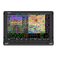
Dynon Avionics SkyView Classic Manuals
Manuals and User Guides for Dynon Avionics SkyView Classic. We have
1
Dynon Avionics SkyView Classic manual available for free PDF download: System Installation Manual
Dynon Avionics SkyView Classic System Installation Manual (573 pages)
Brand:
Dynon Avionics
| Category:
GPS
| Size: 17 MB
Table of Contents
Contact Information
3
Copyright
3
Limited Warranty
4
Changes in this Revision
5
Table of Contents
7
1 Introduction
15
Warning
16
Dynon Avionics Product Registration
16
About this Guide
17
Semantics of "Software" Vs "Software
18
Skyview Classic, Skyview Touch, Skyview SE, and Skyview HDX
18
Special Light Sport Aircraft (S-LSA) Considerations with Skyview
18
Getting Started
19
2 System Planning
23
Skyview Units Cannot / Should Not be Mixed
23
9-Pin D9F and D9M Connectors Are Skyview Network (Not RS-232 Serial)
24
Skyview Network Is a "Party Line
24
External Switches and Indicators
25
Skyview Display Resolution
25
Skyview System Maximum Number of Displays
25
Power Specifications
26
Major Unit Physical Specifications
28
Temperature Specifications
29
General System Installation Tips
30
Skyview System Can be on During Engine Start
30
Installing Skyview in an IFR-Equipped Aircraft
30
Mounting Requirements
31
Skyview System Construction
31
Example Skyview Systems
35
HSI Requirements
39
3 Basic Skyview Display Operation
41
Screen Synchronization
41
Display Bezel Layout
42
Joystick and Button Operation
43
Skyview Touch - Touch Interface Features Not Used in Setup Menus
45
Menu Navigation
46
Basic Display Operation Procedures
47
In Flight Setup Menu
49
Setup Menu
50
SYSTEM EVENT Menu
50
SYSTEM SOFTWARE Menu
51
SYSTEM SETUP Menu
52
LOCAL DISPLAY SETUP Menu
53
PFD SETUP Menu
54
EMS SETUP Menu
55
MAP SETUP Menu
55
AUTOPILOT SETUP Menu
56
TRANSPONDER SETUP Menu
56
HARDWARE CALIBRATION Menu
56
Software Updates and File Operations
57
How to Update Software
58
How to Export System Settings
59
How to Load and Delete Files
59
How to Export Data Logs and Waypoints
59
4 Skyview Display Installation and Configuration
61
Location Requirements for Skyview Displays
62
Electrical Installation
77
Power Input
77
Grounding
77
Airplane Master Contactor / Relay Considerations
77
SV-BAT-320 Connection and Operation Rules
77
Skyview Network Connectors
78
Network Setup and Status
78
Ethernet Connection
81
Internal Time Keeping
81
RS-232 Serial Devices
81
USB Usage and Accessibility
92
External DIM Control (Dimming) Connections
93
Contact Inputs
95
Reserved Connections for Future Use
95
Display Setup
96
How to Access Display Hardware Information
96
Serial Port Configuration
96
Brightness Setup
98
Top Bar Setup
99
Aircraft Information
99
Skyview Classic, Skyview SE Screen Layout Setup
100
Skyview HDX Display Setup / Layout
101
Skyview Classic and Skyview HDX Touch Setup
102
Glide Ring Setup
102
Weight and Balance Setup
102
Maintenance Log Setup
103
5 SV-ADAHRS-200/201 Installation and Configuration
105
Optional Components for Easier Installation of Your SV-ADAHRS-200/201
107
Physical Installation
108
SV-ADAHRS-200/201 Location Requirements
108
Skyview Network Connection
116
Pneumatic Ports
116
Compass Calibration
117
On-Ground Compass Calibration Procedure
118
In-Flight Compass Calibration Procedure
119
SV-OAT-340 Location and Installation
121
PFD-Related Settings
123
Other ADAHRS Calibrations
125
Performing Pitot/Static Checks
126
6 SV-MAP-270 Navigation Mapping License Purchase and Setup
129
License Information
129
Databases
131
Viewing Information about Installed Databases
131
Terrain Database
134
Aviation/Obstacle Databases
135
US Skyview Pilots - Stadium TFR Database
136
Charts and Airport Diagrams
137
Loading Databases
138
Removing Databases
138
7 SV-EMS-220/221 Installation and Configuration
141
Physical Installation
143
Skyview Network Connection
145
Skyview EMS Sensor Definition and Configuration Files
145
Engine Sensor and Transducer Planning
145
Example Engine Sensor and Transducer Installations
160
Lycoming/Continental 4-Cylinder Carbureted
161
Lycoming/Continental 4-Cylinder Fuel Injected
163
Lycoming/Continental 6-Cylinder Carbureted
165
Lycoming/Continental 6-Cylinder Fuel Injected
167
Jabiru 2200
169
Jabiru 3300
171
Rotax 912 ULS Carbureted
173
Rotax 912 Is (Electronic Control Unit)
175
Dual Engine Support Using Dual SV-EMS-220/221S and Two Skyview Classic Displays
182
Engine Sensor and Transducer Installation
183
Engine Sensor Accuracy and Grounding
183
Tools and Equipment Required
184
Voltmeter Inputs
184
Exhaust Gas Temperature (EGT) Sensors
184
Cylinder Head Temperature (CHT) Sensors
186
Tachometer
187
Manifold Pressure Sensor
189
Oil Pressure Sensor
190
Oil Temperature Sensors
193
Fuel Pressure Sensor
194
Fuel Flow Transducer
197
Fuel Level Sensor
199
Ammeter Shunt
201
Carburetor Temperature Sensor
205
Rotax CHT Sensors
205
Trim and Flaps Position Potentiometers
206
Coolant Pressure Sensor
207
Coolant Temperature Sensor
209
General Purpose Temperature Sensor
209
Rotax 914 Air Box Temperature
210
Contacts
210
General Purpose Thermocouple
211
External EMS Warning Light
212
Engine Information
212
EMS Sensor Definitions, Mapping, and Settings
214
EMS Sensor Definitions
214
EMS Sensor Input Mapping
215
EMS Sensor Settings
216
EMS Screen Layout Editor
225
EMS Sensor Calibration
227
Skyview HDX ENGINE BOTTOM BAND
228
8 SV-GPS-250/2020 GPS Receiver Installation and Configuration
229
WAAS Data Reception
230
Use of the SV-GPS-2020 Outside the US
231
Considerations for Converting an SV-GPS-250 to an SV-GPS-2020 in Special Light Sport Aircraft (S-Lsas)
231
Physical Installation
232
Considerations for Installing an SV-GPS-2020 in an Aircraft with an Installed SV-GPS-250
234
Serial Data Connection
235
Configuration - SV-GPS-2020 Only, Serial Port 5
238
Configuration - SV-GPS-2020 (Serial Port 5) and SV-GPS-250 (Serial Port 4)
238
Testing / Troubleshooting Installation of the SV-GPS-250 And/Or SV-GPS-2020
239
Part 1 - Basic Serial Port Functionality
239
Part 2 - GPS Receive Performance
240
(US Only) Additional Configuration Required for SDA/SIL=1
243
Additional Configuration Required for Compliance with FAA 2020 ADS-B out Mandate
243
9 SV-BAT-320 Backup Battery Installation
245
Physical Installation
246
SV-BAT-320 Location
246
Electrical Connection
247
Charging the SV-BAT-320
247
SV-BAT-320 Is Automatically Charged in Flight
248
Charging the SV-BAT-320 on Ground or During Aircraft Construction
248
Battery Status Icon
249
Detailed Battery Status Check
249
Initial SV-BAT-320 Test
250
In the Event of Initial SV-BAT-320 Test Failure
251
SV-BAT-320 Specifications
252
Returning an SV-BAT-320 to Dynon Avionics for Exchange (Warranty Replacement)
252
10 AP Servo Installation, Configuration, and Calibration
255
Dynon Avionics Autopilot Servo Models
257
Compass Calibration Requirement
257
Additional Resources
257
Servo Mechanical Installation
258
Autopilot Servo Calibration and Test Procedures
270
Autopilot Servo Initial Setup
271
Autopilot In-Flight Tuning Procedures
277
11 SV-XPNDR-261/262 Installation and Configuration
279
Physical Installation
281
Electrical Connections
283
Antenna Installation
290
Transponder-Related Skyview Display Settings
294
(US Only) Configuration Required for SDA/SIL=1 for Continued Reception of ADS-B Traffic (Early 2016)
301
Skyview Systems with an SV-GPS-250 as Primary GPS
302
(US-Only) Equipping for Compliance with FAA 2020 ADS-B out Mandate
303
Installation of Dynon Avionics SV-GPS-2020 for Compliance with FAA 2020 ADS-B out Mandate
305
SV-XPNDR-261/262 Software Updates
308
SV-XPNDR-261/262 Software Update SW02.09
313
SV-XPNDR-261/262 Software Update SW02.09 Quick Decision Points
313
Deprecated SV-XPNDR-261/262 Software Update Instructions and Notes
315
Skyview Software V12.2 - V13.0.3 SV-XPNDR-261/262 Software SW02.06 Update
316
SV-XPNDR-261/262 Software Version (SW) V2.02/V2.04/V2.06 Labeling Requirements (US Registered / Operated Aircraft Only)
317
Skyview Software V14.0 - V14.1 SV-XPNDR-261/262 Software Update SW02.08
318
SV-XPNDR-261/262 Software Update SW02.08 Quick Decision Points
318
SV-XPNDR-261/262 Post Installation Checks
319
Transponder Warnings (Transponder Self Diagnostics)
320
Performing Transponder Checks
321
Dynon Avionics SV-GPS-250 and SV-GPS-2020 Compliance Statements
322
12 SV-ARINC-429 Installation and Configuration
323
Physical Installation
323
Skyview Network Connection
324
ARINC-429 Device Connection
324
SV-ARINC-429 Related Settings
333
13 Vertical Power VP-X Integration and Configuration
335
VP-X Physical, Electrical Installation and Configuration
335
Serial Port Connection
336
License Information
337
VP-X Skyview Classic Display Settings
338
Post Installation Checks
339
14 SV-ADSB-470 Installation and Configuration
341
Physical Installation
342
Installation Instructions
343
Electrical Installation
344
Antenna Selection and Installation
347
SV-ADSB-470-Related Skyview Display Settings
349
Post Installation Checks
350
15 Accessory Installation and Configuration
353
Skyview System Angle of Attack Pitot Probe
353
Encoder Serial-To-Gray Code Converter
357
Capacitance to Voltage Converter for Van's Capacitive Plates
360
Skyview Video Input Adapter
361
Skyview Wi-Fi Adapter
365
Advanced Flight Systems (AFS) ADVANCED Control Module (ACM)
368
Sv-Button-Level
369
Pitot/Static/Aoa Pneumatic Installation Kit
373
Recommended Tools & Installation Accessories
376
Installation
376
Panel Module Faceplate Blank
379
Sv-Knob-Dimmer
380
16 SV-COM-C25 Installation and Configuration
383
Physical Installation: SV-COM-PANEL
384
Electrical Installation
388
Power Input
388
Audio Signal Grounding
388
Audio Shielding
388
Skyview Network Connectors
388
Electrical Connections
388
Antenna Installation
397
Skyview System Settings for SV-COM-C25
399
Post Installation Checks
401
Continued Airworthiness and Maintenance
402
17 SV-COM-X83 Installation and Configuration
403
Certification Considerations
404
Physical Installation: SV-COM-PANEL
404
Physical Installation: SV-COM-T8
406
Electrical Installation
409
Power Input
409
Audio Signal Grounding
409
Audio Shielding
409
Skyview Network Connectors
409
Electrical Connections
410
Antenna Installation
418
Skyview System Settings for SV-COM-X83
421
Post Installation Checks
422
Continued Airworthiness and Maintenance
422
18 SV-AP-PANEL Installation and Configuration
425
Physical Installation
427
Electrical Installation
428
Autopilot Auto-Trim
433
Post Installation Checks
433
19 SV-KNOB-PANEL Installation
435
Physical Installation
436
Electrical Installation
437
Post Installation Checks
437
20 SV-MAG-236 Installation and Configuration
439
Physical Installation
440
Optional SV-OAT-340 Connected to SV-MAG-236
442
Skyview Network Connection
445
Compass Calibration
445
On-Ground Compass Calibration Procedure
446
In-Flight Compass Calibration Procedure
447
Restoring Use of the SV-ADAHRS-200/201 Internal Magnetometer
449
21 Appendix A: Maintenance and Troubleshooting
451
Cleaning a Skyview Display
451
Saving a Screenshot of a Specific Screen
452
Savings a Settings File (Configuration of Your Skyview System)
452
Saving a Dynon Diagnostic File
452
Skyview Displays Error: SYS EVENT 5: SEE SETUP
453
Returning Skyview Components to Service after Repair
453
In a Multi-Display Skyview System, Continuing to Fly with a Missing Display
456
Operational Status
457
Instructions for Continued Airworthiness
459
Annual SV-BAT-320 Test
460
Troubleshooting
462
22 Appendix B: Specifications
467
Skyview / Dynon Avionics Minor Equipment Weights
467
Skyview Compatible Engine Sensors (Sold by Dynon Avionics)
468
SV-BAT-320 Specifications
469
SV-XPNDR-261 Specifications
470
SV-XPNDR-262 Specifications
471
SV-XPNDR-261/262 ADS-B Information
474
SV-COM-C25 Technical Specifications
476
SV-COM-X83 (TY91L VHF Radio Unit) Technical Specifications
477
SV-GPS-250 Specifications
478
SV-GPS-2020 Specifications
479
23 Appendix C: Wiring and Electrical Connections
481
Wire Gauge
481
Grounding
481
DSUB Crimp Contacts and Tools
482
Non-Dynon Avionics Wire Harness Considerations
482
Skyview Equipment Electrical Connections
484
Skyview Equipment Electrical Connector Pinout Tables
486
Servo Pinout (SV-NET-SERVO)
486
Skyview Display D37 Pinout (SV-HARNESS-D37)
487
Skyview D37M Block Diagram
488
SV-EMS-220/221 Pinouts (EMS Harnesses)
491
SV-ARINC-429 Pinout
494
SV-XPNDR-261/262 Pinout (SV-HARNESS-XPNDR)
496
SV-AP-PANEL Pinout (D15M Connector)
498
SV-COM-PANEL Pinout (D15M)
499
SV-COM-425 Pinout
500
SV-COM-T8 Pinout
502
24 Appendix D: SV-EMS-220/221 Sensor Input Mapping Worksheet
505
25 Appendix E: Serial Data Output
507
DYNON ADAHRS Serial Data Format
508
DYNON SYSTEM Serial Data Format
510
DYNON EMS Serial Data Format
513
DYNON ADAHRS / SYSTEM / EMS Serial Data Output Combinations
517
NMEA out Serial Data Formats
518
26 Appendix F: User Data Logs
521
User Data Log
521
Recent Flight Data Log
522
Alert Data Log
522
History Data Log
523
Data Logging Recording Options
523
Exporting Data Logs
523
27 Appendix G: Kavlico Pressure Sensor Part Numbers
525
Dynon Avionics Technical Advisory 120214 - Kavlico Pressure Sensors
525
28 Appendix H: Sensor Debug Data
527
29 Appendix I: Skyview System Installation Guide Revision History
531
30 Appendix J: Checklists
561
Saving Your Checklist with "UTF-8 Character Encoding
562
Example Checklist
564
Example Checklist Formatting Notes
565
Excel Checklist Generation Tool
566
Loading a Checklist
566
Displaying Your Checklist on Your Skyview Display
569
31 Appendix K: Switches, Etc. External to Skyview Units
571
Advertisement
Advertisement
Related Products
Dynon Avionics SkyView SE
Dynon Avionics SkyView Touch
Dynon Avionics SkyView HDX
Dynon Avionics SkyView
Dynon Avionics SkyView HDX Series
Dynon Avionics SV-INTERCOM-2S
Dynon Avionics SkyView SV-D700
Dynon Avionics SkyView SV-D1000
Dynon Avionics EFIS-D100
Dynon Avionics EMS-D10
Dynon Avionics Categories
Avionics Display
GPS
Autopilot System
Intercom System
Transceiver
More Dynon Avionics Manuals
Login
Sign In
OR
Sign in with Facebook
Sign in with Google
Upload manual
Upload from disk
Upload from URL