Sign In
Upload
Manuals
Brands
Dynamatic Manuals
Controller
EC 2000
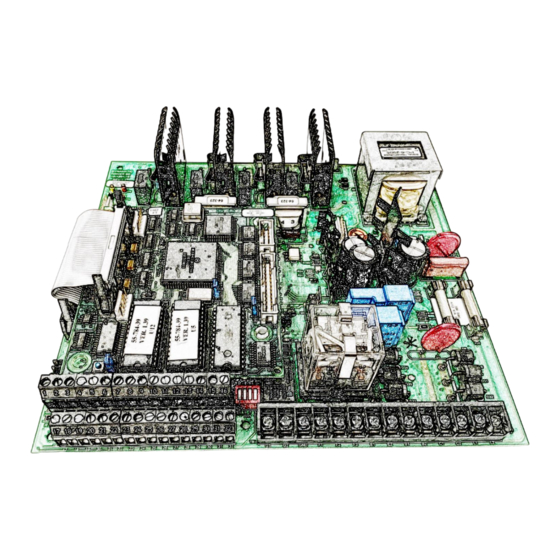
User Manuals: Dynamatic EC 2000 Current Drive
Manuals and User Guides for Dynamatic EC 2000 Current Drive. We have
2
Dynamatic EC 2000 Current Drive manuals available for free PDF download: Instruction Manual
Dynamatic EC 2000 Instruction Manual (55 pages)
Brand:
Dynamatic
| Category:
Computer Hardware
| Size: 3 MB
Table of Contents
Table of Contents
2
Section 1 - Theory of Operation
5
Figure 1: Eddy Current Drive & Control Block Diagram
5
Figure 2: EC 2000 Keypad Display
6
Section 2 - Specifications
7
Features
7
Power and Load Ratings
7
Electrical Protection
7
Environmental Ratings
8
Electrical Noise
8
Enclosures
8
Weight
8
Dimensions
8
Reliability
8
Codes and Standards
8
Section 3 - Control Operation Modes
9
Control Modes
9
Other Modes of Operation
9
SECTION 4 - Inputs/Outputs
10
Analog Inputs
10
Digital Inputs
10
Analog Outputs
10
Digital Outputs
11
Section 5 - Installation
12
Figure 3: Standard Panel Dimensions
12
Figure 4: Keypad Cutout Template
13
Figure 5: Keypad Dimensions
14
Mounting Hardware
15
Figure 6: Standard NEMA Rated Enclosure Dimensions
15
Wiring
16
Figure 7: "TB1" Terminal Block Includes Tachometer Wiring
16
Figure 8: Start/Stop/Jog & E-STOP Wiring
17
Figure 9: Set Point Reference & Manual/Auto Mode Wiring
17
Figure 10: Programmable Analog Outputs Wiring
18
Figure 11: Current Transformer Wiring for Torque Limiting
18
Figure 12: Preset Speeds and PLC Run Wiring
19
Figure 13: Tach Speed Pulse Pickup Wiring
19
Figure 14: Process Feedback Wiring
20
Figure 15: Relay 1-4 Connection Diagram
20
Figure 16: Tachometer Follower and Pulse Pickup Follower Wiring
20
Hardware Setup
22
Table 1: EC 2000 Jumper Settings
22
Table 2: Follower Setpoint Jumper Settings
22
Table 3:Torque Limiting SW1 Settings
22
Section 6 - Keypad
23
Table 4: Keypad Button Descriptions
23
Section 7 - Programming
24
Menu A: Control Setup
24
Table 5: Mechanical Unit Tach Pulses/Rev Setting
25
Menu B: Clutch Performance
29
Torque Limit
30
Menu C: Acceleration/Deceleration Setup
30
Menu D: Brake Performance
31
Menu E: Follower Setup
33
Menu F: Analog Outputs
33
Menu G: Relay Output
35
Menu H: Units
36
User Units
36
Menu I: Potentiometer Setup
37
Menu J: Torque Potentiometer Setup
37
Menu K: Source Select
38
Menu L: Process
40
Menu M:torque Process
40
Menu N:external Process
41
Menu O FAULT
42
Menu P: Fault Timer Setup
42
Menu Q: Meter Select
45
Menu R: Serial Options
46
Menu N: Auto Restart
47
Section 8- Troubleshooting
49
Control will Not "Run" or "Start
49
No Output
49
Drive Runs at Full Speed
49
Fuses Blow
50
Cannot Change any Settings
50
Follower or Potentiometer Signal Not Changing Setpoint
50
Unstable Speed
50
Speed on Display Is Different than Actual Speed
50
Screen Is Frozen And/Or Has Unfamiliar Content
50
Screen Is Lit, but Nothing Is Displayed
50
Local/Remote Key Does Not Work
50
Drive Slower than Desired
51
Section 9 - Serial Communications
52
Data Transceiving Organization
52
Read and Write Requests
52
Notes
52
Data Acquisition
53
Table 6: Serial Data Acquisition
53
Section 10 - Index
54
Advertisement
Dynamatic EC 2000 Instruction Manual (46 pages)
Brand:
Dynamatic
| Category:
Controller
| Size: 2 MB
Table of Contents
Table of Contents
2
Figure 1: Eddy Current Drive & Control Block Diagram
5
Section 1 - THEORY of OPERATION
5
Figure 2: EC 2000 Keypad Display
6
Section 2 - SPECIFICATIONS
7
Features
7
Power and Load Ratings
7
Electrical Protection
7
Environmental Ratings
8
Electrical Noise
8
Enclosures
8
Weight
8
Dimensions
8
Reliability
8
Codes and Standards
8
Section 3 - CONTROL OPERATION MODES
9
Control Modes
9
Other Modes of Operation
9
Section 4 - INPUTS/OUTPUTS
10
Analog Inputs
10
Digital Inputs
10
Analog Outputs
10
Digital Outputs
11
Figure 3: Standard Panel Dimensions
12
Section 5 - INSTALLATION
12
Figure 4: Keypad Cutout Template
13
Figure 5: Keypad Dimensions
14
Figure 6: Standard NEMA Rated Enclosure Dimensions
15
Figure 7: "TB1" Terminal Block
16
Wiring
16
Mounting Hardware
15
Figure 9: Setpoint Reference & Manual/Auto Mode Wiring
17
Figure 8: Start/Stop/Jog & E-STOP Wiring
17
Figure 7: “TB1” Terminal Block
17
Figure 10: Programmable Analog Outputs Wiring
18
Figure 11: Current Transformer Wiring for Torque Limiting
18
Figure 12: Preset Speeds and PLC Run Wiring
19
Figure 13: Speed Pickup Wiring
19
Hardware Setup
20
Figure 14: Relay 1-4 Connection Diagram
20
Table 1: EC 2000 Jumper Settings
20
Table 2: Follower Setpoint Jumper Settings
21
Table 3:Torque Limiting SW1 Settings
21
Table 4: Keypad Button Descriptions
22
Section 6 - KEYPAD
22
Table 5: Mechanical Unit Tach Pulses/Rev Setting
23
Menu B: Clch Performance
28
Menu C: Accel/Decel Setup
29
Menu D: Brake Performance
29
Menu E: Follower Setup
30
Menu F: Analog Outputs
31
Menu G: Relay Output
32
Menu H: Units
33
Menu J: Potentiomtr Setup
34
Menu K: Source Select
34
Menu L: Process
36
Menu M: Fault
36
Menu N: Auto Restart
39
Section 7 - PROGRAMMING
23
Menu A: Control Setup
23
Section 8- Troubleshooting
40
Control will Not "Run" or "Start
40
No Output
40
Drive Runs at Full Speed
40
Fuses Blow
40
Cannot Change any Settings
40
Follower or Potentiometer Signal Not Changing Setpoint
41
Unstable Speed
41
Speed on Display Is Different than Actual Speed
41
Screen Is Frozen And/Or Has Unfamiliar Content
41
Screen Is Lit, but Nothing Is Displayed
41
Local/Remote Key Does Not Work
41
Drive Slower than Desired
41
Section 9 - ETHERNET IP and SERIAL COMMUNICATIONS
42
Data Transceiving Organization
42
Read and Write Requests
42
Notes
42
Data Acquisition
43
Table 6: Ethernet Ip/Serial Data Acquisition
43
Section 10 - INDEX
44
Advertisement
Related Products
Dynamatic 015-000248-2002
Dynamatic 015-000248-2003
Dynamatic 015-000248-2004
Dynamatic 15-533-1015
Dynamatic 15-539-0015
Dynamatic 15-539-14
Dynamatic 15-551-1015
Dynamatic 15-553-0015
Dynamatic 4000
Dynamatic 4050
Dynamatic Categories
Controller
Computer Hardware
Wheelchair
DC Drives
More Dynamatic Manuals
Login
Sign In
OR
Sign in with Facebook
Sign in with Google
Upload manual
Upload from disk
Upload from URL