Sign In
Upload
Manuals
Brands
DIEBOLD NIXDORF Manuals
Touch terminals
DN Series
DIEBOLD NIXDORF DN Series Manuals
Manuals and User Guides for DIEBOLD NIXDORF DN Series. We have
5
DIEBOLD NIXDORF DN Series manuals available for free PDF download: Installation Manual, Operator's Manual, Operating Manual
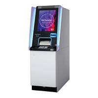
DIEBOLD NIXDORF DN Series Installation Manual (98 pages)
Brand:
DIEBOLD NIXDORF
| Category:
Touch terminals
| Size: 5 MB
Table of Contents
Table of Contents
2
1 Introduction
6
Symbols Used in this Manual
6
Section-Specific Warning Notes
7
2 Safety
8
Characters, Labels and Symbols
8
General Safety Precautions for the System
9
Notes Concerning Installation
12
3 Planning the Installation
13
System Dimensions
13
Frontload UL Safe 4H
13
Illustration 3-1 System Dimensions - Frontload UL Safe 4H
13
Frontload UL Safe 5H
14
Illustration 3-2 System Dimensions - Frontload UL Safe 5H
14
Frontload CEN Safe
15
Illustration 3-3 System Dimensions - Frontload CEN Safe
15
Overview of Installation Types
16
Dimensions of Cable Lead-Ins into the Safe
16
Frontload UL Safe
16
Illustration 3-4 Dimensions of Cable Lead-Ins for Frontload UL Safe
16
Frontload CEN Safe
17
Illustration 3-5 Rear Cable Lead-In - Frontload CEN Safe
17
Installation Options of System Versions
18
Perspective View UL Safe 4H (Free-Standing)
18
Illustration 3-6 Frontload UL Safe 4H
18
Perspective View UL Safe 5H (Free-Standing)
19
Illustration 3-7 Frontload UL Safe 5H
19
Perspective View CEN Safe (Free-Standing)
20
Illustration 3-8 Frontload CEN Safe
20
Position of Safe
21
Illustration 3-9 Position of UL Safe
21
Illustration 3-10 Position of CEN Safe
22
Ventilation Opening
23
Illustration 3-11 Ventilation Openings
23
Storage if Construction Work Is Not yet Complete
24
Space Required for Operation and Maintenance
25
Frontload Version with UL Safe
25
Illustration 3-12 Space Required for Operation and Maintenance, Frontload System with UL Safe
25
Frontload Version with CEN Safe
26
Illustration 3-13 Space Required for Operating and Maintenance, Frontload System with CEN Safe
26
Floor Space Requirements
27
Load-Carrying Capacity
27
Notes on Floor Mounting
27
Tear-Off Resistance in Compliance with Vds and en 1143-1 Guidelines
28
Mounting Without Installation Frames
29
General Information
29
Dimensions of the Safe Attachment Points
30
Illustration 3-14 Dimensions of Safe Attachment Points for Frontload UL Safe
30
Illustration 3-15 Dimensions of Safe Attachment Points for Frontload CEN Safe
31
Dimensions of Cable Lead-Ins
32
Illustration 3-16 Dimensions of Cable Lead-Ins for Frontload UL Safe
32
Illustration 3-17 Dimensions of Cable Lead-Ins for Frontload CEN Safe
33
Tear-Off Sensor
34
Drilling Diagrams
35
Drilling Diagram: Frontload UL Safe
35
Illustration 3-18 Drilling Template for Device with UL Safe (Frontload)
35
Drilling Diagram: Frontload CEN Safe
36
Illustration 3-19 Drilling Template for (Frontload) Device with CEN Safe
36
Network and Data Cables
37
Power Supply
38
Remote Status Indicator
39
Cable Lead-Ins into in the Safe
40
Rear Cable Lead-In - Frontload
40
Illustration 3-20 Cable Lead-In into the Safe from the Rear
40
Transport Route Requirements
41
Transport Dimensions UL Safe Frontload
42
Illustration 3-21 Transport Dimensions of the Frontload Wooden Shipping Pallet, 4H UL Safe
42
Illustration 3-22 Transport Dimensions of the Frontload Wooden Shipping Pallet, 5H UL Safe
43
Illustration 3-23 Transport Dimensions of the Frontload Metal Shipping Bracket, 4H UL Safe
44
Illustration 3-24 Transport Dimensions of the Frontload Metal Shipping Bracket, 5H UL Safe
45
Illustration 3-25 Transport Dimensions of UL Safe Frontload
46
Illustration 3-26 Minimum Transport Dimensions UL Safe Frontload
47
Transport Dimensions CEN Safe Frontload
48
Illustration 3-27 Transport Dimensions of the Frontload Wooden Shipping Pallet, CEN Safe
48
Illustration 3-28 Transport Dimensions of the Frontload Metal Shipping Bracket, CEN Safe
49
Illustration 3-29 Transport Dimensions CEN Safe Frontload
50
Illustration 3-30 Minimum Transport Dimensions CEN Safe Frontload
51
4 Installation
52
Removing the Transport Packing
52
Disassembly of Wooden Shipping Pallet
53
Illustration 4-1 Wooden Shipping Pallet - Only Shift in the Directions Indicated
53
Illustration 4-2 Shipping Pallet - Removing Screws
54
Illustration 4-3 Shipping Pallet - Removing from the System
55
Disassembly of Metal Shipping Bracket
56
Illustration 4-4 Metal Shipping Bracket - Only Shift in the Directions Indicated
56
Illustration 4-5 Shipping Bracket - Removing Screws
57
Illustration 4-6 Shipping Bracket - Removing from the System
58
Removal of Shipping Restraints
59
TP30/TP31 Receipt Printer
61
Removal of AFD to Install Anchor Bolts
62
Mounting Sets
64
Mounting Sets (Optional)
64
Mounting Set (for UL Safe)
64
Mounting Set (for CEN Safe)
64
Mounting Set (Expansion Anchor Set)
64
Overview of Installation Types
65
Mounting the Device
66
Illustration 4-7 Mounting Structure Without Installation Frame
66
Illustration 4-8 Installation with Mounting Anchors-Marking out Bore Holes
67
Illustration 4-9 Installation with Mounting Anchors-Drilling Bore Holes
67
Illustration 4-10 Installation with Mounting Anchors-Aligning the System
68
Illustration 4-11 Installation with Mounting Anchors- Securing the System
68
Installation Without Frame
70
Putting into Service
70
Access the Relay Panel for External Features (Frontload)
71
Installing the 'Remote Status Indicator
72
Remote Status Indicator' - Standard
72
Remote Status Indicator' - Audio
77
Shortening Cable Ends
82
5 Appendix
88
Checklist for Installation Preparations
88
Technical Data
92
General Installation Conditions
92
Environmental Conditions
94
Compliance with Standards and Approvals
95
Environmental Protection
96
Advertisement
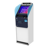
DIEBOLD NIXDORF DN Series Operator's Manual (91 pages)
Brand:
DIEBOLD NIXDORF
| Category:
Touch terminals
| Size: 5 MB
Table of Contents
Table of Contents
2
Introduction
7
Symbols Used in this Manual
8
Section-Specific Warning Notes
9
Signs, Markings and Symbols
10
Table 1-1 Warning Signs Used
10
Table 1-2 Mandatory Signs Used
10
Safety
11
General Safety Precautions for the System
11
Radio Interference
14
General Power Interruption
15
Figure 2-1 Switching off the System
15
Figure 2-2 General Power Interruption - Disconnecting the Plug
15
Description
16
System Overview
16
Overall View
16
Figure 3-1 Frontload Overall View - CEN Safe
16
Figure 3-2 Rearload Overall View - CEN Safe
17
Figure 3-3 Rear View with Operator Panel Inspection Window
18
Chassis Components
20
Figure 3-5 Fascia Open
20
Figure 3-6 Rear Door Opened - Without Operator Panel Inspection Window
21
Figure 3-7 Rear Door Opened with Operator Panel Inspection Window
22
Component Carrier Pulled out
23
Figure 3-8 Frontload Component Carrier with TP29/TP30
23
Figure 3-9 Frontload Component Carrier with TP29/TP31
24
Figure 3-10 Component Carrier Pulled out - Rearload
25
Cash Components
26
Fascia Components
28
Figure 3-13 15" Version, Broadside Format with Function Keys
29
Figure 3-14 15" Version, Broadside Format Without Function Keys
30
Figure 3-15 19" Version, Broadside Format Without Function Keys
31
Figure 3-16 19" Version, Portrait Format Without Function Keys
32
Figure 3-17 Version 15" with Function Keys - Rearload
34
Figure 3-18 Guide Lights
35
Figure 3-19 Keyboard Privacy Shield
36
Safe Components
37
Figure 3-20 Front Door Opened
37
External Control Unit
38
Figure 3-21 External Control Unit - Overview
38
Functions of the External Control Unit
39
Table 3-1 Functions of the On/Off Button
39
LED Codes
40
Card Box (Removable)
42
Figure 3-22 Removable Card Box
42
Card Box (Lockable)
43
Figure 3-23 Lockable Card Box
43
Remote Status Indicator
44
Technical Data
46
General Installation Conditions
46
Table 3-2 Electrical Characteristics of the Supply Network
46
Table 3-3 System Conditions
47
Environmental Conditions
49
Table 3-6 Climatic Environmental Conditions
49
Operation
50
Opening/Closing the Doors
50
Opening/Closing the Front Door
51
Figure 4-1 Opening the Rontload Front Door
51
Figure 4-2 Opening the Frontload Front Door
51
Figure 4-3 Closing the Frontload Front Door
52
Figure 4-4 Closing the Front Door with a Key
52
Opening/Closing the Rear Door
53
Figure 4-5 Opening the Rear Door
53
Opening/Closing the Fascia
54
Opening/Closing the Frontload Fascia
54
Figure 4-6 Opening the Fascia
54
Figure 4-7 Closing the Fascia
54
Opening/Closing the Rearload Fascia
55
Figure 4-8 Rearload System - Actuating the Release
55
Figure 4-9 Rearload System - Opening the Fascia
55
Opening/Closing the Fascia with Fascia Lock
56
Figure 4-10 Rearload - Closing the Fascia
56
Figure 4-11 Opening the Fascia Lock
56
Figure 4-12 Opening the Fascia with Fascia Lock
57
Figure 4-13 Closing the Fascia with Fascia Lock
57
Starting up / Shutting down the System
58
Starting up the System
58
Figure 4-14 Switching off the System
58
Shutting down the System
59
Starting T/SOP
59
Figure 4-15 Turning off the System
59
Figure 4-16 Calling the T/SOP
59
Pulling Out-Pushing in Components
60
Pulling out / Pushing in Cash Components
60
Component Carrier
63
Opening/Closing the Additional Latching Mechanism of the Upper Unit
65
Emptying the Card Box (Removable)
67
Removing the Card Box
67
Opening the Card Box
68
Closing the Card Box
70
Pushing in the Card Box
71
Emptying the Card Box (Lockable)
71
Opening the Card Box
71
Removing Cards
72
Closing the Card Box
73
Opening/Closing the Operator Panel
74
Opening/Closing the Operator Panel Inspection Window
74
Opening/Closing the Operator Panel
75
Replacing the Logo in the Fascia
76
Branding Label Fascia
76
Adhesive Branding Label
79
4.10 Setting the Volume of the Headphone Jack
80
Troubleshooting
81
General Information
81
Prerequisites for Troubleshooting
81
Prerequisites for Troubleshooting
82
Maintenance
83
Disposal
84
Corresponding Documentation
85
Table 8-1 Related Documentation
85
Appendix
86
Compliance with Standards and Approvals
86
Declaration of Conformity
88
Environmental Protection
89
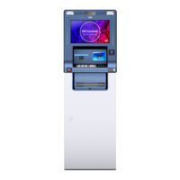
DIEBOLD NIXDORF DN Series Operator's Manual (71 pages)
Brand:
DIEBOLD NIXDORF
| Category:
Touch terminals
| Size: 3 MB
Table of Contents
Table of Contents
2
Introduction
4
Symbols Used in this Manual
4
Important Safety Precautions
4
Special Declaration
4
Special Notice
5
Warning Indication
5
Notices
6
Safety Indication
7
Device Overview
8
Device Type
8
DN Series K30/31 Overall View
8
Internal Layout
9
Explanatory Drawing of Moving Parts
12
Basic Operation
13
Basic Operation
14
Opening/Closing the Device Door
14
Lifting Up/Pushing down the Customer Panel Cover
15
Operations of Back Door
16
Rotate the Printer
16
Pulling Out/Pushing in the Device Carriage
17
Pulling Out/Pushing in the Pull-Out Paper Tray
18
Consumables Operating Instructions
18
Consumables of Statement Printer
18
Description of Status Light/Indicator Light
22
Printing Paper Status Indicator Light
22
Taking Paper out from the Reject bin
23
Switching the Device ON/OFF
24
Switching the Device on
25
Switching the Device off
26
Insert of Identification Card
27
Volume Adjustment Method
27
Reading 2D Barcode
28
Maintenance Keyboard Operating Instructions
29
Customer Connection Box
30
Functions of Customer Connection Box USB
30
Plug Description
30
Wiring Diagram
31
Example of User Feedback Information
31
Position of the Type Label
32
Forms Printer TP20
33
Function Elements and Controls TP20
34
Printer Control Panel
35
Key Functions
35
Replenishing the Paper Supply
35
Removing Paper
37
Messages on the Status Display Screen
37
Error Messages and Warnings
38
Malfunctions
41
Eliminating a Paper Jam in the Drum
42
Eliminating a Paper Jam in the Document Feed
44
Remedying Poor Print Quality/Paper Jams Caused by Marking Errors
46
Initiating a Test Print
48
Cleaning and Care
51
Paper Specifications
52
Card Reader CHD V2CU
54
Controls
55
Security Access Module (SAM)
57
Inserting the SAM Module
57
Removing an Arrested ID Card
59
Inserting an ID Card
61
Depositing Retained ID Cards
62
Cleaning
62
Cleaning Procedure
63
Troubleshooting
64
Manual Card Transport
64
5.10 Card Reject Box
65
Cleaning Method
66
Shell Cleaning
66
EPP - Keyboard Cleaning
66
Display Screen Cleaning
66
Document Scanner Cleaning
67
Consumables List
67
Appendix
68
Technical Data
68
General Installation Conditions
68
Approved Cleaning Materials
69
General Purpose Cleaning Materials
69
Cleaning Material for Special Components
69
Environmental Protection
70
Environmentally and Recycling-Friendly Product Development
70
Saving Energy
70
Disposing of Used Consumables
70
Labels on Plastic Case Parts
70
Returning, Recycling and Disposing of Used Units and Consumables
70
Advertisement
DIEBOLD NIXDORF DN Series Operating Manual (58 pages)
Brand:
DIEBOLD NIXDORF
| Category:
Cash Counter
| Size: 2 MB
Table of Contents
Table of Contents
2
Legal Disclaimer
5
Safety
6
Important Safety Precaution
6
Notes Concerning Installation
6
General Safety Precautions
6
Introduction
9
Symbols Used in this Manual
9
General Power Interruption
9
DN Series 100D FL
10
Device Overview
12
System Types
12
DN Series 100D Frontload
12
Controls
13
Frontload Overall View
13
Fascia
14
Component Carrier Pulled out
15
Fascia Opened
16
Front Door Opened
17
Safe Opened
18
General Information
22
Calling the Product-Specific Software
22
Frontload
23
Opening/Closing the System Doors
23
DN Series 100D Frontload
24
Opening/Closing the Safe Door
30
Opening/Closing the Safe Door (with Factory Setting)
30
Customizing the Key and Number Combination Locks
37
Opening/Closing the Safe Door (with Customized Lock)
42
Opening the Safe Door (with Customized Lock)
42
Closing the Safe Door (with Customized Lock)
46
Switching the System on
48
Frontload
49
Switching the System off
50
Frontload
51
Setting the Volume of the Headphone Jack
52
Remote Status Indicator
53
TP30/TP31 Receipt Printer
55
Servicing the TP30/TP31 Receipt Printer
55
TP29 Journal Printer
55
Problems
56
General Information
56
DIEBOLD NIXDORF DN Series Operator's Manual (25 pages)
Check Deposit Module
Brand:
DIEBOLD NIXDORF
| Category:
Control Unit
| Size: 1 MB
Table of Contents
Table of Contents
3
Introduction
4
Figure 1-1 DN ™Series Check Deposit Module (bin Side)
4
Information in this Manual
5
Safety Precautions
5
Figure 1-2 DN Series™ Check Deposit Module (PBCA Side)
5
Signs, Labels and Symbols
7
Table 1-1 Warning Signs Used
7
Table 1-2 Used Mandatory Signs
7
General Safety Instructions for the Component
8
Maintenance
9
Prerequisite Information
9
Maintenance Procedures
9
Table 3-1 Dimensions of the Document
9
Table 3-2 bin Capacity
9
Table 3-3 Recognized Fonts
9
Checking the Print Quality
10
Clearing a Jam
12
Figure 3-2 Green Tab for the Exception bin
13
Figure 3-4 Open the Escrow Turn
15
Figure 3-6 Positions of the Escrow Assembly Kickstand
18
Figure 3-7 Center and Deskew (CDS) Assembly Raised
19
Figure 3-8 Empty Escrow Roll Button
20
Inkjet Printer Cartridge
21
Figure 3-9 Inkjet Printer Cartridge
21
Beep Codes for Error Conditions
23
Table 3-4 Beep Codes for Error Conditions
23
Supplies
24
Advertisement
Related Products
DIEBOLD NIXDORF DN 200 Series
DIEBOLD NIXDORF DN 250 Series
DIEBOLD NIXDORF DN 470 Series
DIEBOLD NIXDORF DN Series 100D FL
DIEBOLD NIXDORF DN Series K32
DIEBOLD NIXDORF DN 490
DIEBOLD NIXDORF DN 400 Series
DIEBOLD NIXDORF D1156/pc-touch
DIEBOLD NIXDORF D1104
DIEBOLD NIXDORF NextGen D1150/pc-touch
DIEBOLD NIXDORF Categories
Touch terminals
Monitor
Cash Counter
Printer
Motherboard
More DIEBOLD NIXDORF Manuals
Login
Sign In
OR
Sign in with Facebook
Sign in with Google
Upload manual
Upload from disk
Upload from URL