Sign In
Upload
Manuals
Brands
DIEBOLD NIXDORF Manuals
Cash Counter
DN 400 Series
DIEBOLD NIXDORF DN 400 Series Manuals
Manuals and User Guides for DIEBOLD NIXDORF DN 400 Series. We have
1
DIEBOLD NIXDORF DN 400 Series manual available for free PDF download: Operator's Manual
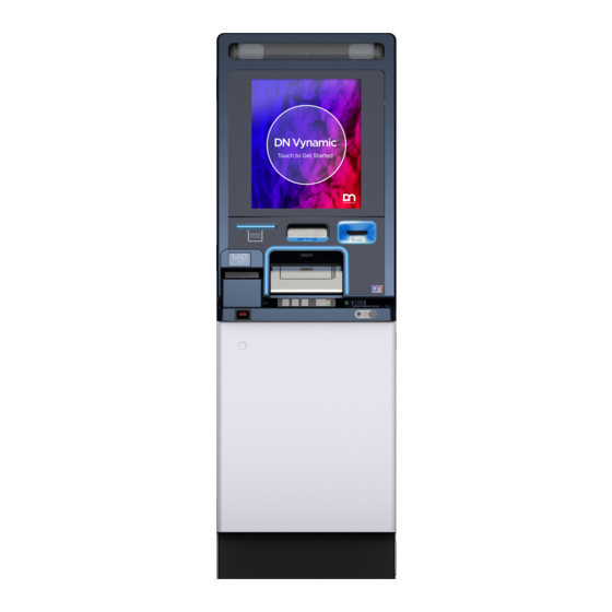
DIEBOLD NIXDORF DN 400 Series Operator's Manual (134 pages)
Lobby Multi-Function System
Brand:
DIEBOLD NIXDORF
| Category:
Cash Counter
| Size: 8 MB
Table of Contents
Table of Contents
2
Introduction
8
Symbols Used in this Manual
8
Section-Specific Warning Notes
9
Signs, Labels and Symbols
10
Table 1-1 Warning Signs Used
10
Table 1-2 Used Mandatory Signs
10
Safety
11
General Safety Precautions for the System
11
Radio Interference
14
General Power Interruption
14
Figure 2-1 Switching off the System
15
Figure 2-2 General Power Interruption - Disconnecting the Plug
15
Description
16
System Overview
16
Overall View
16
Figure 3-1 Frontload Overall View
16
Figure 3-2 Rearload Overall View
17
Figure 3-3 Rear View with Operator Panel Inspection Window
18
Figure 3-4 Rear View with Operator Panel Keyboard
19
Figure 3-6 Overall View with Electromechanical Locking
21
Chassis Components
22
Figure 3-7 Fascia Open
22
Figure 3-8 Rear Door Opened - Without Operator Panel Inspection Window
23
Front Door Opened
24
Component Carrier Pulled out
25
Figure 3-9 Component Carrier Pulled out
25
Figure 3-10 Component Carrier with CDM Pulled out
26
Figure 3-11 Component Carrier with Coin Module Pulled out
27
Figure 3-12 Component Carrier Pulled out - with Passbook Printer
28
Figure 3-13 Upper Component Carrier Pulled out
29
Figure 3-14 Component Carrier Pulled out - Rearload
30
Figure 3-15 Component Carrier with CDM Pulled out - Rearload
31
Figure 3-16 Component Carrier with Coin Module Pulled out - Rearload
32
Figure 3-17 Upper Component Carrier Pulled out - Rearload
33
Figure 3-18 Upper Component Carrier Pulled out - Rearload
34
Cash Components
35
Fascia Components
37
Figure 3-21 15" Version, Broadside Format with Functions Keys
38
Figure 3-22 15" Version, Broadside Format with Function Keys and Coin Dispenser
39
Figure 3-23 15" Version, Broadside Format with Check Deposit Module and Passbook Printer
40
Figure 3-24 19" Version, Portrait Format Without Function Keys, with Coin Dispenser
41
Figure 3-25 19" Version, Broadside Format with CDM and Coin Dispenser
42
Figure 3-26 Version 15" with Function Keys - Rearload
43
Figure 3-27 Guide Lights
44
Figure 3-28 Keyboard Privacy Shield
45
Safe Components
46
Figure 3-29 Safe Opened with RM4V - Frontload
46
Figure 3-30 Safe Opened with RM4H - Frontload
47
Figure 3-31 Safe Opened with CMD-V6C - Frontload
48
Figure 3-32 Safe Opened with RM4V - Rearload
49
Figure 3-33 Safe Opened with RM4H - Rearload
50
Figure 3-34 Safe Opened with CMD-V6C - Rearload
51
Cash Components
52
External Control Unit
54
Figure 3-37 External Control Unit - Overview
54
Functions of the External Control Unit
55
Table 3-1 Functions of the On/Off Button
55
LED Codes
56
Card Box (Removable)
58
Figure 3-38 Removable Card Box
58
Card Box (Lockable)
59
Figure 3-39 Lockable Card Box
59
Remote Status Indicator
60
Technical Data
62
General Installation Conditions
62
Table 3-2 Electrical Characteristics of the Supply Network
62
Environmental Conditions
65
Operation
65
Table 3-5 Climatic Environmental Conditions
65
General Information
66
Opening/Closing the Doors
66
Opening/Closing the Front Door
67
Opening/Closing the Rear Door
69
Opening/Closing the Frontload Fascia
70
Opening/Closing the Fascia with Fascia Lock
71
Opening/Closing the Operator Panel Inspection Window
73
Opening/Closing the Operator Panel
74
Starting up / Shutting down the System
75
Starting up the System
75
Shutting down the System
75
Starting T/SOP
76
Opening/Closing the Safe Door
77
Opening/Closing the Safe Door (with Factory Setting)
77
Customizing the Key and Number Combination Locks
83
Opening/Closing the Safe Door (with Customized Lock)
87
Calling up Product-Specific Software
93
Frontload
93
Rearload with Operator Panel Inspection Window (II)
94
Rearload with Operator Panel Inspection Window (I)
95
Pulling Out/Pushing in Components
96
Pulling out / Pushing in Cash Components
96
Pulling Out/Pushing in Frontload Component Carriers
99
Pulling Out/Pushing in Rearload Component Carriers
102
Opening/Closing the Additional Latching Mechanism of the Upper Unit
105
Opening the Additional Latching Mechanism of the Upper Unit
105
Closing the Additional Latching Mechanism of the Upper Unit
106
Unlocking the Physical Lock
107
Replacing the Logo
107
Branding Label Fascia
107
Adhesive Branding Label
110
Setting the Volume of the Headphone Jack
111
Card Box (Removable)
112
Function Elements
112
Emptying the Card Box (Removable)
113
Opening the Card Box
114
Closing the Card Box
116
Pushing in the Card Box
117
Card Box (Lockable)
121
Function Elements
121
Opening the Card Box
122
Closing the Card Box
123
Troubleshooting
125
General Information
125
Prerequisites for Troubleshooting
125
Maintenance
126
Cleaning Housings
126
Table 6-1 Approved Cleaning Agents for the Housing
126
Cleaning Keyboards
127
Cleaning LCD
127
Table 6-2 Approved Cleaning Agents for Keyboards
127
Table 6-3 Approved Cleaning Agents for the LCD
127
Disposal
128
Appendix
129
Compliance Standards and Approvals
129
Declaration of Conformity
131
Environmental Protection
132
Advertisement
Advertisement
Related Products
DIEBOLD NIXDORF DN Series 100D FL
DIEBOLD NIXDORF DN Series K32
DIEBOLD NIXDORF DN 490
DIEBOLD NIXDORF DN 200 Series
DIEBOLD NIXDORF DN Series
DIEBOLD NIXDORF DN 250 Series
DIEBOLD NIXDORF DN 470 Series
DIEBOLD NIXDORF D1156
DIEBOLD NIXDORF D1104/pc-touch
DIEBOLD NIXDORF D1064
DIEBOLD NIXDORF Categories
Touch terminals
Monitor
Cash Counter
Printer
Motherboard
More DIEBOLD NIXDORF Manuals
Login
Sign In
OR
Sign in with Facebook
Sign in with Google
Upload manual
Upload from disk
Upload from URL