Sign In
Upload
Manuals
Brands
DIEBOLD NIXDORF Manuals
Cash Counter
CS 5500
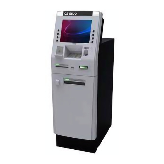
DIEBOLD NIXDORF CS 5500 Cash Dispenser Manuals
Manuals and User Guides for DIEBOLD NIXDORF CS 5500 Cash Dispenser. We have
2
DIEBOLD NIXDORF CS 5500 Cash Dispenser manuals available for free PDF download: Operating Manual
DIEBOLD NIXDORF CS 5500 Operating Manual (73 pages)
Brand:
DIEBOLD NIXDORF
| Category:
Cash Counter
| Size: 4 MB
Table of Contents
Table of Contents
4
Introduction
7
Product Description
7
Figure 1-1 CS 5500 Front-Load Lobby Cash Dispenser
8
Before Performing Maintenance Procedures
11
Maintenance Tasks
11
Using this Manual
11
General Safety Precautions
12
Warning and Caution Labels
13
Radio Interference Label
14
Terminology
14
Figure 1-2 Taiwan Class a Label
14
Devices in the Cash Dispenser
15
Access Points Used by the Consumer
15
Figure 2-1 Access Points Used by the Consumer
16
Fascia Mirror
17
Motorized Card Reader Slot
17
Dip Card Reader
17
Secure Card Reader
17
Fingerprint Reader (Optional)
17
Enhanced Biometric Fingerprint Reader (Optional)
17
Consumer Keypad
17
Headphone Jack
18
Function Keypads
18
2.1.10 Consumer Display
18
Printer Slot
18
2.1.12 Dispenser Slot
18
2.1.13 Lead-Through Indicators
18
Speakers
18
Figure 2-2 Lead-Through Indicators
19
Figure 2-3 Consumer Devices in the Top Chassis
21
Figure 2-4 Motorized Card Reader
22
Dip Card Reader
23
Figure 2-5 Dip Card Reader
23
Secure Card Reader (Optional)
24
Figure 2-6 Secure Card Reader
24
Receipt Printer
25
Figure 2-7 Receipt Printer
25
Fingerprint Reader (Optional)
26
Figure 2-8 Fingerprint Reader
26
Fingerprint Reader
26
Enhanced Biometric Fingerprint Reader (Optional)
27
Figure 2-9 Enhanced Biometric Fingerprint Reader Module
27
Barcode Scanner (Optional)
28
Figure 2-10 2D Barcode Scanner
28
Contactless Card Reader (Optional)
29
Figure 2-11 Contactless Card Reader
30
Devices Used by the Operator
33
Power Supply
33
Figure 2-12 Power Supply
34
Activpower System
36
Basic Power System
37
Maintenance Mode Switch
37
Consumer Display
38
Figure 2-13 Consumer Display
38
Disk Drives
39
Devices in the Safe
40
Figure 2-15 Devices in the Safe
40
Dispenser
41
Figure 2-16 Activdispense
42
Divert Cassette and Divert bin
43
Figure 2-17 Divert/Retract Cassette and Divert bin
43
Dispense Cassettes
44
Figure 2-18 Dispense Cassettes
44
Secure Safe Door Lock
45
Figure 2-19 Safe Door Locks
45
Alarm Sensors
46
Seismic Detectors
46
Figure 2-20 Seismic Detector
46
Heat Thermostat
47
Figure 2-21 Heat Thermostat
47
Maintenance Procedures
48
Touch Points on the Cash Dispenser and Devices
49
Figure 3-1 Examples of Touch Points on the Dispenser
49
Opening the Top Chassis
50
Figure 3-2 Opening the Top Chassis
50
Closing the Top Chassis
51
Figure 3-3 Closing the Top Chassis
51
Opening the Lower Fascia
52
Figure 3-4 Opening the Lower Fascia
52
Closing the Lower Fascia
53
Figure 3-5 Closing the Lower Fascia
53
Opening and Closing the Door of the Safe
54
Figure 3-6 Locks and Handles on the Door of the Safe
54
Opening Mechanical Combination Locks (Without Mechanical Keylock)
55
Figure 3-7 Opening the Safe Door (Mechanical Lock Without Keylock)
56
Closing Mechanical Combination Locks (Without Mechanical Keylock)
57
Figure 3-8 Closing the Safe Door (Mechanical Lock Without Keylock)
58
Opening Mechanical Combination Locks (with Mechanical Keylock)
59
Figure 3-9 Opening the Safe Door (Mechanical Lock with Keylock)
60
Closing Mechanical Combination Locks (with Mechanical Keylock)
61
Figure 3-10 Closing the Safe Door (Mechanical Lock with Keylock)
62
Opening Electronic Combination Locks (Without Mechanical Keylock)
63
Figure 3-11 Opening Safe Door (Electronic Locks Without Keylock)
63
Closing Electronic Combination Locks (Without Mechanical Keylock)
64
Figure 3-12 Closing the Safe Door (Electronic Locks Without Keylock)
64
Opening Electronic Combination Locks (with Mechanical Keylock)
65
Figure 3-13 Opening the Safe Door (Electronic Locks with Keylock)
65
Closing Electronic Combination Locks (with Mechanical Keylock)
66
Accessing the Dispenser
67
Figure 3-14 Closing the Safe Door (Electronic Locks with Keylock)
67
Figure 3-15 Accessing the Dispenser
68
Accessing the Maintenance Keyboard and Mouse
69
Accessing the Motorized Card Reader, the Receipt Printer and the Processor
69
Figure 3-16 Accessing the Motorized Card Reader, the Receipt Printer and the Processor
70
Appendix A Related Documentation
71
Appendix B Cleaning the Exterior of the System
72
Glossary
73
Advertisement
DIEBOLD NIXDORF CS 5500 Operating Manual (71 pages)
Brand:
DIEBOLD NIXDORF
| Category:
Cash Counter
| Size: 3 MB
Table of Contents
Table of Contents
3
Introduction
6
Before Performing Maintenance Procedures on the Cash Dispenser
6
Figure 1-1 CS 5500 Original Version Rear-Load Lobby Cash Dispenser
7
Maintenance Tasks
8
Figure 1-2 CS 5500 Full-Height, Rear-Load Lobby Cash Dispenser
8
Using this Manual
9
Observing Safety Precautions
9
Radio Interference Label
10
Terminology
11
Figure 1-3 Taiwan Class a Label
11
Cash Dispenser Devices
12
Consumer Interface
12
Access Points
12
Figure 2-1 Features on the Cash Dispenser Fascia
14
Lead-Through Indicators
15
Figure 2-2 Lead-Through Indicators
15
Devices in the Top Chassis
16
Devices Used by the Consumer
16
Figure 2-3 Consumer Devices in the Top Chassis of the CS 5500 Original Version Rear-Load System
17
Figure 2-4 Consumer Devices in the Top Chassis of the CS 5500 Full-Height, Rear-Load System
18
Figure 2-5 Motorized Card Reader
19
Figure 2-6 Dip Card Reader
20
Figure 2-7 Active Edge Card Reader
20
Figure 2-8 Receipt Printer
21
Figure 2-9 Fingerprint Reader with Its Cover
22
Figure 2-10 Biometric Finger Print Reader
23
Figure 2-11 2D Barcode Scanner
23
Figure 2-12 Contactless Card Reader
24
Devices in the Fascia and Top Chassis Used by the Operator
25
Figure 2-13 Contactless Card Reader (Asia Pacific Only)
25
Figure 2-14 Fascia and Top Chassis Devices Used by the Operator in the CS 5500 Original Version Rear-Load System
26
Figure 2-15 Fascia and Top Chassis Devices Used by the Operator in the CS Full-Height 5500 Rear-Load System
27
Figure 2-16 10.4-Inch Rear Display with Touch Screen
28
Figure 2-17 All-In-One Module-Consumer Display
29
Figure 2-18 Maintenance Keyboard
30
Figure 2-19 Journal Printer
32
Devices in the Safe
33
Figure 2-20 Safe Devices (CS 5500 Original Version Rear-Load System Shown)
33
Dispenser
34
Figure 2-21 Activdispense
34
Divert Cassette and Divert bin
35
Figure 2-22 Divert/Retract Cassette and Divert bin
35
Figure 2-23 Activdispense Cassettes
36
Secure Safe Door Lock
37
Figure 2-24 Safe Door Locks (CS 5500 Original Version Rear-Load System Shown)
38
Alarms Sensors
39
Seismic Detectors
39
Figure 2-25 Seismic Detector
39
Heat Thermostat
40
Figure 2-26 Heat Thermostat
40
Top Chassis and Safe Maintenance
41
Cash Dispenser and Device Touch Points
42
Figure 3-1 Examples of Touch Points on the Activdispense
42
Accessing the Top Chassis (Original Version System)
43
Opening the Top Chassis (Full-Height System)
43
Figure 3-2 Opening the Top Chassis (Original Version System)
43
Figure 3-3 Opening the Top Chassis (Full-Height System)
44
Figure 3-4 Latch Release Bracket for Fascia and Rear-Load Tray (Full-Height System)
45
Figure 3-5 Opening the Top Chassis to Extend the Upper Top Chassis Rear-Load Tray (Full-Height System)
46
Opening the Safe Door
47
Figure 3-6 Safe Door Locks and Handles
47
Figure 3-7 Open the Safe Door (CS 5500 Original Version Rear-Load System Shown)
49
Opening the Mechanical Combination Locks (Lagard 3390EX)
50
Opening the S&G 6124 Electronic Lock
50
Figure 3-8 Opening the Mechanical Combination Lock
50
Opening the Cencon® System 2000 GEN 2 Electronic Lock
51
Figure 3-9 Entering the Combination on the Cencon® System 2000 GEN 2
51
Figure 3-10 Operating the Cencon® System 2000 GEN 2 Lock
52
Opening the S&G 6880 Keylocks
53
Opening the Lagard 2270 Keylocks
53
Figure 3-11 Opening the S&G 6880 Keylock
53
Figure 3-12 Opening the Lagard 2270 Keylock
53
Closing the Safe Door
54
Figure 3-13 Closing the Safe Door (CS 5500 Original Version Rear-Load System Shown)
54
Closing the Mechanical Combination Locks (Lagard 3390EX)
55
Closing the S&G 6124 Electronic Lock
55
Figure 3-14 Closing the Mechanical Combination Lock
55
Closing the Cencon GEN 2 Electronic Locks
56
Closing the S&G 6880 Keylocks
56
Figure 3-15 Closing the Cencon 2000 GEN 2 Electronic Lock
56
Figure 3-16 Closing the S&G 6880 Keylock
56
Closing the Lagard 2270 Keylocks
57
Figure 3-17 Closing the Lagard 2270 Keylock
57
Accessing Modules and Components in the Cash Dispenser
58
Figure 3-18 Accessing the Dispenser (CS 5500 Original Version Rear-Load System Shown)
59
Accessing the Maintenance Keyboard and Mouse and Rear Operator Display
60
Figure 3-19 Rear Operator Display (Full-Height System Shown)
61
Accessing the Lower Door
62
Figure 3-20 Removing the Lower Door (CS 5500 Original Version Rear-Load System Shown)
62
Accessing the Motorized Card Reader, Receipt Printer, and Processor
63
System)
63
Figure 3-21 Accessing the Motorized Card Reader, Receipt Printer, and Processor (CS 5500 Original Version Rear-Load System Shown)
64
Figure 3-22 Closing the Top Chassis Door (CS 5500 Original Version Rear-Load System Shown)
65
Accessing the Motorized Card Reader, Receipt Printer, and Processor (Full-Height System)
66
Appendix A Related Documentation
70
Advertisement
Related Products
DIEBOLD NIXDORF CS 5550
DIEBOLD NIXDORF CS 7750
DIEBOLD NIXDORF CS 7790
DIEBOLD NIXDORF CS 7780
DIEBOLD NIXDORF CS 7700
DIEBOLD NIXDORF CINEO C4060
DIEBOLD NIXDORF CINEO C1010
DIEBOLD NIXDORF C2120
DIEBOLD NIXDORF DN 400 Series
DIEBOLD NIXDORF DN 490
DIEBOLD NIXDORF Categories
Touch terminals
Monitor
Cash Counter
Printer
Motherboard
More DIEBOLD NIXDORF Manuals
Login
Sign In
OR
Sign in with Facebook
Sign in with Google
Upload manual
Upload from disk
Upload from URL