Sign In
Upload
Manuals
Brands
DFE Manuals
Controller
STEADYWEB 6
DFE STEADYWEB 6 Manuals
Manuals and User Guides for DFE STEADYWEB 6. We have
3
DFE STEADYWEB 6 manuals available for free PDF download: Technical Reference Manual, Operating Instructions Manual, Quick Start Manual
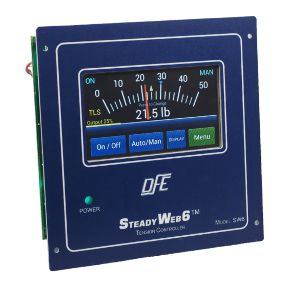
DFE STEADYWEB 6 Technical Reference Manual (72 pages)
Digital Tension Controller
Brand:
DFE
| Category:
Controller
| Size: 6 MB
Table of Contents
Table of Contents
5
FIGURE 1. Front View of Steadyweb6
7
General Description
7
Examples of Tension Zones
8
Tension Zones
8
Specifications
9
Versions of the Controller
9
Environmental Conditions
11
Standard Features
11
Accessories
13
Options
13
Dimensions
14
Enclosure Version Dimensions and Views
14
Panel Version Dimensions and Views
14
High Voltage Output Enclosure Dimensions for Version V
15
Pneumatic Enclosure Dimensions for Version P
15
Selection of Mounting Location
15
Safety & EMC Requirements
16
Enclosure Version Service Access
17
Installation Instructions
18
Transducer Voltage Selection
18
Control Output Selection
19
Emergency Stop Configuration
20
Output Jumpers
20
Tension Output Selection
20
Customer +10/15V Output Selection
21
Setup Jumpers
21
Power Electrical Connections
22
VDC Power Electrical Connections
22
AC Power Electrical Connections
23
Standard Electrical Connections
23
Standard and 0-10VDC Control Board Electrical Connections
24
Control Board Transducer Electrical Connections and Remote Option
25
Option Card Mounting Locations
26
Pulse Tachometer Electrical Connections
26
Pulse Tachometer Option Card Electrical Connections
26
DC Tachometer Electrical Connections
27
DC Tachometer Option Card Electrical Connections
27
Relay Electrical Connections
27
Relay Option Card Electrical Connections
27
VDC Connections for Brakes and Clutches
28
Communication Options Cards Electrical Connections
29
Main Interface Description
30
Display Modes Descriptions
30
External Output Module Cable Connections
29
High Voltage Output Module Electrical Connections
29
Steadyweb6 User Interface
30
Menu Display Mode and Navigation
31
Main Menu Screen
31
PID Tune View
32
Tension Calibration
33
PID Tune View Screen
33
Selection of Calibration Weight
33
Selection of Tension Range
33
Selection of Tension Source
33
Selection of Tension Units
33
Review of Calibration Settings
34
Selection of Transducer Type
34
Web Path for Calibration
34
Line/Roll Speed Input Calibration
35
Zero Operation Complete
34
Zero Transducer Screen
34
Cal Not Ready
35
Cal Ready
35
Cal Successful
35
DC Tachometer Calibration
36
DC Tachometer
36
Pulse Tachometer Calibration
37
Pulse Tachometer
38
Diameter Input Calibration
39
Signal Filtering
40
Control Feedback Modes
41
Unwind Zone Setup
41
Intermediate Zone Setup
42
Rewind Zone Setup
43
Soft Start Setup
44
Sample and Hold/Ratio Setup
45
Tension Limit Switch Setup
46
Diameter Alarm Setup
46
Inputs Setup
47
Communication Options Setup
48
Relay Option Setup
48
Anti Tamper Lockup Jumper
49
PID Control Tuning
50
Tuning Procedure
50
Tuning Examples
51
Anti-Tamper/Security Lockout
49
Power on Settings
49
Tension on Relay Option
49
Derivative Noise
51
Advanced Tuning Adjustments
52
Diameter Compensation
52
Tuning Screen Showing Overshoot
51
Tuning Screens Showing Adjustment Responses
51
Screens Showing Wobble
52
Acceleration Compensation
53
Diameter Compensation PID Transition
53
Basic Operation
54
Display Adjustments
54
Saving and Recalling Setups
54
Transferring Setups to PC Via USB
54
Setting Auto/Manual Setpoints
54
Using Taper
54
Resetting TLS Alarms
54
Resetting Diameter Alarm
54
Zeroing Tension
54
Section Eight Care and Maintenance
55
Error Messages
56
General Troubleshooting Tips
56
Diagnostic Screens
58
Section Ten Replacement Parts
61
APPENDIX : a Location of Jumpers and Adjustments (Figure 49)
62
Control Board Showing Jumper Locations
62
B Menu Hierarchy (Figure 50)
63
Menu Hierarchy
63
C Electrical Connections (Figures 51-52)
64
Standard and 0-10Vdc Control Board Electrical Connections
64
Control Board Transducer Electrical Connections and Remote Option
65
D Transducer Electrical Connections (Figure 53-54)
66
Models C, RS, F, TR, and NW Transducer Wiring
66
RFA, LT, and VNW Transducer Wiring
67
E Typical Tensions of Various Materials
68
F Environmental Terms
69
Terms and Conditions of Sale and Shipment
70
Index
71
Advertisement
DFE STEADYWEB 6 Operating Instructions Manual (20 pages)
Digital Tension Controller
Brand:
DFE
| Category:
Controller
| Size: 0 MB
Table of Contents
Table of Contents
5
Main Interface Description
7
FIGURE 1. Steadyweb6 User Interface
7
Display Mode Descriptions
8
Tension Display Modes
8
Locations of Toggle Buttons/Indicators in Display
8
Screen Showing Side Arrows
8
Menu Mode and Navigation
9
Analog Meter Display
9
Trend Line Graph Display
9
Main Menu
10
Basic Operation
11
Display Adjustments
11
Saving and Recalling Setups
11
Display Configuration Menu
11
Select Location to Store
12
Name Setup Screen
12
Confirm Save Setup
12
Recall Setup
12
Select Setup to Delete
12
Auto Tension Setpoint / Manual Output Setting
13
Taper Tension
13
Adjusting Setpoint
13
Enable Taper Tension
13
Set Taper Percentage
13
TLS Alarms and Resetting Them
14
Taper Setpoint on Meter
14
Taper Display on Trendline
14
Examples of When to Run Taper
14
Resetting Diameter Alarm
15
TLS Setpoint Shown
15
Reset TLS Screen
15
Index
19
DFE STEADYWEB 6 Quick Start Manual (12 pages)
Tension Controller
Brand:
DFE
| Category:
Controller
| Size: 0 MB
Table of Contents
General Description
3
Installation Instructions
3
User Interface
5
Troubleshooting
10
Advertisement
Advertisement
Related Products
DFE SteadyWeb
DFE SW6
DFE WebHandler 3
DFE Categories
Controller
Amplifier
Transducer
Measuring Instruments
Farm Equipment
More DFE Manuals
Login
Sign In
OR
Sign in with Facebook
Sign in with Google
Upload manual
Upload from disk
Upload from URL