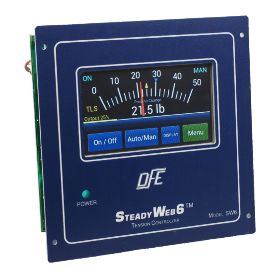
DFE STEADYWEB 6 Technical Reference Manual
Digital tension controller
Hide thumbs
Also See for STEADYWEB 6:
- Operating instructions manual (20 pages) ,
- Quick start manual (12 pages)

Subscribe to Our Youtube Channel
Related Manuals for DFE STEADYWEB 6


Summary of Contents for DFE STEADYWEB 6
- Page 1 TECHNICAL REFERENCE MANUAL Digital Tension Controller ™ TEADY DOC 801-2540...
- Page 2 Telephone: (603) 332-6150 Fax: (603) 332-3758 E-mail: info@dfe.com Internet: www.dfe.com ©2019 Dover Flexo Electronics, Inc. All rights reserved. Dover Flexo Electronics has made reasonable effort to ensure accuracy of this document. However NO WARRANTY, whether expressed or implied, is given regarding the completeness or correctness of information in this document.
- Page 3 Failure to follow the manual's instructions and practice safe working habits could result in property damage, personal injury and/or death WARNING: Before servicing the SteadyWeb 6, power should be removed from the device. Failure to do so could result in property damage, personal injury and/or death. CAUTION: The SteadyWeb 6 contains circuit boards with static sensitive devices.
-
Page 5: Table Of Contents
TABLE OF CONTENTS SECTION ONE PRODUCT DESCRIPTION PAGE 1.1 General Description ..........1 1.2 Tension Zones . - Page 6 SECTION NINE TROUBLESHOOTING 9.1 General Troubleshooting Tips ........50 9.2 Error Messages .
-
Page 7: General Description
PRODUCT DESCRIPTION 1.1 GENERAL DESCRIPTION ™ The SteadyWeb 6 is a digital tension controller designed to automatically maintain tension of any continuous material at a value selected by the equipment operator. The controller combines ease of use with powerful control features and capability that allow for effortless configuration and utilization over a wide variety of tension control applications. -
Page 8: Tension Zones
1.1 GENERAL DESCRIPTION continued..2. Tension Regulator The second component is the tension regulator. The controller compares the measured tension to the Auto setpoint value and adjusts an output signal to equalize the measured and desired tension. The regulator function is performed by software and may be influenced by other signal inputs, such as web speed and roll diameter, as dictated by operator-adjustable settings. -
Page 9: Versions Of The Controller
24V brakes and clutches up to 2.5A drawn current. Devices drawing more than 2.5A at 24V can be accommodated with guidance from DFE Engineering. To operate brakes or clutches at more than 24V, including eddy current clutches, the 45 and 90 Vout options are available in an outboard module which is fed a 0-10V signal from the D version of the controller (described above) and employs a Silicon Controlled Rectifier (SCR) to deliver variable voltage of up to 90VDC. - Page 10 1.4 SPECIFICATIONS continued . . . Transducer Excitation: Tension Output: • 5VDC for STD transducers, 10VDC for XR All Versions: transducers (automatically software set per sensed • 0 to +10VDC OR 0 to 1mA (jumper-selectable) transducer resistance, or manually fixed through user •...
-
Page 11: Environmental Conditions
1.4 SPECIFICATIONS continued . . . High Voltage Output Module (Version V only): Optional RS232 Card: Power Input: • Selectable Baud Rate: 4800, 9600, 14400, 19200 • 115 OR 230VAC 50/60Hz single phase • Modbus RTU Interface, Jumper Configurable Null Modem or Standard communication Note: 115 / 230 VAC factory set. - Page 12 1.6 STANDARD FEATURES continued... • Automatic Excitation Voltage Selection. An intelligent transducer excitation system allows the controller to automatically adjust the excitation voltage in accordance with the connected transducer type; 5VDC for Standard (STD) transducers or 10VDC for Extended Range (XR) transducers. The system is also capable of detecting transducer wiring errors or fault conditions, such as a short circuit or open circuit conditions.
-
Page 13: Options
Taper is adjustable from 0 to 100%. 1.8 ACCESSORIES • Remote Tension Meter. Analog, 1 mA (DFE P/N: 722-1385) supplied as a single unit. Must be installed by user. This meter is also available in its own enclosure (DFE P/N: 723-2682, meter included). -
Page 14: Dimensions
INSTALLATION The Anti-Tamper / Security Lockout is a jumper, shipped in the unlocked position, and may be used to prevent unauthorized changes to the controller. Refer to Section 5.14 for more detail regarding this feature. 2.1 DIMENSIONS inches (mm) Figure 3 - ENCLOSURE VERSION DIMENSIONS and VIEWS Figure 4 - PANEL VERSION DIMENSIONS and VIEWS... -
Page 15: Selection Of Mounting Location
2.1 DIMENSIONS continued... Figure 5 - PNEUMATICS ENCLOSURE DIMENSIONS FOR VERSION P Figure 6 - HIGH VOLTAGE OUTPUT ENCLOSURE DIMENSIONS FOR VERSION V 2.2 SELECTION OF MOUNTING LOCATION 1. Enclosure Mount Versions Select a mounting location on the machine frame or a wall that will provide convenient operator interaction and ™... -
Page 16: Safety & Emc Requirements
Unlike for the 90V and 45V output versions, the 24V version is fully enclosed within the SteadyWeb 6 Enclosure Mount and Panel Mount versions, and requires no separate high voltage output enclosure. It requires a dedicated AC power feed. In addition, a signal cable must be run between the Vout module and the controller. -
Page 17: Enclosure Version Service Access
Other cables manufactured by DFE also meet this requirement. Contact DFE for more information. In addition to the transducer cable shielding, a shielded meter cable (DFE P/N: 721-0967, 15 ft., other lengths available) and meter in enclosure (DFE P/N: 723-2682) are required when an accessory meter is used. -
Page 18: Installation Instructions
This module is not sensitive to mounting at any angle. 2.5 TRANSDUCER VOLTAGE SELECTION ™ Unlike previous DFE products, the transducer excitation voltage in the SteadyWeb 6 is not normally set via a ™ jumper or switch setting. The SteadyWeb... -
Page 19: Control Output Selection
(see Figure 13, Control Board Transducer Electrical Connections and Remote Option). In certain situations the Auto Excitation Voltage feature may be undesirable, such as when using DFE LT transducers or other unique transducers that don't feature the normal resistance ranges of DFE Standard and Extended Range transducers. -
Page 20: Tension Output Selection
Figure 8 - OUTPUT JUMPERS 2.7 TENSION OUTPUT SELECTION The tension output can be configured as a 0-10V or 0-1mA signal representing tension by setting jumper JP4 on the control board (see Figure 8, Output Jumpers). The 0-1mA output is designed to drive a 50 Ohm meter. If a 0-10V output is required, place the jumper on pins and 2 and 3 (labeled 0-10V) on JP4. -
Page 21: Customer +10/15V Output Selection
2.8 EMERGENCY STOP CONFIGURATION continued... The Output During ESTOP setting, also located in the Setup Menu > Tension Control Setup menu, allows for the selection of High or Low Emergency Stop output. This setting allows the user to specify the software output level duringan Emergency Stop condition. -
Page 22: Power Electrical Connections
2.10 POWER ELECTRICAL CONNECTIONS Make wiring connections as follows: 1. The insulation rating of all line voltage wiring must be at least 600V. 2. Keep line voltage wiring physically separated from signal wiring at the terminal block and at any other point in the installation. -
Page 23: Standard Electrical Connections
Transducer connections Enclosure mount units are equipped with Amphenol connectors that facilitate connection with DFE transducers. Panel mount units require wiring of the transducers directly to the Transducer terminal block (TB4). The Transducer terminal block contains a 6 terminal transducer interface. -
Page 24: Standard And 0-10Vdc Control Board Electrical Connections
Figure 12 - STANDARD AND 0-10VDC CONTROL BOARD ELECTRICAL CONNECTIONS... -
Page 25: Control Board Transducer Electrical Connections And Remote Option
Figure 13 - CONTROL BOARD TRANSDUCER ELECTRICAL CONNECTIONS AND REMOTE OPTION... -
Page 26: Option Card Mounting Locations
2.12 OPTION CARD MOUNTING LOCATIONS ™ The SteadyWeb 6 main control board contains plugs and mounting hole locations for option card placement, allowing for a modular assembly. There are four main option card insertion areas, as shown in Figure 14, Option Card Mounting Locations. -
Page 27: Dc Tachometer Option Card Electrical Connections
2.14 DC TACHOMETER OPTION CARD ELECTRICAL CONNECTIONS Figure 16 – DC TACHOMETER ELECTRICAL CONNECTIONS 2.15 RELAY OPTION CARD ELECTRICAL CONNECTIONS To minimize electromagnetic interference and extend the life of the relay, a resistor capacitor (RC) network may be needed across the relay connections. Any arcing should be minimized. The resistor wattage and capacitor voltage ratings should be sized to handle worse case conditions of the application, including spikes caused from switching inductive loads. -
Page 28: Vdc Connections For Brakes And Clutches
24VDC for powering the controller. This will inhibit brown-outs ofthe controller during peak demand on the controlled device. For applications demanding 24VDC above 2.5A, consult DFE Engineering Figure 18 – 24 VDC CONNECTIONS FOR BRAKES AND CLUTCHES... -
Page 29: External Output Module Cable Connections
Please refer to the specific communication card option manual for more information on wiring and configuring the card. Specific communication card manuals are shipped with the option card, or can be downloaded from the DFE website, www.dfe.com. -
Page 30: Main Interface Description
All controller functions are context driven, and operate with color-coded buttons on the display. There are no mechanical knobs, switches or buttons to operate. Please refer to Section 1.1 of the Operating Instructions (DFE P/N 801-2539) for a more detailed description of the User Interface. -
Page 31: Menu Display Mode And Navigation
Please refer to Section 1.2.2 of the Operating Instructions (DFE P/N 801-2539) for a more detailed description of the Menu Display Mode, the Operator Menu in particular, and Navigation through the menus in general. -
Page 32: Pid Tune View
3. DIAGNOSTIC MENU - Under the Diagnostic Menu, the following choices are available (All are Read Only, and are useful for discussions with DFE Tech Support), with all other choices greyed out: • Version Menu - Displays versions and revisions of the software and hardware •... -
Page 33: Tension Calibration
CALIBRATION 4.1 TENSION CALIBRATION When using the standard transducer connection (as opposed to an RTA input), tension calibration must be completed before the controller is able to display or control tension. 1. Standard Transducer Calibration In preparation for transducer calibration, select an appropriate calibration weight. Larger weights (in reference to the full scale range) tend to give more accurate calibration, but can be unwieldy for large tension ranges. -
Page 34: Selection Of Transducer Type
BACK to return to the prior screen. After pressing OK, the SteadyWeb 6 zeros out the roll weight and a progress bar moves across the screen, after which the message “Zero operation complete" comes up in green characters, as shown on the Zero successful screen (Fig. -
Page 35: Line/Roll Speed Input Calibration
4.1 TENSION CALIBRATION continued... 1. Standard Transducer Calibration continued..Fig. 33 shows the Cal NOT Ready screen. The Calibrate button is gray, accompanied by an error message in red characters. This error message appears if the transducers are not properly wired to the indicator, if the calibration weight is insufficient for the application, or if the weight is not properly loading the transducer roll. -
Page 36: Dc Tachometer Calibration
4.2 LINE/ROLL SPEED INPUT CALIBRATION continued... 1. 0-10V Signal When using a 0-10V signal, no calibration is necessary. The signal should be wired directly into the control board's Signal terminal block (see Figure 12). A Line speed signal should be wired into (TB3) terminal 19 (LINE IN) and 21 (GROUND) and a Roll Speed input should be wired into (TB3) terminal 20 (ROLL IN) and 22 (GROUND) (see Section 2.11, Figure 12. -
Page 37: Pulse Tachometer Calibration
4.3 DC TACHOMETER CALIBRATION continued... TACH OPTION CARD slot. For this reason, a 0-10V signal should not be fed to both the control board's Signal terminal block (TB3) LINE IN or ROLL IN terminal and the corresponding tachometer input option card. The Line and Roll signal should only come from a single source, the TB3 terminal block OR a tachometer option card, and the terminal block input should never be used while the corresponding tachometer option card slot is populated with a tachometer card. -
Page 38: Pulse Tachometer
4.4 PULSE TACHOMETER CALIBRATION continued..The positive output of the pulse tachometer should connect to terminal 3 (+) of the Pulse Tachometer input card terminal block (TB600). The negative output of the pulse tachometer should connect to terminal 2 (-) of the Pulse Tachometer Input card terminal block (TB600) (see Section 2.13, Pulse Tachometer Option Card Electrical Connections). -
Page 39: Diameter Input Calibration
4.4 PULSE TACHOMETER CALIBRATION continued..Pulse Tachometer Input card output voltage follows speed changes. Stop the machine and verify the output voltage drops to 0.0V. Note: If the OUTPUT and GROUND test points (TP601 and TP600) are difficult to access, the tachometer option card output signal can be read from the control board Signal terminal block (TB3) connections;... -
Page 40: Signal Filtering
4.5 DIAMETER INPUT CALIBRATION continued... To use the Tachometer Ratio Calculation feature, Line and Roll inputs must be present and calibrated if required (see section, 4.2 Line/Roll Speed Input Calibration). 4. Testing the Diameter Measurement In the Operator Menu > Display Configuration menu, set the Diameter Display setting to On. This will display diameter information in the tension display screens in circular graph form, as well as text readout for both diameter percentage and the diameter value (based upon the Core Diameter, Max Full Roll Dia and Diameter Units settings). -
Page 41: Control Feedback Modes
SETUP 5.1 CONTROL FEEDBACK MODES The controller features three Control Feedback Modes. The mode of use is specified by the Control Feedback setting, located in the Setup Menu > Tension Control Setup menu. The three feedback modes are Standard Closed Loop, Line Speed Follow Tension Trim and Diameter Compensated Line Speed Follow Tension Trim. -
Page 42: Intermediate Zone Setup
5.2 UNWIND ZONE SETUP continued... 4. Q: What type of Actuator device will you be feeding? A: Brake Configure the output for 0-10V or 4-20mA as required to drive your brake configuration. If ordered as a Version P, use the 4-20mA output to the pneumatics module. Ensure the Control Output setting is set to Standard. -
Page 43: Rewind Zone Setup
5.3 INTERMEDIATE ZONE SETUP continued... 4. Q: Will you be using the TLS (Tension Limit Switch) feature? This feature is used to provide an alarm when web tension exceeds or drops below user specified levels. See Section 5.7, Tension Limit Switch Setup, for more information. -
Page 44: Soft Start Setup
5.4 REWIND ZONE SETUP continued... 7. Tune the control loop as specified in Section 6, Tuning Adjustments. In applications with a large difference between core and full roll diameter, the Diameter Compensation feature may be useful. In this case, a diameter input signal is required, see Section 4.5, Diameter Input Calibration. -
Page 45: Sample And Hold/Ratio Setup
5.5 SOFT START SETUP continued.. 3. Actuation by External Contact Closure To activate, navigate to the Setup Menu > Soft Start Setup menu and set the Switched Soft Start setting to On.Connect an external switch or relay contact to the Signals terminal block (TB3) terminal 13 (SOFT) and terminal 11 (GROUND) (see Section 2.11, Standard Electrical Connections). -
Page 46: Tension Limit Switch Setup
5.7 TENSION LIMIT SWITCH SETUP The TLS (Tension Limit Switch) feature is used to provide an alarm when web tension exceeds or drops below user specified levels. When a TLS condition occurs, the controller issues a visual alarm to the tension display and can also activate a Relay contact. -
Page 47: Inputs Setup
5.8 DIAMETER ALARM SETUP continued... Also within the Diameter Setup menu, set the Minimum Diameter Trip Point or Maximum Diameter Trip Point setting to the desired trip point, noting that only the alarm for minimum Core Diameter may be set in an unwind zone, for maximum Full Roll Diameter in a rewind zone and that neither may be set in an intermediate zone. -
Page 48: Relay Option Setup
Communication Option cards are explained in the SW6 Communications Insert (DOC 801-2542). The Communications Insert will be shipped with the card, or can be downloaded from the DFE website, www.DFE.com. If a Communication Option card is not installed, all Communication related settings should be... -
Page 49: Tension On Relay Option
5.12 TENSION ON RELAY OPTION Used to enable a drive or other input when tension is on. See Section 5.9 for setup. Not compatible with TLS when TLS is using a relay output. 5.13 POWER ON SETTINGS The power on Auto / Manual and Tension On / Off states can be configured with the Power On Control Mode and Power On Tension Mode settings. -
Page 50: Pid Control Tuning
TUNING ADJUSTMENTS 6.1 PID CONTROL TUNING There are three tuning adjustments that set the controller's response to tension error (error referring to the difference between the set point and the actual tension measurement). The Proportional, Integral and Derivative adjustments are also more intuitively referred to as Gain, Stability and Response. 1. -
Page 51: Tuning Examples
6.3 TUNING EXAMPLES The following figures provide some examples of the tuning parameters' effect on overall tension control. In these figures, the controller's Ratio Target setting is set to Setpoint and the Ratio Multiplier setting is set to 1.5. Pulling the RATIO terminal to ground in this configuration causes the tension setpoint to instantly increase by 50%. -
Page 52: Advanced Tuning Adjustments
6.3 TUNING EXAMPLES continued... View screen to monitor both the tension and the output while tuning. Large and fast output changes can be addressed by decreasing the D and P terms and increasing the I term. Increasing the Tension Filter Time can also aid in reducing Derivative susceptibility to tension noise. -
Page 53: Acceleration Compensation
6.5 DIAMETER COMPENSATION continued... Figure 43 – DIAMETER COMPENSATION PID TRANSITION 6.6 ACCELERATION COMPENSATION To use the acceleration compensation feature, the acceleration multipliers for each PID setting, as well as the Acceleration Limit and line Acceleration Percentage settings should be programmed. The Acceleration Compensation Enable setting must then be enabled. -
Page 54: Basic Operation
As many as 30 setups, each composed of different combinations of selections and settings under the Operator Menu, may be named, saved, recalled and deleted from the SW6 by the operator. See Section 2.3 of the Operating Instructions (DFE P/N 801-2539) for additional information. 7.4 SETTING AUTO AND MANUAL SETPOINTS The Auto and Manual Setpoints are set and adjusted using "+"... -
Page 55: Section Eight Care And Maintenance
CARE AND MAINTENANCE It is not necessary to perform any type of maintenance on the controller. However, you may find it worthwhile to observe whether there is buildup of dust, debris or moisture on or near the unit after a period of time. If so, you may consider moving the unit or putting the unit in an enclosure more suited to your particular environment. -
Page 56: General Troubleshooting Tips
6150 Fax: (603) 332-3758 Email: techsupport@dfe.com. We offer experienced technicians whose responsibil- ity it is to make sure you are satisfied with your DFE equipment. They will be pleased to help you. The most common source of improper operation of tension equipment is incorrect installation of the tension transducers or using transducers of the wrong load rating. - Page 57 Section 2.11 Standard Electrical transducer strain gage. Connections. • If using non traditional high impedance transducers (not DFE STD or XR), set the Excitation Voltage setting to the voltage required for the transducers (5V Set or 10V Set). Do not use the Auto setting.
-
Page 58: Diagnostic Screens
1. Software/Hardware Versions The Diagnostic Menu > Version Menu display shows the controller's software and hardware versions. This can be useful in communication with DFE Technical support. 2. Monitoring Controller I/O The Diagnostic Menu > Read Digital Inputs display provides a real time view of the Signal terminal block (TB3) digital inputs states. - Page 59 The user may then configure the controller as they wish at their own risk. 6. Service Access Diagnostic Menu>Service Access>Enter Service Code. The Service Menu should be accessed only by, or with guidance from DFE Technical Support. Please contact us at 603-332-6150.
- Page 60 Controller's memory, returning it to a default state. Caution: This action should never be performed unless instructed to do so by DFE Technical Support. Reinitializing the controller will clear all saved Setups as well as the calibration values and the factory adjusted analog offset values.
-
Page 61: Section Ten Replacement Parts
REPLACEMENT PARTS WARNING: When replacing fuses, use only fuses with ratings as shown below. Failure to do this may compromise personal safety and may create a fire hazard! Main Circuit Boards Control Board 723-2561 User Interface Board with Encoder 723-2812 Optional Power Supply AC to DC Power Supply 144-0028, 144-0006 (ALT) -
Page 62: Appendix : A Location Of Jumpers And Adjustments (Figure 49)
Appendix A: Locations of Jumpers and Adjustments Figure 44 - CONTROL BOARD SHOWING JUMPER LOCATIONS... -
Page 63: B Menu Hierarchy (Figure 50)
Appendix B: Menu Hierarchy Figure 45 - MENU HIERARCHY... -
Page 64: C Electrical Connections (Figures 51-52)
Appendix C: Electrical Connections Figure 46 - STANDARD AND 0-10VDC CONTROL BOARD ELECTRICAL CONNECTIONS... -
Page 65: Control Board Transducer Electrical Connections And Remote Option
Figure 47 - CONTROL BOARD TRANSDUCER ELECTRICAL CONNECTIONS AND REMOTE OPTION... -
Page 66: D Transducer Electrical Connections (Figure 53-54)
Appendix D: Transducer Electrical Connections Figure 48 - MODELS C, RS, F, TR, & NW TRANSDUCER WIRING... -
Page 67: Rfa, Lt, And Vnw Transducer Wiring
Figure 49 - MODELS RFA, LT, & VNW TRANSDUCER WIRING... -
Page 68: E Typical Tensions Of Various Materials
Appendix E: Typical Tensions for Various Materials TYPICAL TENSIONS FOR WEB MATERIALS ACETATE 0.5 lb. per mil per inch of width FOIL Aluminum 0.5 lb. per mil per inch of width Copper 0.5 lb. " CELLOPHANE 0.75 lb. per mil per inch of width NYLON 0.25 lb. -
Page 69: F Environmental Terms
Appendix F: Environmental Terms OVERVOLTAGE CATEGORY: Classification of parts of installation systems or circuits with standardized limits for transient overvoltages, dependent on the normal line voltage to earth. POLLUTION: Any addition of foreign matter, solid, liquid or gaseous (ionized gases), that may produce a reduction of dielectric strength or surface resistivity. -
Page 70: Terms And Conditions Of Sale And Shipment
(SPRs), product manufactured specially to customer specifications, and 3. GOVERNING LAW non-DFE product purchased on customer behalf shall not be returnable This contract shall be governed by and construed according to the laws for any reason. All material returned, for whatever reason, shall be sent of the state of New Hampshire, U.S.A. -
Page 71: Index
INDEX +10/15V Customer Output......6, 15 Mounting Location 0-10 Volt Control Output ....... 2-4 enclosure, panel . - Page 72 307 PICKERING ROAD ROCHESTER, NEW HAMPSHIRE 03867-4630 U.S.A TEL: 603-332-6150 FAX: 603-332-3758 E-mail: info@dfe.com Internet: www.dfe.com CANADA MEXICO UNITED KINGDOM TAIWAN KOREA CHINA INDIA AUSTRALIA SOUTH AFRICA ©2019 DOVER FLEXO ELECTRONICS, INC DOC 801-2540 R3 ALL RIGHTS RESERVED BRAYSHAW 11/19...
Need help?
Do you have a question about the STEADYWEB 6 and is the answer not in the manual?
Questions and answers