Table of Contents
Advertisement
Quick Links
Advertisement
Table of Contents

Subscribe to Our Youtube Channel
Related Manuals for DFE SW6 Series


Summary of Contents for DFE SW6 Series
- Page 1 OPERATING INSTRUCTIONS Digital Tension Controller TEADY ™ DOC 801-2539...
- Page 2 Telephone: (603) 332-6150 Fax: (603) 332-3758 E-mail: info@dfe.com Internet: www.dfe.com ©2019 Dover Flexo Electronics, Inc. All rights reserved. Dover Flexo Electronics has made reasonable effort to ensure accuracy of this document. However NO WARRANTY, whether expressed or implied, is given regarding the completeness or correctness of information in this document.
- Page 3 READ THIS! *** SAFETY INFORMATION *** Please read this manual prior to installing and operating the controller. Take care to follow local codes and only allow properly trained individuals to operate or service the equipment. Failure to follow the manual's instructions and practice safe working habits could result in property damage, personal injury and/or death WARNING: Before servicing the SteadyWeb 6, power should be removed from the device.
-
Page 5: Table Of Contents
TABLE OF CONTENTS SECTION ONE USER INTERFACE OVERVIEW PAGE 1.1 Main Interface Description........1 1.2 Display Mode Descriptions . -
Page 7: Main Interface Description
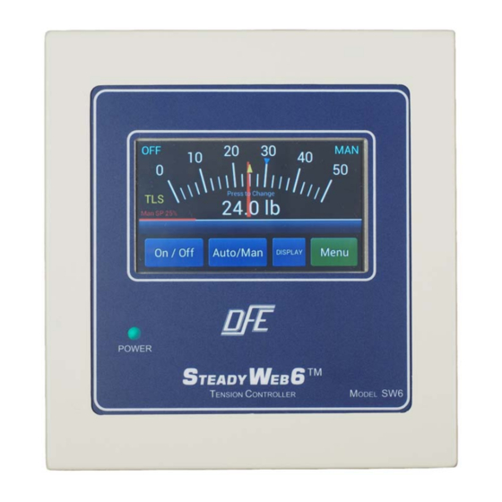
USER INTERFACE OVERVIEW ™ Figure 1 – STEADYWEB 6 USER INTERFACE 1.1 MAIN INTERFACE DESCRIPTION The Steady Web 6 accepts all instructions and displays all information via a 5" touchscreen display (Fig. 1). All controller functions are context driven, and operate with color-coded buttons on the display. There are no mechanical knobs, switches or buttons to operate. -
Page 8: Display Mode Descriptions
Sometimes meeting the necessary conditions requires permission-based access and actions in accordance with the Technical Reference Manual (DFE P/N 801-2540). On navigation screens, pressing the Back button will return the prior screen. If the Back button has been replaced with another function, the use of which is not desired, the screen may be exited via the Display button instead. -
Page 9: Menu Mode And Navigation
Section 2.6, TLS ALARMS AND RESETTING THEM. This trend-line graph display also appears repeatedly in the Technical Reference Manual (DFE P/N 801-2540) on PID Tune View displays which allow for real-time P, I, and D adjustments while viewing the controller output and tension. -
Page 10: Main Menu
(See Section 2.3.2 for more detail). 2. DIAGNOSTIC MENU - Under the Diagnostic Menu, the following choices are available (All are Read Only, and are useful for discussions with DFE Tech Support), with all other choices greyed out: •... -
Page 11: Basic Operation
This also applies to the PID tune screen referenced repeatedly in the Technical Reference Manual (DFE P/N 801-2540). • Line Speed Display - Choose Auto, On or Off and press SAVE. When in Auto, if line speed is required for control, it will be displayed by default. -
Page 12: Select Location To Store
2.3 SAVING, RECALLING AND DELETING SETUPS continued... A Saved Setup is a group of settings saved together in a named setup, and is also preserved in non- volatile memory. Only by saving a named setup after changing one or more settings in that named setup (overwriting), or by deleting the named setup, can saved settings be lost. -
Page 13: Auto Tension Setpoint / Manual Output Setting
2.4 AUTO TENSION SETPOINT AND MANUAL OUTPUT SETTING Pressing or tapping the tension display area on either the Analog Meter or Trend-line Graph display will bring up “+” and “-“ buttons (Fig. 13), which are used to adjust the auto tension setpoint by pressing or holding them down. -
Page 14: Tls Alarms And Resetting Them
2.5 TAPER TENSION continued.. Figure 16 - TAPER SETPOINT ON METER Figure 17 - TAPER DISPLAY ON TRENDLINE Finding the right taper percentage for a particular process may take some experimentation in adjusting both the auto tension setpoint and the taper percentage. See the table below for common winding defects and corresponding corrective actions: Location Tight/Loose... -
Page 15: Resetting Diameter Alarm
2.6 TLS, ALARMS AND RESETTING THEM continued... Figure 19 - TLS SETPOINT SHOWN Figure 20 - RESET TLS SCREEN 2.7 RESETTING DIAMETER ALARM The diameter alarm alerts the operator that the roll has reached a size requiring attention. A flashing red message to “RESET DA” appears on screen when the diameter alarm is triggered (Fig 21), either by the roll exceeding the Maximum Diameter Trip Point or dropping below the Minimum Diameter Trip Point for longer than the Diameter Alarm Delay setting. - Page 16 NOTES...
- Page 17 NOTES...
- Page 18 NOTES...
-
Page 19: Index
INDEX Auto/Manual Setting ....1 - 4 Saving and Recalling Setups....5 - 6 Diameter Alarm . - Page 20 217 PICKERING ROAD ROCHESTER, NEW HAMPSHIRE 03867-4630 U.S.A TEL: 603-332-6150 FAX: 603-332-3758 E-mail: info@dfe.com Internet: www.dfe.com CANADA MEXICO UNITED KINGDOM TAIWAN KOREA CHINA INDIA AUSTRALIA SOUTH AFRICA ©2019 DOVER FLEXO ELECTRONICS, INC DOC 801-2539 R1 ALL RIGHTS RESERVED BRAYSHAW 0719...
Need help?
Do you have a question about the SW6 Series and is the answer not in the manual?
Questions and answers