Sign In
Upload
Manuals
Brands
Dalsa Manuals
IP Camera
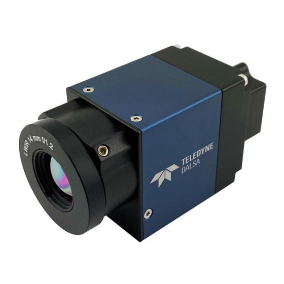
Calibir GXM640
Dalsa Calibir GXM640 Manuals
Manuals and User Guides for Dalsa Calibir GXM640. We have
1
Dalsa Calibir GXM640 manual available for free PDF download: User Manual
Dalsa Calibir GXM640 User Manual (150 pages)
Brand:
Dalsa
| Category:
IP Camera
| Size: 6 MB
Table of Contents
Table of Contents
3
Figures
7
Tables
8
Calibir Gxm640 Overview
9
Description
9
Key Features
9
Teledyne DALSA Development Software
10
Model Part Numbers
10
Calibir GXM640 Part Numbers
10
Table 1: Teledyne DALSA Development Software
10
Export Controls
11
Gxm640 Specifications
12
Table 2: Calibir GXM640 Series Specifications
12
Table 3: Calibir GXM640 NETD and Scene Range Specifications (at Ambient Temperature 25°C)
12
Gxm640 Emi, Shock and Vibration Certifications
13
Table 4: GXM 640 EMI, Shock and Vibration Certifications
13
Gige Vision Interface
14
Gige Vision Sapera Application Description
14
Figure 1: Gige Application Architecture
14
Gige Network Adapter Overview
15
PAUSE Frame Support
15
Computer Requirements for Calibir Gxm640
15
Host PC System
15
Software Requirements
16
Ethernet Switch Requirements for Calibir GXM640
17
Ethernet to Fiber-Optic Interface Requirements
18
Introduction to Microbolometers
19
Emissivity
20
Table 5: Emissivity Values for Common Materials
21
Quick Start Guide
22
Connecting the Calibir Gxm640 Gige Vision Camera
22
Calibir GXM640 Power Specifications
22
Steps for Camera Startup
22
Table 6: Calibir GXM640 Power Specifications
22
Calibir GXM640 Connectors
23
Figure 2: Calibir GXM640- Rear View
23
Preventing Operational Faults Due to ESD
24
Calibir IP Configuration Sequence
25
Camera Connection Setup
26
Displaying Images
27
Table 7: Bit Range for 16-Bit Image Display
28
Table 8: Image Display Using Different 8-Bit Ranges
28
Controlling Calibir Using the Sapera Lt Api
30
Features and Configuration Options
32
Heat Sinks
33
Adjusting the Lens Focus
33
Figure 3: Lens Lockdown Screws
33
Led Indicators
34
Calibir GXM640 LED States
34
Figure 4: Calibir GXM640 LED Startup Sequence
34
Table 9: Calibir GXM640 LED States
34
Fixed Pattern Noise Correction
35
Target Mode
35
Saving Fixed Pattern Noise Calibration
36
Performing Manual FPN Correction with External Shutter
36
Figure 5: FPN Compensation Mode
36
Figure 6: Performing FPN Correction
36
Figure 7: Faulty FPN Calibration
37
FPN Correction Using Triggered Acquisition
38
Automatic FPN Calibration
39
Related Gige Vision Features
39
Overlays
40
Related Gige Vision Features
41
Figure 8: Overlays
41
False Color Mapping
42
Related Gige Vision Features
42
Figure 9: Fire Color Map
42
Figure 10: Fire Color Map Range Overlay
42
Metadata
43
Related Gige Vision Features
45
Pixel Polarity
46
Related Gige Vision Features
46
Figure 11: Pixel Polarity
46
Defective Pixel Correction
47
Figure 12: Defective Pixel Map
47
Related Gige Vision Features
48
Figure 13: File Access Control
48
Median Filter
49
Related Gige Vision Features
49
Figure 14: Median Filter
49
Contrast Enhancement
50
Contrast Mode
50
Figure 15: Contrast Enhancement Mapping 16-Bit to 8-Bit
50
Figure 16: Dynamic Adaptive Image Enhancement
51
Table 10: Image Enhancement Dynamic Adaptive Contrast Examples
52
Figure 17: Contrast Enhancement Maximum Gain
53
Figure 18: Fixed Adaptive Image Enhancement
54
Figure 19: Fixed Adaptive Brightness Setting
55
Figure 20: Fixed Adaptive Brightness Setting Example
55
Table 11: Sample 16-Bit Image
56
Table 12: Static Contrast Mode Example
57
Table 13: Maximum Gain off Example
58
Table 14: Maximum Gain Setting Examples
58
Related Gige Vision Features
59
Table 15: Maximum Gain Setting 0.5 Example
59
Camera Synchronization
60
Slave Configuration with External Input Frame Trigger
61
Slave Configuration with PTP Trigger
61
Master Configuration with Output Pulses
62
Related Gige Vision Features
62
External Trigger
63
Sensor Readout Alignment Mode
65
Figure 21: External Trigger Wave Diagram: Free-Running
66
Related Gige Vision Features
67
Figure 22: External Trigger Wave Diagram: Frame-On-Demand
67
Precision Time Protocol
68
Hardware Considerations
68
PTP Synchronization
68
PTP Configuration Features
69
Related Gige Vision Features
69
Internal Test Pattern Generator
70
Calibir Test Patterns
70
Figure 23: Horizontal Ramp Test Pattern
70
Figure 24: Vertical Ramp Test Pattern
70
Figure 25: Diagonal Ramp Test Pattern
70
Related Gige Vision Features
71
Temperature Sensors
71
Figure 26: File Access Control Dialog
71
Error Log File
72
Related Gige Vision Features
72
Figure 27: File Access Control Dialog
72
Operational Reference
73
Using a Calibir Gxm640 Camera with Sapera Api
73
Network and Computer Overview
73
Installing Sapera LT
74
Camera Firmware Updates
74
Firmware Via Linux or Third Party Tools
74
Gige Server Verification
75
Gige Server Status
75
Figure 28: Gige Server Tray Icon
75
Figure 29: Gige Pop-Up Menu
75
Table 16: Gige Server Tray Icon States
75
Optimizing the Network Adapter Used with Calibir
76
Quick Test with Camexpert (Windows)
76
Figure 30: Gige Vision Device Status
76
About the Device User ID
77
Figure 31: Sapera Camexpert
77
Using Camexpert with Calibir Cameras
78
Table 17: Camexpert Display Pane Control Buttons
78
Figure 32: Sapera Camexpert GUI Layout
79
Camera Information Category
81
Camera Information Feature Descriptions
81
Figure 33: Camexpert Camera Information Category
81
Table 18: Camera Information Feature Descriptions
81
Power-Up Configuration Dialog
84
Figure 34: Power-Up Configuration Dialog
84
Image Format Controls Category
85
Image Format Controls Feature Descriptions
85
Figure 35: Camexpert Image Format Controls
85
Table 19: Image Format Controls Feature Descriptions
85
Fpn Correction Category
87
Figure 36: Camexpert FPN Correction Category
87
FPN Correction Feature Descriptions
88
Table 20: Image Processing Feature Descriptions
88
Contrast / Brightness Category
90
Figure 37: Camexpert Contrast / Brightness Category
90
Contrast / Brightness Feature Descriptions
91
Table 21: Contrast / Brightness Feature Descriptions
91
Image Processing Category
92
Figure 38: Camexpert Image Processing Category
92
Image Processing Feature Descriptions
93
Table 22: Image Processing Feature Descriptions
93
Overlay Control Category
95
Overlay Feature Descriptions
95
Figure 39: Camexpert Overlay Category
95
Table 23: Overlay Feature Descriptions
95
Acquisition Control Category
97
Figure 40: Camexpert Acquisition Control
97
Acquisition Control Feature Descriptions
98
Table 24: Acquisition Control Feature Descriptions
98
Features that Cannot be Changed During a Transfer
99
Trigger Control Features Category
100
Trigger Controls Feature Descriptions
100
Figure 41: Camexpert Trigger Control Features Category
100
Table 25: Trigger Control Controls Feature Descriptions
100
Examples Using Timestamp Modulo Event for Acquisitions
102
I/O Controls Category
106
I/O Controls Feature Descriptions
106
Figure 42: Camexpert I/O Controls Category
106
Table 26: I/O Controls Feature Descriptions
106
Event Control Category
108
Figure 43: Camexpert Event Control Category
108
Event Control Feature Descriptions
109
Table 27: Event Control Feature Descriptions
109
Overview of Precision Time Protocol Mode (IEEE 1588)
115
User Set Control Category
117
User Set Control Feature Descriptions
117
Figure 44: Camexpert User Set Control Category
117
Table 28: User Set Control Feature Descriptions
117
Metadata Controls Category
118
Metadata Controls Feature Descriptions
118
Figure 45: Camexpert Metadata Controls
118
Table 29: Metadata Controls Feature Descriptions
118
Gige Vision Transport Layer Category
119
Figure 46: Camexpert Gige Vision Transport Layer Category
119
Table 30: Gige Vision Transport Layer Feature Descriptions
120
Gige Vision Host Control Category
122
File Access Control Category
122
Figure 47: Camexpert File Access Control Category
122
Table 31: File Access Control Feature Descriptions
123
Figure 48: Camexpert File Access Control Category
124
Technical Specifications
125
Mechanical Specifications
125
Calibir GXM640 with M25 Lens Mount
125
Figure 49: Calibir GXM640 with M25 Lens Mount (MM Units)
125
Additional Notes on Calibir Identification and Mechanical
126
Connectors
126
10-Pin I/O Connector Details
126
Table 32: Samtec 10-Pin Connector Pin Assignment
126
Input Signal Electrical Specifications
127
Power over Ethernet (Poe) Support
131
Output Signals Electrical Specifications
131
Ec & Fcc Declarations of Conformity
136
Additional Reference Information
137
I/O Mating Connector Sources
137
Cable Assembly G3-AIOC-BLUNT2M
138
Figure 50: Cable Assembly G3-AIOC-BLUNT2M
138
Figure 51: Cable Assembly G3-AIOC-BLUNT2M Mechanical Drawing
138
Cable Assembly G3-AIOC-BRKOUT2M
139
Figure 52: Cable Assembly G3-AIOC-BRKOUT2M
139
Figure 53: Cable Assembly G3-AIOC-BRKOUT2M Mechanical Drawing
139
Ruggedized Rj45 Ethernet Cables
140
Figure 54: Ruggedized RJ45 Ethernet Cable with Thumbscrews
140
Sensor Handling Instructions
141
Cleaning the Sensor Window
141
Electrostatic Discharge and the Sensor
141
Troubleshooting
142
Overview
142
Quick Recovery Guide
142
General Troubleshooting for Calibir Gxm640
144
Error Log File
144
Power Failure During a Firmware Update-Now What
144
Power Supply Problems
144
Camera Is Functional, but Image Has no Contents
144
Calibir Gxm640 Troubleshooting
144
Gige Server Status
144
Table 33: Gige Server Tray Icon States
144
Problem Type Summary
145
Acquisition Error Without Timeout Messages
147
Figure 55: Random Bad Data or Noise Example
147
Cabling and Communication Problems
148
Verifying Network Parameters
149
Contact Information
150
Sales Information
150
Technical Support
150
Advertisement
Advertisement
Related Products
Dalsa CALIBIR 640 GigE
Dalsa Calibir 640 AS
Teledyne DALSA Calibir 640 Core
Dalsa Calibir 640 AB
Dalsa G3-GM10-M0800
Dalsa G3-GM10-M0801
Dalsa G3-GC10-C0640IF
Dalsa G3-GC10-C1450
Dalsa G3-GC10-C1941
Dalsa G3-GC11-C1920IF
Dalsa Categories
Digital Camera
Security Camera
Security Sensors
Media Converter
Machine Vision Systems
More Dalsa Manuals
Login
Sign In
OR
Sign in with Facebook
Sign in with Google
Upload manual
Upload from disk
Upload from URL