Daikin EKVDX50A2VEB Manuals
Manuals and User Guides for Daikin EKVDX50A2VEB. We have 4 Daikin EKVDX50A2VEB manuals available for free PDF download: Service Manual, Installer And User Manual, Installation And Operation Manual

Daikin EKVDX50A2VEB Service Manual (216 pages)
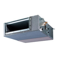
VRV system air conditioner
Brand: Daikin
|
Category: Air Conditioner
|
Size: 61 MB
Advertisement
Daikin EKVDX50A2VEB Installer And User Manual (96 pages)
VRV system air conditioner
Brand: Daikin
|
Category: Air Conditioner
|
Size: 4 MB
Table of Contents
Daikin EKVDX50A2VEB Service Manual (104 pages)
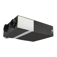
VRV System Air Conditioner
Brand: Daikin
|
Category: Air Conditioner
|
Size: 15 MB
Table of Contents
Advertisement

Daikin EKVDX50A2VEB Installation And Operation Manual (28 pages)
VRV system air conditioner
Brand: Daikin
|
Category: Air Conditioner
|
Size: 3 MB
Table of Contents
Advertisement