Sign In
Upload
Manuals
Brands
Curtis Instruments Manuals
Controller
MultiMode 1243 Generation 2
Curtis Instruments MultiMode 1243 Generation 2 Manuals
Manuals and User Guides for Curtis Instruments MultiMode 1243 Generation 2. We have
1
Curtis Instruments MultiMode 1243 Generation 2 manual available for free PDF download: Manual
Curtis Instruments MultiMode 1243 Generation 2 Manual (90 pages)
Motor Controller
Brand:
Curtis Instruments
| Category:
Controller
| Size: 0 MB
Table of Contents
Table of Contents
2
1 Overview
8
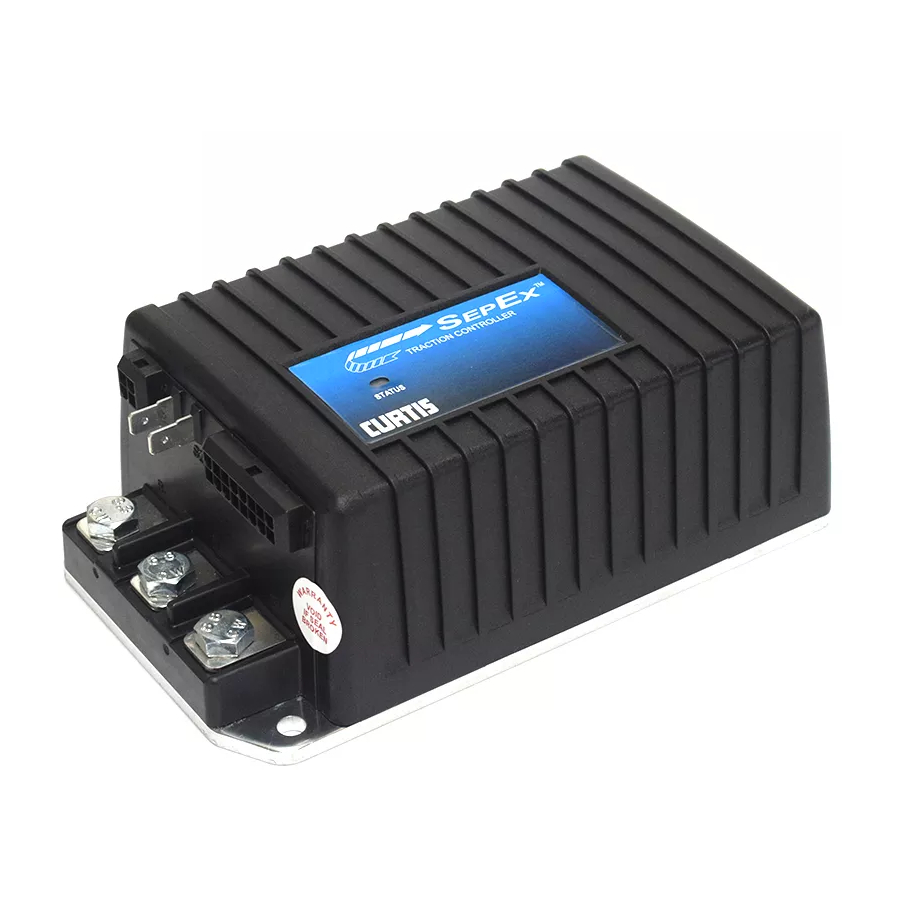
FIG . 1: Curtis 1243 GEN 2 Electronic Motor Controller
8
2 Installation and Wiring
11
Mounting the Controller
11
FIG . 2: Mounting Dimensions, Curtis 1243 GEN 2 Controller
11
Connections: Low Current
13
Connections: High Current
13
Wiring: Controller
14
FIG . 3: Basic Wiring Configuration, Curtis 1243 GEN 2 Controller
14
Wiring: Throttle
16
5Kω-0, 2-Wire Potentiometer Throttle ("Type 1")
17
FIG . 4: Wiring for 5Kω-0 Throttle ("Type 1")
17
Fig. 5 Wiring for 20K Ω Potentiometer Used as a Wigwag-Style Throttle ("Type 1")
17
And Electronic Throttles ("Type 2")
18
Fig. 6 Wiring for 0-5V Throttles ("Type 2")
18
Fig. 7 Wiring for Current Source Throttle ("Type 2")
19
Fig. 8 Wiring for 3-Wire Potentiometer Throttle ("Type 2")
19
0-5Kω, 2-Wire Potentiometer Throttle ("Type 3")
20
Fig. 9 Wiring for Curtis ET-XXX Electronic Throttle ("Type 2")
20
Wigwag 0-5V and 3-Wire Pot Throttles
21
Wiring: Fault Outputs
21
Fig. 10 Wiring for 0-5K Ω Throttle ("Type 3")
21
Wiring: Spyglass Display
22
FIG . 11: Wiring for Fault Outputs
22
FIG . 12: Wiring for Curtis Spyglass Display
22
Wiring: Emergency Reverse
23
Wiring: Emergency Reverse Check
23
Wiring: Auxiliary Driver
23
Contactor, Switches, and Other Hardware
24
Table 2 MODE SELECTION
25
3 Programmable Parameters
26
Battery Parameter
28
Battery Voltage
28
Acceleration Parameters
28
Drive Current Limit, M1-M4
28
Acceleration Rate, M1-M4
28
Quick Start
28
Current Ratio
29
Braking Parameters
30
Braking Current Limit, M1-M4
30
Deceleration Rate, M1-M4
30
Throttle Deceleration Rate
30
Restraint, M1-M4
30
Braking Rate, M1-M4
31
Braking Current Limit at 300 Amps
31
Taper Rate
32
Variable Braking
32
Interlock Braking Parameters
33
Interlock Braking Rate
33
Max. Forward Regen
33
Max. Reverse Regen
33
Min. Forward Regen
34
Min. Reverse Regen
34
Max Load Volts
34
Min Load Volts
34
Electromagnetic Brake Parameters
35
Aux Type
35
EM Brake PWM
35
Aux Delay
35
Interlock Brake Delay
35
14: Electromagnetic Brake Parameters, in the Context of the Four Delay Parameters
36
Speed Parameters
38
Max. Forward Speed, M1-M4
38
Max. Reverse Speed, M1-M4
38
Creep Speed
38
Load Compensation
38
Throttle Parameters
39
Throttle Type
39
Throttle Deadband
39
Table 4 PROGRAMMABLE THROTTLE TYPES
39
Fig. 15 Effect of Adjusting the Throttle Deadband Parameter
40
Throttle Max
41
FIG . 16: Effect of Adjusting the Throttle Max Parameter
41
Throttle Map
43
Throttle Maps for Controller with Maximum Speed Set at 100% and Creep Speed Set at 0
43
Throttle Maps for Controller with Maximum Speed Set at 100% and Creep Speed Set at 10
44
FIG . 19: Throttle Maps for Controller
44
Pot Low Fault
45
Field Parameters
45
Min. Field Current Limit
45
Max. Field Current Limit
45
Field Map Start
45
Field Map
46
FIG . 20: Field Current Relative to Armature Current
46
Field Check
47
Main Contactor Parameters
47
Main Contactor Interlock
47
Main Contactor Open Delay
47
Main Contactor Diagnostics
47
Sequencing Fault Parameters
48
Anti-Tiedown
48
High Pedal Disable (HPD)
48
Static Return to off (SRO)
49
Sequencing Delay
49
Emergency Reverse Parameters
50
Emergency Reverse Current Limit
50
Emergency Reverse Check
50
Emergency Reverse Direction Interlock
50
Motor Protection Parameters
51
Warm Speed
51
Motor Warm Resistance
51
Motor Hot Resistance
51
Motor Resistance Compensation
51
Hourmeter Parameters
52
Adjust Hours High
52
Adjust Hours Middle
52
Adjust Hours Low
52
Set Total Hours
52
Set Traction Hours
53
Total Service Hours
53
Traction Service Hours
53
Total Disable Hours
53
Traction Disable Hours
53
Traction Fault Speed
54
Service Total
54
Service Traction
54
Hourmeter Type
55
Pump Meter
55
Battery Discharge Indicator (BDI) Parameters
56
Full Voltage
56
Empty Voltage
56
Reset Voltage
56
Battery Adjust
57
BDI Disable
57
BDI Limit Speed
57
Fault Code Parameters
58
Fault Code
58
BDI Lockout
58
Controller Cloning
59
4 Installation Checkout
60
5 Vehicle Performance Adjustment
62
Major Tuning
62
Tuning the Active Throttle Range
62
Tuning the Controller to the Motor
65
Setting the Unloaded Vehicle Top Speed
67
Equalizing Loaded and Unloaded Vehicle Speed
68
Fine Tuning
69
Response to Reduced Throttle
69
Response to Increased Throttle
70
Smoothness of Direction Transitions
70
Ramp Climbing
71
6 Programmer Menus
72
GEN 2 Program Menu
72
GEN 2 Monitor Menu
76
GEN 2 System Faults Menu
77
7 Diagnostics and Troubleshooting
78
Programmer Diagnostics
78
Spyglass Diagnostics
78
Table 7 TROUBLESHOOTING CHART
79
FIG . 21: Curtis 840 Spyglass, 3-LED and 6-LED Models
80
Status LED Diagnostics
81
Table 8 STATUS LED FAULT CODES
81
Fault Output LED Diagnostics
82
Table 9 FAULT CATEGORY CODES
82
8 Controller Maintenance
83
Cleaning
83
Diagnostic History
83
Electromagnetic Compatibility (EMC
84
Curtis 1311 Handheld Programmer
87
APPENDIX A Electromagnetic Compatibility (EMC)
89
APPENDIX B 1311 Programmer Operation
89
Programmable Parameters Index
89
APPENDIX C Programmable Parameters Index
90
Specifications
90
Advertisement
Advertisement
Related Products
Curtis Instruments 1232
Curtis Instruments 1234
Curtis Instruments 1238
Curtis Instruments 1236
Curtis Instruments MultiMode 1230
Curtis Instruments 1212
Curtis Instruments 1212P
Curtis Instruments 1351
Curtis Instruments 1313
Curtis Instruments AC F4-A
Curtis Instruments Categories
Controller
Battery Charger
Motherboard
Touch Panel
I/O Systems
More Curtis Instruments Manuals
Login
Sign In
OR
Sign in with Facebook
Sign in with Google
Upload manual
Upload from disk
Upload from URL