Sign In
Upload
Manuals
Brands
ComNav Manuals
GPS
Vector G2
ComNav Vector G2 Manuals
Manuals and User Guides for ComNav Vector G2. We have
3
ComNav Vector G2 manuals available for free PDF download: Installation & Operation Manual, Installation And Operation Manual
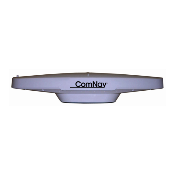
ComNav Vector G2 Installation & Operation Manual (92 pages)
Satellite Compasses Third Generation
Brand:
ComNav
| Category:
Compass
| Size: 5 MB
Table of Contents
Welcome
3
Warranty Notice
3
General Notice
3
Special Note
3
Document History
4
About this Manual
5
Manual Format
5
Table of Contents
7
List of Figures
10
List of Tables
11
Figure 1 - Typical NMEA 2000 G2 System Setup
15
Overview
15
Figure 2 - Typical NMEA 0183 G2 System Setup
16
Installation
20
Tools Required
20
Power Supply
20
Environmental Considerations
20
GNSS Reception Considerations
22
Figure 3 - Choose a Mounting Location
22
Figure 4 - Clear View Required for the Compass
22
Figure 5 - Mast Pole Blocked G2G2B Skyview (View from Top)
22
Radiobeacon Reception Considerations
23
Figure 6 - Mounting Distance to Large Metallic Surface
23
Location & Orientation
25
Figure 7 - Heading & Pitch Installation (Viewed from Above). Heading Bias Is 0° at this Orientation
25
Figure 8 - Heading & Roll Installation (Viewed from Above). Heading Bias Is 90° at this Orientation
26
Mounting
27
Figure 9 - Surface Mount Bracket Assembly
27
Figure 10 -Surface Mount Hole Measurements
28
Figure 11 - Surface Mount Bracket Assembly
28
Figure 12 - Assembled Surface Mount (Example)
29
Alignment
30
Wiring for NMEA 0183 System
30
Figure 13 - Long-Sight Alignment
30
Cables & Extensions
31
Cable Colour Codes
31
Power Input
31
Table 1 - Cable Colour Code
31
Serial Port Settings
32
Signal Grounds
32
Commander P2 or Admiral P3
33
Interfacing to a Comnav Autopilot
33
Table 2 - Commander P2 Connection Details
33
5001 System
34
Interfacing to a Navigator G2 Display System
34
Other Comnav Autopilot Systems
34
Figure 14 - Typical Wiring Diagram of a G2 System with Autopilot and Compass Display
35
D Connector Pinouts
36
Figure 15 - DE9 & DB25 Pin Numbering
36
Interfacing to a PC
36
PC COM Ports
36
DB25 Connectors
37
DE9 Connectors
37
Table 3 - PC COM Port (DE9) to G2'S RS-232 Port a
37
Table 4 - PC COM Port (DB25) to G2'S RS-232 Port 1
37
Figure 16 - Typical Wiring with a PC for G2 Control & Display
38
Using a G2 with a PC Navigation Program
38
Using a PC for G2 Control & Display
38
Figure 17 - Typical Wiring with a PC Based Navigation Program
39
Figure 18 - G2 with G3 Displays in an IMO G2 System
41
Use a G2 with the CAN-Bus Based G3 Display in IMO Installation
41
Wiring for NMEA 2000 System
42
Table 5 - Connect G2 to CAN Bus
42
Operation
45
Understanding How the G2 Works
45
Automatic & Continuous Operation
45
Acquisition Time
45
GPS and GLONASS
45
Determining Heading
46
Determining Position
46
Differential Corrections
46
Determining Speed and Other Navigation Information
47
Moving Base Station RTK
47
Supplemental Sensors
48
Operation in NMEA 0183 Environment
48
Output Ports
48
NMEA 0183 Output
50
Output Data Formats
50
Table 6 - Default NMEA Output Sentences Configuration
50
Proprietary Output
51
Baud Rate
51
Electrical Interface
51
Alarm Output
51
Audible Alarm Output
51
Table 7 - Default Proprietary Output Sentences Configuration
51
ISO 22090-3 Compliant NMEA 0183 Alarm Output
52
Table 8 - Alert Conditions
52
Table 9 - Alarm Handling Sentences
52
Operate in NMEA 2000 Environment
53
NMEA 2000 Data Output
53
Table 10 - List of Data Pgns and Default Update Rates
53
Changing the Configuration
54
Making Changes
54
Using a Terminal Program
54
Using a G3 Compass Display
55
Using a Navigator G2
55
Customising & Fine-Tuning the Configuration
55
Figure 19 - Setup Tera Term to Add a 100Ms Pause between Command Lines in a File
55
Smoothing Output Data with Time Constants
55
Changing the Time Constants
56
Table 11 - Smoothing Time Constants
56
Baud Rates & Data Bandwidth
57
DGPS Source
57
Table 12 - Time Constant Formulae
57
Care & Maintenance
60
Fuse Replacement
60
General Precautions
60
Periodic Checks
60
Protection of Wires and Cabling
60
Repair
60
Appendix 1 Specifications
62
DGPS Beacon Receiver (G2B Only)
62
GPS Receiver
62
Table 13 - GNSS Receiver Specifications
62
Power
63
System Interface
63
Table 14 - DGPS Beacon Receiver Specifications
63
Table 15 - System Interface Specifications
63
Table 16 - Power Specifications
63
Mechanical
64
Table 17 - Mechanical Specifications
64
Comnav Proprietary NMEA 0183 Sentences Descriptions
65
Appendix 2
65
NMEA 0183 Configuration Commands
66
Appendix 3
66
Table 18 - Commands for the NMEA Output Sentences
67
Table 19 - Commands for the Proprietary Output Sentences
67
Table 20 - Commands for the Smoothing Time Constants
67
Table 21 - Commands for Output Biases and Port Baud Rates
68
Table 22 - Commands for Status & Configuration
68
Table 23 - Commands for G2B Beacon Configuration
68
Table 24 - G2B Beacon Configuration Command Details
69
Configure Beacon Stations for G2B
70
Change the Beacon Scanning Mode
70
Create And/Or Modify Channel Map Table
70
Enter and Exit the Beacon Configuration Mode
70
Send a Configuration Command to the Beacon
70
Appendix 4
70
Change the Scanning Mode
71
Figure 20 - G2B Beacon Configuration Interface Screenshot
71
A Beacon Configuration Example
72
Retrofit G2/G2B to Vector G2/G2B
73
Table 25 - Vector G2/G2B Color Code When Used with G Series G2/G2B
73
Appendix 5
73
Appendices
62
Wheelmark Compliance Certificate
74
License Agreement
77
Warranty Information
80
Index
86
User Notes & Settings
90
User Settings
90
Table 26 - User Settings (NMEA 0183 Ports)
90
Table 27 - User Settings (Alignment & Operational)
91
Notes
92
Advertisement
ComNav Vector G2 Installation & Operation Manual (64 pages)
GPS Compass Display
Brand:
ComNav
| Category:
GPS
| Size: 1 MB
Table of Contents
Welcome
3
Document History
4
Table of Contents
5
List of Figures
7
List of Tables
7
Overview of the Navigator G2
11
Figure 1 - Vector G2 System Connections
11
Vector Series GPS Compass
12
Display Head
12
Figure 2 - Vector G2 GPS Compass
12
Figure 3 - Navigator G2 Display Head
12
Distribution Unit
13
Figure 4 - Distribution Unit
13
About this Manual
14
Typefaces, Common Phrases & Terms
14
Manual Format
14
Installation
17
Technical Requirements
17
Caution
17
Power Supply
17
Special Tools
17
Electrical Connections
18
Connector Termination
18
Figure 5 - Distribution Unit Connector Blocks
18
Figure 6 - Terminal Connection - Step 1
19
Figure 7 - Terminal Connection - Step 2
19
Terminal Strip Labels
20
Figure 8 - Terminal Connection Silk Screen Labels
20
Vector G2 Terminals
21
Table 1 - Vector G2 Wiring and Connections
21
Figure 9 - Vector G2 Power Connection - Always on or Switched
22
Display Head Terminals (#1 and #2)
23
Table 2 - Display Head Wiring and Connection
23
NMEA Output Terminal
24
Table 3 - External NMEA, 1-Pps, and Alarm Wiring
24
Ship Power Bus Terminal
25
Post Check
25
Power up Test
25
Figure 10 - Ship Power Connection
25
Basic Operation
29
Power On/Off
29
Figure 11 - Introductory Screen
29
Display Controls
30
Color Display Backlight and Day/Night Adjustment
30
Figure 12 - Color Control Head Backlight and Day/Night Adjust
30
Monochrome Display Contrast and Backlight Adjustment
31
Figure 13 - Monochrome Display Head Contrast and Backlight Adjust
31
Normal Usage
32
Figure 14 - Navigator G2 Display Head Displays and Buttons
32
Display Pages
33
Figure 15 - Graphical Navigation Page Description
33
Figure 16 - Text Navigation Page Description
34
Figure 17 - Position Navigation Page Description
34
Information Pages
35
Table 4 - Navigation Page Fields Descriptions
35
Figure 18 - Heading Information Page Description
36
Table 5 - Heading Information Page Fields Descriptions
36
Figure 19 - GPS Status Information Page Description
37
Table 6 - GPS Status Fields Descriptions
37
Figure 20 - GPS Satellite Information Page Description
38
Figure 21 - Parameter Setup Page - Button Descriptions
39
Parameter Setup Pages
39
Figure 22 - NMEA Message Rate Page
40
Figure 23 - Binary/Differential Message Rate Page
40
Figure 24 - Smoothing Filters and Aids Page
41
Figure 25 - Pitch/Roll Page
41
Care & Maintenance
45
Cleaning and Appearance
45
Protection of Wires and Cabling
45
Periodic Checks
45
Fuse Replacement
45
Appendix 1
49
Troubleshooting
49
Appendix 2
50
Wiring Reference for Comnav Standard Cables
50
Appendix 3
53
Wiring Termination in the Distribution Unit
53
Figure 26 - Cable Jacket Removal
53
Figure 27 - Cable Shield Removal
54
Figure 28 - Wire Insulation Removal
54
Appendix 4
55
General Specifications
55
Figure 29 - Distribution Unit Dimensions
55
Table 7 - Display Head General Specification
55
Table 8 - Distribution Unit General Specification
55
Warranty Information
59
User Notes
63
User Notes
64
Table 9 - User Notes
64
ComNav Vector G2 Installation And Operation Manual (32 pages)
GPS Compasses (Second Generation)
Brand:
ComNav
| Category:
Compass
| Size: 0 MB
Table of Contents
Document History
2
Standard Cables
4
Serial Ports
6
Interfacing to a Comnav Autopilot
8
Normal Operation
15
Changing the Configuration
19
Using Hyperterminal
20
User Notes & Settings
31
User Settings
31
Advertisement
Advertisement
Related Products
ComNav Vector G2B
ComNav VECTOR G1
ComNav G7
ComNav G3
ComNav Navigator G2
ComNav Categories
Autopilot System
Receiver
Marine Equipment
Computer Hardware
Remote Control
More ComNav Manuals
Login
Sign In
OR
Sign in with Facebook
Sign in with Google
Upload manual
Upload from disk
Upload from URL