Sign In
Upload
Manuals
Brands
ComNav Manuals
Marine Equipment
Commander P2VS
ComNav Commander P2VS Manuals
Manuals and User Guides for ComNav Commander P2VS. We have
1
ComNav Commander P2VS manual available for free PDF download: Installation & Operation Manual
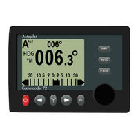
ComNav Commander P2VS Installation & Operation Manual (224 pages)
Advanced Autopilot Systems
Brand:
ComNav
| Category:
Marine Equipment
| Size: 11 MB
Table of Contents
Welcome
3
Warranty Notice
3
Document History
5
About this Manual
6
Table of Contents
8
List of Figures
15
List of Tables
17
How Autopilots Work
20
Manual Steering
20
An Autopilot System
21
Figure 1 - Basic Autopilot System
21
Autopilot Operation
22
Maintaining a Heading: AUTO Mode
22
Changing Heading
23
Figure 2 - Heading Change in AUTO Mode
23
Wind and Current Effects
24
Following a Track: NAV Mode
24
Following a Track: AUTO/ALC Mode
25
Power Steer: "Drive by Wire
25
More Information (for the Technically Inquisitive)
25
Figure 3 - Commander P2 System Block Diagram
28
Control Head
29
Figure 4 - Control Heads
29
Figure 5 - the Commander P2 SPU (with Wiring Cover Removed)
30
Signal Processor Unit
30
Compasses
31
Vector G2 and G2B GPS Compasses
31
Figure 6 - Vector G2 GPS Compass
31
Navigator G2 GPS Compasses Display
32
Figure 7 - Navigator G2 Display Head
32
Figure 8 - Navigator G2 Distribution Unit
32
Fluxgate Compasses
33
Figure 9 - Fluxgate Compass
33
Heading Rate Stabilizer
34
Figure 10 - Heading Rate Stabilizer
34
Magnetic Compass Sensor
35
Magnetic Compasses
35
Figure 11 - Magnetic Compass Sensor
35
Figure 12 - Externally Gimballed Magnetic Compass with Binnacle
35
45° Compass Transducer
36
Tri-Axis Rate Gyro Compass
36
Other Compasses
36
Figure 13 - 45° Compass Transducer
36
Figure 14 - Tri-Axis Rate Gyro Compass
36
Rudder Follower Units & Wind Sensors
37
Standard Rotary Rudder Follower Unit & Rudder Linkage
37
Heavy Duty Rotary Rudder Follower Unit
37
Figure 15 - Standard Rotary RFU
37
Figure 16 - Heavy Duty Rotary RFU
37
Linear Rudder Follower Unit
38
Twin-Fin Wind Transducer
38
Auxiliary Controllers
38
Figure 17 - Linear RFU
38
Figure 18 - Twin-Fin Wind Transducer
38
CR-203 Remote
39
Figure 19 - CR-203 Handheld Remote
39
Figure 20 - TS-203 Fixed Remote
40
Remote
40
Other Controls & Indicators
41
NFU Jog Steering Control
41
Rudder Angle Indicator (RAI)
41
Figure 21 - NFU Jog Steering Control
41
Figure 22 - External Rudder Angle Indicator (76 MM Model)
41
Control Head Mounting & Cover Kits
42
Figure 23 - Control Head Mounts & Cover
42
Rudder Drives and Interfaces
43
CT7 Thruster Interface
43
Figure 24 - CT7 Interface
43
Other Drive Boxes
44
Figure 25 - Drive Boxes to Meet All Needs
44
Pumps & Drives
45
Figure 26 - Hydraulic Pump & Solenoid Value
45
Figure 27 - Cable Drives
45
Other Equipment
45
System Overview
28
Installation
48
Basic Requirements
48
Steering System
48
Power Supply
48
Special Tools
48
Fasteners
48
Control Head
49
Electrical Connection
49
Signal Processor Unit
49
Compasses
50
Compass Deviation
50
Common Installation Considerations
50
Magnetic Compass and Sensor
52
Electrical Connection
52
Fluxgate Compass
53
Electrical Connection
53
Figure 28 - Fluxgate Compass Mounting
53
Heading Rate Stabilizer
54
Electrical Connection
54
45° Compass Transducer
54
Tri-Axis Rate Gyro Compass
54
Electrical Connection
55
Rudder Follower Unit
56
Rotary Rudder Follower Unit
56
Electrical Connection
57
Heavy Duty Rotary Rudder Follower Unit
57
Figure 29 - RFU Linkage Geometry
57
Linear Rudder Follower Unit
58
Figure 30 - Typical Arrangement of Linear RFU on an Outboard's Steering Cylinder
58
Figure 31 - Band Clamp and Plastic Brackets
59
Figure 32 - Installed Arrangement of Brackets
59
Electrical Connection
60
Figure 33 - Fasteners, Stainless Bracket Arrangement
60
Other Equipment
61
Wiring the System
62
Signal Processor Unit
62
Connectors on the SPU
62
Figure 34 - Removal of the SPU Wiring Cover
62
Figure 35 - SPU Connector Wiring Label
62
Table 1 - SPU Connector Ratings
63
Table 2 - Recommended Minimum Wire Gauges
63
Wire Sizes
63
Power Supply
64
Figure 36 - Typical Power Connection to SPU
64
Drive Box Power Supply
65
Figure 37 - Reducing Supply Voltage Losses
65
Figure 38 - Typical Battery Connection to Drive Boxes
65
Power Supply Extension
65
Input & Output Connections
66
Auxiliary Controller(S)
66
Control Head
66
Figure 39 - Wiring Connections for Control Head, Handheld Remotes, and Fixed Remotes
66
Figure 40 - Wiring Connections for Jog Controls
67
NFU Jog Steering Controls
67
Compasses
68
Figure 41 - Wiring Connections for Magnetic Sensor, Fluxgate Compass or HRS
68
Figure 42 - Wiring Connections for 45° Compass Transducer
69
Figure 43 - Wiring Connections for Tri-Axis Rate Gyro Compass
69
Figure 44 - Wiring Connections for Twin-Fin Wind Transducer
70
Wind Transducer
70
Figure 45 - Wind Transducer with NX2 Wind Data Instrument
71
Figure 46 - Wind Transducer with Classic Nexus or NX2 Network Server
71
Figure 47 - Wiring Connections for Rfus
72
Figure 48 - Wiring Connections for Rudder Angle Indicators
72
Rudder Angle Indicators
72
Rudder Follower Unit
72
Drive Outputs
73
Figure 49 - Wiring Connections for Reversing DC Motors
73
Figure 50 - Wiring Connections for Linear Actuators or Mechanical Rotary Drives
73
Linear Actuators or Mechanical Rotary Drives
73
Reversing DC Motor Hydraulic Systems
73
Shunt-Field Reversing Motors
73
Figure 51 - Wiring Connections for Shunt Field Reversing Motors
74
Figure 52 - Wiring Connections for Standard Four-Way Solenoid Valves
74
Standard Four-Way Solenoid-Activated Hydraulic Valves
74
Figure 53 - Wiring Connections for Constant Running Electric Pump
75
Figure 54 - Wiring Connections for Two-Speed Solenoid Valves
75
Two-Speed Solenoid Valves
75
A.C. Solenoids
76
Figure 55 - Wiring Connections for A.C. Solenoids
76
Figure 56 - Wiring Connections for Proportional Solenoid Valves
76
Proportional Solenoid Valves
76
Azimuth Drives, Surface Piercing Drives and Jet Drives
77
Figure 57 - Wiring Connections for Isolation Amplifiers
77
External Alarm Output
78
Figure 58 - External Alarm, Using SW'D B- Output
78
Figure 59 - External Alarm, Using SW'D B+ Output
78
Figure 60 - External Alarm, SW'D B- Output with Power Fail Option
79
Figure 61 - External Alarm, SW'D B+ Output with Power Fail Option
79
Speed Mode & Timing Outputs
80
Table 3 - Speed Mode & Timing Outputs
80
Navigation Data
81
Figure 62 - Typical NMEA 0183 Connections
81
RS-422 Electrical Interface
82
Signal Names
82
Table 4 - NMEA Signal Translation Guide
82
Figure 63 - Typical RS-422 Signals
83
Typical RS-422 Signals
83
RS-232 Electrical Signals
84
Status Leds
84
Other Connections
84
Comnav Network
84
Thruster Interface
84
Final Steps & Post-Installation Checks
85
Electrical Checks
85
Completing the Wiring
85
Setting up
88
Dockside Setup Menu
88
Figure 64 - Entering Dockside Setup
88
Figure 65 - Dockside Setup Menu
89
Reset
89
Vessel Type
89
Alarm O/P (Alarm Output)
90
Compass Setup
90
Drive Setup
90
Exit
90
Language
90
Table 5 - Vessel Types
90
Thrust MAX
90
Thrust MIN
90
Thrust Type
90
Configure Sys. (Configure System)
91
Setup Procedures
92
Vessel Type
92
Figure 66 - Set Vessel Type
92
Drive Setup
93
Compass Setup - Dockside
95
Analog Compass
95
Figure 67 - Set Compass Type in Compass Configuration Menu
95
Digital Compass
96
NAV 1 Port
96
NAV1 or NAV2 Port for General NMEA Compass
96
Bandwidth of an NMEA Compass Connection
97
Table 6 - Compass Types
99
Compass Setup - on the Water
100
Compensation for Magnetic Deviation
100
Magnetic Compass Sensor
100
Heading Rate Stabilizer
101
45° Compass
102
Comnav Fluxgate Compass and Other Fluxgate Compasses
102
Other NMEA Compasses
102
Tri-Axis Rate Gyro Compass
102
All Compass Types
103
Calibrating for Compass Offset
103
Magnetic Sensor
104
Compass Setup - Final Steps
104
Sea Trials
105
Sea Trial Procedure
105
Adjust Rudder Gain & Counter Rudder for Hi Speed
105
Adjust Rudder Gain, Counter Rudder, Turn Rate and Seastate for lo Speed
107
Adjust Seastate for Hi Speed
107
Adjust Speed Trip Point
107
Adjust Turn Rate for Hi Speed
107
Adjusting for Rougher Sea Conditions
108
Basic Operations
112
The Control Head's LCD Screen & Buttons
112
Figure 68 - Using the Control Head
112
Operating the System
114
Operating Modes - Overview
114
Mode Menus
114
Figure 69 - a Typical Menu
115
Rudder Angle Indicator (RAI)
116
Alarm Clear
116
Power on
117
Power off
117
Figure 70 - Power on Sequence
117
Figure 71 - Power off Sequence
117
STANDBY Mode
118
Figure 72 - Typical STANDBY Mode Screen
118
Standby Menu
119
Compass Source
119
Default Turn
119
Figure 73 - Standby Menu
119
Station Lock
119
Backlight Level
120
Compass Cal (Compass Calibration)
120
Contrast (Monochrome Head Only)
120
NMEA Hdg Type (NMEA Heading Type)
120
Figure 74 - Monochrome LCD: Normal & Reversed Display
121
Figure 75 - Colour LCD: B & C Colour Schemes
121
Graphics (Monochrome Head) or Display (Colour Head)
121
Battery
122
Fishzag Time
122
Watch Alarm
122
POWER STEER Mode
123
Figure 76 - Typical POWER STEER Mode Screen
123
Power Steer Menu
124
Auto/Nav Limits
124
Figure 77 - Power Steer Menu
124
P.str Limits (Power Steer Rudder Limits)
124
RAI Offset
124
AUTO Mode
125
Notes on AUTO Mode
125
Figure 78 - Typical AUTO Mode Screen
125
Auto Menu
126
Figure 79 - Auto Menu
126
Rudder Gain
126
Counter Rudder
127
Figure 80 - Guidelines for Setting Rudder Gain
127
Figure 81 - Guidelines for Setting Counter Rudder
127
Hi & lo Speed Counter Rudder
127
Hi & lo Speed Rudder Gain
127
Figure 82 - Hi (AUTO) and lo Speed Indicators (to Left of the Rudder Angle Indicator)
128
Parameter Set
128
Seastate
128
Turn Rate
128
ALC (Automatic Leeway Correction)
129
Figure 83 - Typical AUTO Mode Screen
129
Speed Source
129
Speed Trip Pt (Speed Trip Point)
129
Thruster Assist
129
Thruster Gain
129
Helm Delay
130
NAV Mode
131
Figure 84 - Typical NAV Mode Screen (Normal Display)
131
Figure 85 - Typical NAV Mode Highway Screen
132
NAV Highway Display
132
Notes on NAV Mode
132
Understanding NAV Mode
133
Checking the Navigation Data
133
Correction Methods
134
Table 7 - NAV Mode Correction Methods
134
CTS - Steering a Direct Bearing
135
Figure 86 - Steering with Correction Set to CTS
135
Figure 87 - Steering with Correction Set to XTE
136
XTE - Steering Quickly Back to a Track
136
Figure 88 - Response of Boat to a Large Cross-Track Error
137
Both - Steering Smoothly Back to a Track
138
Figure 89 - Steering with Correction Set to both
138
An Example of NAV Mode in Operation
139
Nav Menu
140
Figure 90 - Nav Menu
140
Nav Source
140
Waypoint Arrival
140
XTE Limit (Cross-Track Error Limit)
140
Correction
141
Max Correction
141
XTE Sense (Cross-Track Error Sense)
141
Dodge Turns
142
Figure 91 - a Dodge in Progress (in AUTO Mode)
142
Figure 92 - Boat Track During a Dodge Manoeuvre in AUTO Mode
142
Dodge Centre
143
Figure 93 - Holding at a Heading Part-Way through a Dodge Turn
143
Jog Steering Turns
144
Figure 94 - Typical Jog Control Activated Screen
144
Commander P2VS Operations
145
Cautions
145
P2-Equivalent Operation
147
Advanced Operations
151
WORK Mode
151
Automatic WORK Mode
151
Figure 95 - Typical WORK Mode Screen (Engaged)
151
Manual WORK Mode
152
Work Menu
153
Autotrim
153
Figure 96 - WORK Mode Menu
153
Rudder Bias
153
Rudder Scale (Rudder Scale Factor)
153
Work Mode State
153
Work Trip Pt. (Work Trip Point)
153
WIND Mode
154
Figure 97 - Typical WIND Mode Screen (Normal Display)
154
Changing Wind Angle
155
Low Wind Speeds
155
Tack & Gybe Inhibit
155
WIND-Points Mode
156
Changing Point of Sail
156
Figure 98 - Typical WIND-Points Mode Screen
156
Tack & Gybe Inhibit
156
Figure 100 - Outline Arrow Shows the Commanded Point of Sail
157
Figure 99 - Commanded Wind Angle of 90
157
Boundaries of the Points of Sail
158
Figure 101 - Points of Sail
158
Table 8 - Boundaries between Points of Sail
158
Figure 102 - Starting a Tack in WIND (Left) and WIND-Points (Right) Modes
159
Figure 103 - Wind Angle Limits to Start a Tack
159
Tacking
159
Figure 104 - Wind Angle Limits for Tacking
160
Figure 105 - Starting a Gybe in WIND (Left) and WIND-Points (Right) Modes
161
Figure 106 - Wind Angle Limits to Start a Gybe
161
Gybing
161
Figure 107 - Wind Angle Limits for Gybing
162
Wind Menu
163
Figure 108 - Wind Menu
163
Table 9 - Wind Source Selection
163
Wind Source
163
Beam Reach Def (Beam Reach Definition)
164
Broad Reach Def (Broad Reach Definition)
164
Close Haul Def (Close Haul Definition)
164
Close Reach Def (Close Reach Definition)
164
Gybe Hold Point (Gybe Hold Point Definition)
164
Preset Tack Angle
164
Wind Shift (Wind Shift Alarm)
164
Wind Shift Delay
164
Special Turns
165
Figure 109 - Typical Special Turn Query
165
Figure 110 - U-Turn Query
166
Figure 111 - U-Turn Boat Path
166
U-Turn
166
Circle Turn
167
Figure 112 - Circle Turn Query
167
Figure 113 - Circle Turn Boat Path
167
Figure 114 - M.O.B. Turn Query
168
Figure 115 - M.O.B. Turn Boat Path
168
M.O.B. - man Over-Board
168
Figure 116 - Fishzag Turn Query
169
Figure 117 - Fishzag Turn
169
Fishzag
169
Figure 118 - Pretack Turn Query
170
Pretack (Preset-Tack)
170
Multiple Control Heads & Auxiliary Controllers
171
Station Lock/Unlock
171
Figure 119 - Station Lock Icon on In-Command (Left) and Repeater Auxiliary Control Head (Right)
171
Watch Alarm & External Alarm
172
Configuring the Watch Alarm
172
Configuring the External Alarm
172
Figure 120 - External Alarm Configuration
172
Using the Watch Alarm
173
Figure 121 - External Alarm Type Configuration
173
Changing the Password
174
Figure 122 - New Password Pop-Up Window
174
Entering the Password
175
Figure 123 - Password Query Pop-Up Window
175
Care & Maintenance
179
Cleaning and Appearance
179
Periodic Checks
179
Electrical & Mechanical Checks
179
Hydraulic Checks
179
Air Trapped in the Hydraulic System
179
Manual Steering Operation
179
Fuse Replacement
180
Table 10 - Fuse Replacement Guide
180
Appendix 1 _______________________________________________________________________ 181 Interfacing to a PC
183
PC COM Ports
183
DB25 Connection
184
DE9 Connection
184
Figure 124 - Connection to a PC with a DE9-S Connector
184
Figure 125 - Connection to a PC with a DB25-S Connector
184
D Connector Pinouts
185
Figure 126 - DE9 & DB25 Pin Numbering
185
Appendix 2 _______________________________________________________________________ 185 NMEA 0183 Sentences Accepted and Transmitted by the Autopilot
187
Sentences Accepted
187
Table 11 - NMEA 0183 Sentences Accepted by the Commander P2
187
Sentence & Data Priority
188
Table 12 - NMEA Sentence Priority
189
Sentences Transmitted
190
Heading & Status
190
Heading Output
190
Status Output
191
Configuration Save & Restore
192
Table 13 - Configuration Save & Restore Sentences
195
Appendix 3 _______________________________________________________________________ 195 Error Messages
197
Critical Errors
197
Table 14 - Critical Error Messages
197
Severe Errors
198
Table 15 - Severe Error Messages
198
Table 16 - Warning Messages
199
Warnings
199
Appendix 4 _______________________________________________________________________ 199
201
Auxiliary Head / Remote Power on
201
Figure 127 - JP12 & JP13 in Factory Default Position (Left) and after Moving Shunts (Right)
201
Appendix 5 _______________________________________________________________________ 201
203
Diagnostic Leds
203
Table 17 - Diagnostic Leds
203
Appendix 6 _______________________________________________________________________ 203 Upgrading Firmware
205
Transferring the System Configuration & Parameters
205
Appendix 7 _______________________________________________________________________ 205
207
General Specifications
207
Table 18 - General Specifications
207
Compass Safe Distances
208
Table 19 - Compass Safe Distances
208
Warranty Information
209
Index
215
Settings & Notes
221
Default & User Settings
221
Table 20 - Default & User Settings
223
Notes
224
Advertisement
Advertisement
Related Products
ComNav Commander P2
ComNav P4 Remotes Series
ComNav P300
ComNav 11101
ComNav G7
ComNav SinoGNSS MarsLaser RTK
ComNav Categories
Autopilot System
Receiver
Marine Equipment
Compass
Transceiver
More ComNav Manuals
Login
Sign In
OR
Sign in with Facebook
Sign in with Google
Upload manual
Upload from disk
Upload from URL