Sign In
Upload
Manuals
Brands
Cirrus Logic Manuals
Amplifier
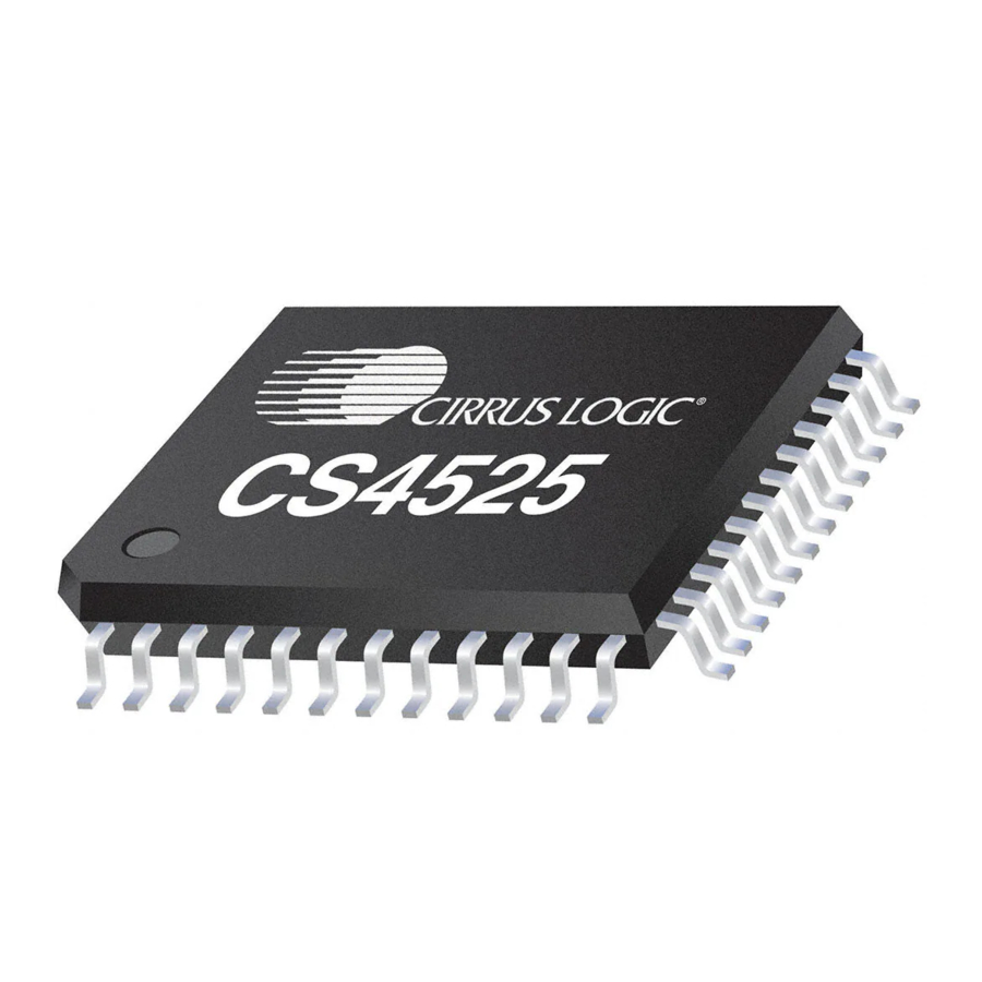
CS4525
Cirrus Logic CS4525 Manuals
Manuals and User Guides for Cirrus Logic CS4525. We have
2
Cirrus Logic CS4525 manuals available for free PDF download: Manual, Reference Design
Cirrus Logic CS4525 Manual (98 pages)
30 W Digital Audio Amplifier with Integrated ADC
Brand:
Cirrus Logic
| Category:
Amplifier
| Size: 1 MB
Table of Contents
Table of Contents
3
1 Pin Descriptions - Software Mode
8
2 Pin Descriptions - Hardware Mode
10
Digital I/O Pin Characteristics
12
Table 1. I/O Power Rails
12
3 Typical Connection Diagrams
13
Figure 1.Typical Connection Diagram - Software Mode
13
Figure 2.Typical Connection Diagram - Hardware Mode
14
4 Typical System Configuration Diagrams
15
Figure 3.Typical System Configuration 1
15
Figure 4.Typical System Configuration 2
15
Figure 5.Typical System Configuration 3
16
Figure 6.Typical System Configuration 4
17
5 Characteristics and Specifications
18
Figure 7.Serial Audio Input Port Timing
21
Figure 8.AUX Serial Port Interface Master Mode Timing
22
Figure 9.SYS_CLK Timing from Reset
23
Figure 10.PWM_SIGX Timing
23
Figure 11.Control Port Timing - I²C
24
6 Applications
26
Software Mode
26
System Clocking
26
SYS_CLK Input Clock Mode
26
Figure 12.Typical SYS_CLK Input Clocking Configuration
26
Crystal Oscillator Mode
27
Figure 13.Typical Crystal Oscillator Clocking Configuration
27
Power-Up and Power-Down
28
Recommended Power-Up Sequence
28
Recommended Power-Down Sequence
28
Input Source Selection
29
Digital Sound Processing
29
Figure 14.Digital Signal Flow
29
Channel Mixer
30
Digital Signal Processing High-Pass Filter
30
Pre-Scaler
30
Emphasis
31
Figure 15.De-Emphasis Filter
31
Table 2. Bass Shelving Filter Corner Frequencies
31
Tone Control
31
Table 3. Treble Shelving Filter Corner Frequencies
32
Figure 16.Bi-Quad Filter Architecture
33
Parametric EQ
33
Adaptive Loudness Compensation
34
Bass Management
35
Table 4. Bass Management Cross-Over Frequencies
35
Volume and Muting Control
36
6.1.4.10 Peak Signal Limiter
37
Figure 17.Peak Signal Detection & Limiting
37
6.1.4.11 Thermal Limiter
39
6.1.4.12 Thermal Foldback
40
Figure 18.Foldback Process
40
6.1.4.13 2-Way Crossover & Sensitivity Control
41
Table 5. 2-Way Cross-Over Frequencies
41
Auxiliary Serial Output
43
Table 6. Auxiliary Serial Port Data Output
43
Table 7. Nominal Switching Frequencies of the Auxiliary Serial Output
43
Serial Audio Delay & Warning Input Port
44
Serial Audio Delay Interface
44
External Warning Input Port
44
Powered PWM Outputs
45
Output Channel Configurations
45
PWM Popguard Transient Control
45
Table 8. PWM Power Output Configurations
45
Logic-Level PWM Outputs
46
Figure 19.Popguard Connection Diagram
46
Table 9. Typical Ramp Times for Various VP Voltages
46
Recommended PWM_SIG Power-Down Sequence for an External PWM Amplifier
47
Recommended PWM_SIG Power-Up Sequence for an External PWM Amplifier
47
Recommended PWM_SIG Power-Down Sequence for Headphone & Line-Out
48
Recommended PWM_SIG Power-Up Sequence for Headphone & Line-Out
48
PWM_SIG Logic-Level Output Configurations
49
Table 10. PWM Logic-Level Output Configurations
49
PWM Modulator Configuration
50
PWM Channel Delay
50
Figure 20.2-Channel Full-Bridge PWM Output Delay
50
Figure 21.3-Channel PWM Output Delay
50
PWM am Frequency Shift
51
Headphone Detection & Hardware Mute Input
51
Table 11. PWM Output Switching Rates and Quantization Levels
51
Table 12. Output of PWM_SIG Outputs
52
6.1.11 Interrupt Reporting
53
6.1.12 Automatic Power Stage Shut-Down
53
Hardware Mode
54
System Clocking
54
Power-Up and Power-Down
54
Recommended Power-Up Sequence
54
Figure 22.Typical SYS_CLK Input Clocking Configuration
54
Table 13. SYS_CLOCK Frequency Selection
54
Recommended Power-Down Sequence
55
Input Source Selection
55
PWM Channel Delay
55
Figure 23.Hardware Mode PWM Output Delay
55
Table 14. Input Source Selection
55
Table 15. Serial Audio Interface Format Selection
55
Digital Signal Flow
56
High-Pass Filter
56
Mute Control
56
Warning and Error Reporting
56
Figure 24.Hardware Mode Digital Signal Flow
56
Thermal Foldback
57
Figure 25.Foldback Process
57
Table 16. Thermal Foldback Enable Selection
57
Automatic Power Stage Shut-Down
58
PWM Modulators and Sample Rate Converters
58
Table 17. PWM Output Switching Rates and Quantization Levels
58
Output Filters
59
Half-Bridge Output Filter
59
Figure 26.Output Filter - Half-Bridge
59
Table 18. Low-Pass Filter Components - Half-Bridge
59
Table 19. DC-Blocking Capacitors Values - Half-Bridge
59
Full-Bridge Output Filter (Stereo or Parallel)
60
Figure 27.Output Filter - Full-Bridge
60
Table 20. Low-Pass Filter Components - Full-Bridge
60
Analog Inputs
61
Figure 28.Recommended Unity Gain Input Filter
61
Figure 29.Recommended 2 VRMS Input Filter
61
Serial Audio Interfaces
62
I²S Data Format
62
Left-Justified Data Format
62
Figure 30.I²S Serial Audio Formats
62
Figure 31.Left-Justified Serial Audio Formats
62
Right-Justified Data Format
63
Integrated VD Regulator
63
Figure 32.Right-Justified Serial Audio Formats
63
Table 21. Power Supply Configuration and Settings
63
I²C Control Port Description and Timing
64
Figure 33.Control Port Timing, I²C Write
64
Figure 34.Control Port Timing, I²C Read
64
7 Pcb Layout Considerations
65
Power Supply, Grounding
65
QFN Thermal Pad
65
8 Register Quick Reference
66
9 Register Descriptions
69
Clock Configuration (Address 01H)
69
SYS_CLK Output Enable (Ensysclk)
69
SYS_CLK Output Divider (Divsysclk)
69
Clock Frequency (Clkfreq[1:0])
69
Hp_Detect/Mute Pin Active Logic Level (Hp/Mutepol)
70
Hp_Detect/Mute Pin Mode (Hp/Mute)
70
Modulator Phase Shifting (Phaseshift)
70
AM Frequency Shifting (Freqshift)
70
Input Configuration (Address 02H)
71
Input Source Selection (ADC/SP)
71
ADC High-Pass Filter Enable (Enanhpf)
71
Serial Port Sample Rate (Sprate[1:0]) - Read Only
71
Input Serial Port Digital Interface Format (DIF [2:0])
71
AUX Port Configuration (Address 03H)
72
Enable Aux Serial Port (Enauxport)
72
Delay & Warning Port Configuration (Dlyportcfg[1:0])
72
Aux/Delay Serial Port Digital Interface Format (Auxi²S/Lj)
72
Aux Serial Port Right Channel Data Select (Rchdsel[1:0])
72
Aux Serial Port Left Channel Data Select (Lchdsel[1:0])
73
Output Configuration (Address 04H)
73
Output Configuration (Outputcfg[1:0])
73
PWM Signals Output Data Select (Pwmdsel[1:0])
73
Channel Delay Settings (Outputdly[3:0])
73
Foldback and Ramp Configuration (Address 05H)
74
Select VP Level (Selectvp)
74
Enable Thermal Foldback (Entherm)
74
Lock Foldback Adjust (Lockadj)
74
Foldback Attack Delay (Attackdly[1:0])
75
Enable Foldback Floor (Enfloor)
75
Ramp Speed (Rmpspd[1:0])
75
Mixer / Pre-Scale Configuration (Address 06H)
75
Pre-Scale Attenuation (Prescale[2:0])
75
Right Channel Mixer (Rchmix[1:0])
76
Left Channel Mixer (Lchmix[1:0])
76
Tone Configuration (Address 07H)
76
Emphasis Control (Deemph)
76
Adaptive Loudness Compensation Control (Loudness)
76
Digital Signal Processing High-Pass Filter (Endighpf)
77
Treble Corner Frequency (Trebfc[1:0])
77
Bass Corner Frequency (Bassfc[1:0])
77
Tone Control Enable (Entonectrl)
77
Tone Control (Address 08H)
78
Treble Gain Level (Treb[3:0])
78
Bass Gain Level (Bass[3:0])
78
Bass Manager/Parametric EQ Control (Address 09H)
78
Freeze Controls (Freeze)
78
Hi-Z PWM_SIG Outputs (Hizpsig)
79
Bass Cross-Over Frequency (Bassmgr[2:0])
79
Enable Channel B Parametric EQ (Enchbpeq)
79
Enable Channel a Parametric EQ (Enchapeq)
79
Volume and 2-Way Cross-Over Configuration (Address 55H)
80
Soft Ramp and Zero Cross Control (Szcmode[1:0])
80
Enable 50% Duty Cycle for Mute Condition (Mute50/50)
80
Auto-Mute (Automute)
80
Enable 2-Way Crossover (En2Way)
81
2-Way Cross-Over Frequency (2Wayfreq[2:0])
81
Channel a & B: 2-Way Sensitivity Control (Address 56H)
81
Channel a and Channel B Low-Pass Sensitivity Adjust (Lowpass[3:0])
81
Channel a and Channel B High-Pass Sensitivity Adjust (Highpass[3:0])
82
Master Volume Control (Address 57H)
82
Master Volume Control (Mvol[7:0])
82
Channel a and B Volume Control (Address 58H & 59H)
83
Channel X Volume Control (Chxvol[7:0])
83
Sub Channel Volume Control (Address 5Ah)
83
Sub Channel Volume Control (Subvol[7:0])
83
Mute/Invert Control (Address 5Bh)
84
ADC Invert Signal Polarity (Invadc)
84
Invert Channel PWM Signal Polarity (Invchx)
84
Invert Sub PWM Signal Polarity (Invsub)
84
ADC Channel Mute (Muteadc)
84
Independent Channel a & B Mute (Mutechx)
84
Sub Channel Mute (Mutesub)
85
Limiter Configuration 1 (Address 5Ch)
85
Maximum Threshold (Max[2:0])
85
Minimum Threshold (Min[2:0])
85
Peak Signal Limit All Channels (Limitall)
86
Peak Detect and Limiter Enable (Enlimiter)
86
Limiter Configuration 2 (Address 5Dh)
87
Limiter Release Rate (Rrate[5:0])
87
Limiter Configuration 3 (Address 5Eh)
87
Enable Thermal Limiter (Enthlim)
87
Limiter Attack Rate (Arate[5:0])
87
Power Control (Address 5Fh)
88
Automatic Power Stage Retry (Autoretry)
88
Enable Over-Current Protection (Enocprot)
88
Select VD Level (Selectvd)
88
Power down ADC (Pdnadc)
88
Power down PWM Power Output X (Pdnoutx)
88
Power down (Pdnall)
89
Interrupt (Address 60H)
89
SRC Lock State Transition Interrupt (Srclock)
89
ADC Overflow Interrupt (Adcovfl)
90
Channel Overflow Interrupt (Chovfl)
90
Amplifier Error Interrupt Bit (Amperr)
90
Mask for SRC State (Srclockm)
91
Mask for ADC Overflow (Adcovflm)
91
Mask for Channel X and Sub Overflow (Chovflm)
91
Mask for Amplifier Error (Amperrm)
92
Interrupt Status (Address 61H) - Read Only
92
SRC State Transition (Srclockst)
92
ADC Overflow (Adcovflst)
92
Sub Overflow (Subovflst)
92
Channel X Overflow (Chxovflst)
93
Ramp-Up Cycle Complete (Rampdone)
93
Amplifier Error Status (Address 62H) - Read Only
93
Over-Current Detected on Channel X (Overcurrx)
93
External Amplifier State (Extampst)
93
Under Voltage / Thermal Error State (UVTE[1:0])
94
Device I.D. and Revision (Address 63H) - Read Only
94
Device Identification (Deviceid[4:0])
94
Device Revision (Revid[2:0])
94
10 Parameter Definitions
95
11 References
95
12 Package Dimensions
96
13 Thermal Characteristics
97
Thermal Flag
97
14 Ordering Information
97
15 Revision History
98
Advertisement
Cirrus Logic CS4525 Reference Design (32 pages)
Brand:
Cirrus Logic
| Category:
Amplifier
| Size: 2 MB
Table of Contents
Table of Contents
2
1 System Overview
4
Power
4
CS4525 Digital Amplifier
4
CS8416 Digital Audio Receiver
4
System Clocking
4
External Data Headers
4
Analog Inputs
5
Speaker Outputs
5
PC Control
5
Stand-Alone Control
5
Figure 1.Speaker Terminal Configuration
5
External Power Stage Interface
6
2 Pc Software Control
7
CS4525 Main Controls Tab
7
Figure 2.CS4525 Main Controls Tab
7
CS4525 Aux & Filter Controls Tab
8
Figure 3.CS4525 Aux & Filter Controls Tab
8
S/PDIF Input Controls Tab
9
Figure 4.S/PDIF Input Controls Tab
9
Register Maps Tab
10
Figure 5.Register Maps Tab
10
Pre-Configured Script Files
11
Analog in
11
Optical SPDIF in
11
Coaxial SPDIF in
11
3 Stand-Alone Mode Control
12
4 Grounding and Power Supply Decoupling
12
Power Supply Decoupling
12
Electromagnetic Interference (EMI)
12
Suppression of EMI at the Source
13
5 System Connections & Jumpers
14
Table 1. System Connections
14
Table 2. On-Board Tactile Controls
14
Table 3. System Headers
14
6 Crd Schematics
15
Figure 6.CS4525 - Schematic
15
Figure 7.USB Microcontroller & Tactile Control - Schematic
16
Figure 8.Power & I/O Connections - Schematic
17
7 Crd Layout
18
Figure 9.Component Map
18
Figure 10.Top-Side Copper Layer
19
Figure 11.Inner Copper Layer 1
20
Figure 12.Inner Copper Layer 2
21
Figure 13.Bottom-Side Copper Layer
22
8 Performance Plots
23
Figure 14.Frequency Response
23
Figure 15.THD+N Vs. Power
24
Figure 16.THD+N Vs. Frequency
25
Figure 17.FFT at -60 Db Input
26
Figure 18.FFT at 0 Db Input
27
Figure 19.Inter-Modulation Distortion of 19 Khz + 20 Khz
28
9 Thermal De-Rating
29
Figure 20.Thermal De-Rating Curve for a Typical CRD4525-Q1
29
10 Electromagnetic Compliance (Emc) Performance
30
EMI Testing Procedures
30
Figure 21.Test Facility Setup
30
System Configuration
31
CRD4525-Q1 Test Results
31
Figure 22.Vertical Peak Scan Data for the CRD4525-Q1
31
Figure 23.Horizontal Peak Scan Data for the CRD4525-Q1
31
11 Revision History
32
Advertisement
Related Products
Cirrus Logic CRD3511-Q1
Cirrus Logic CS4265
Cirrus Logic CS493 Series
Cirrus Logic CS42528
Cirrus Logic CS42518-CQZ
Cirrus Logic CS44600
Cirrus Logic CS44600-CQZR
Cirrus Logic CS42516-DQZ
Cirrus Logic CS4244-CNZ
Cirrus Logic CS42518-CQ
Cirrus Logic Categories
Computer Hardware
Motherboard
Media Converter
Conference System
Controller
More Cirrus Logic Manuals
Login
Sign In
OR
Sign in with Facebook
Sign in with Google
Upload manual
Upload from disk
Upload from URL