Sign In
Upload
Manuals
Brands
Circutor Manuals
Measuring Instruments
CVM-B150
Circutor CVM-B150 Manuals
Manuals and User Guides for Circutor CVM-B150. We have
4
Circutor CVM-B150 manuals available for free PDF download: Instruction Manual
Circutor CVM-B150 Instruction Manual (330 pages)
Power Analyzer
Brand:
Circutor
| Category:
Measuring Instruments
| Size: 8 MB
Table of Contents
Safety Precautions
3
Disclaimer
3
Contents
4
Table of Contents
4
1 Revision Log
7
1 �- Verification UPON Reception
8
2 �- PRODUCT Description
8
3�- Unit Installation
10
3�1�- PRIOR Recommendations
10
3�2�- Installation
11
3�3�- UNIT Terminals
12
3�3�1�- Terminals on the Upper Face
12
3�3�2�- Terminals on the Lower Face
13
3�4�- Connection Diagrams
14
3�4�1�- Three-Phase Network Measurement with a 4-Wire Connection
14
3�4�2�- Three-Phase Network Measurement with a 3-Wire Connection
16
3�4�3�- Three-Phase Network Measurement with a 3-Wire Connection and Transfor
18
Mers with an ARON Connection
18
3�4�4�- Two-Phase Network Measurement with a 3-Wire Connection
19
3�4�5�- Single-Phase Network Measurement, Phase to Phase, with a 2-Wire Connec
20
Tion
20
3�4�6�- Single-Phase Network Measurement, Phase to Neutral, with a 2-Wire Connec
21
Tion
21
3�5�- Starting up the UNIT
22
4�- Operation
26
4�1�- Operating Principle
26
4 �2�- Measurement Parameters
27
4�3�- Keypad Functions
28
4�4�- Display
29
4�4�1�- Upper Area
29
4�4�2�- Lower Area
31
4�4�3�- Central Area
31
4�5�- Led INDICATORS
34
4�6�- Inputs
35
4�7�- Outputs
35
5�- Display and Configuration
36
5�1�-Measurement Display Menu
37
5 Display 1 Parameter
38
5�1�2�- Display 3 Parameters
63
5�1�3�- Display 4 Parameters
79
5�1�4�- Phasors
96
5�1�5�- STANDARD Phasors
97
Harmonics
98
5�1�7�- Integrated Functions
100
Expansion Modules
101
5�2�- Energy Closes Menu
103
5�2�1�- Active Energy Closes III of the TOTAL Tariff and of Reactive Energy
104
Of the TOTAL Tariff
104
5�3�- ALARM Menu
105
5�4�- Log Menu
107
5�4�1�- ALARM Log
108
5�4�2�- Event Log
109
5�5�- Information Menu
110
5�5�1�- System Information
111
5�5�2�- Integrated Functions
112
Expansion Modules
113
Circutor S�A
123
5�6�- Setup Menu
124
5�6�1�- Date and Time
126
5�6�2�- Time Zone
127
5�6�3�- Language
128
Access Key
129
5�6�5�- Measurement Connection Mode
130
5�6�6�- RATIO of Voltage Transformers
131
5�6�7�- RATIO of Current Transformers
133
5�6�8�- Installation Data
135
5�6�9�- Display of Variables
136
5�6�10�- Demand
137
5�6�11�- Energy CONSUMPTION COSTS
138
5�6�12�- Energy Generation COSTS
140
CO CONSUMPTION Emissions
141
CO Generation Emissions
143
Relay Digital OUTPUTS
144
5�6�16�- TRANSISTOR Digital OUTPUTS
152
5�6�17�- Digital INPUTS
161
5�6�18�- Integrated COMMUNICATIONS
167
5�6�19�- Parameter Reset
172
5�6�20�- User Interface
173
5�6�21�- Expansion Modules
175
6 �- Integrated COMMUNICATIONS
176
6�1�- Connections
176
6�2�- Modbus Protocol
177
6�2�1�- Example of MODBUS Query
178
6�3�- MODBUS Memory MAP
178
6�3�1�- Measurement Variables
178
6�3�2�- Current Energy Variables
180
6�3�3�- Maximum Demand Variables
184
6�3�4�- Voltage and Current Harmonics
185
6�3�5�- COST Variables
187
6�3�6�- Angle Variables
187
6�3�7�- UNIT Configuration Variables
188
6�3�8�- Other UNIT Variables
201
6�3�9�- Deleting Parameters
204
6�4�- Bacnet PROTOCOL
205
6�5�- Pics Map
206
7 �- Expansion Modules
209
7�1�- Installation
209
7�2�- Relay Digital INPUTS/OUTPUTS
213
7�2�1�- Connection Terminals
213
7�2�2�- Connection Diagrams
214
7�2�3�- Configuration
215
7�2�4�- Modbus Communications
219
7�3�- TRANSISTOR Digital INPUTS/OUTPUTS
227
7�3�1�- Connection Terminals
227
7�3�2�- Connection Diagrams
228
7�3�3�- Configuration
229
7�3�4�- Comunicaciones MODBUS
232
7�4�- Analogue INPUTS/OUTPUTS
243
7�4�1�- Connection Terminals
243
7�4�2�- Connection Diagrams
245
7�4�3�- Configuration
246
7�4�4�- Modbus Communications
254
7�5�- MODBUS/TCP Bridge COMMUNICATIONS Module
259
7�5�1�- Connection Terminals
259
7�5�2�- Leds
259
7�5�3�- Connection Diagram
260
7�5�4�- Configuration
260
7�5�5�- Modbus Communications
267
7�6�- Lonworks COMMUNICATIONS Module
268
7�6�1�- Connection Terminals
268
7�6�2�- Connection Diagram
268
7�6�3�- Configuration
269
7�6�4�- Modbus Communications
271
7�6�5�- LIST of Lonworks Logs
272
7�7�- Profibus COMMUNICATIONS Module
280
7�7�1�- Connection Terminals
280
7�7�2�- Leds
280
7�7�3�- Connection Diagram
281
7�7�4�- Configuration
282
7�7�5�- Modbus Communications
284
7�7�6�- Variables Profibus Gsd File
284
7�8�- MBUS COMMUNICATIONS Module
290
7�8�1�- Connection Terminals
290
7�8�2�- Connection Diagram
290
7�8�3�- Configuration
291
7�8�4�- Modbus Communications
293
7�8�5�- M-Bus Communications
294
7�9�- DATA Storage Module, Datalogger
296
7�9�1�- Connection Terminals
296
7�9�2�- Leds
296
7�9�3�- Connection Diagram
297
7�9�4�- Configuration
298
7�9�5�- Modbus Communications
303
7�10�- MODBUS/TCP Switch COMMUNICATIONS Module
304
7�10�1�- Connection Terminals
304
7�10�2�- Leds
304
7�10�3�- Connection Diagram
305
7�10�4�- Configuration
305
7�10�5�- Modbus Communications
309
8 �- Software Update
310
8�1�- UNIT Software Update
311
8�2�- Expansion Modules Update
311
9 �- Technical Features
313
10 �- Technical Features of Expansion Modules
317
10�1�- TRANSISTOR Digital INPUTS/OUTPUTS
317
10�2�- Relay Digital INPUTS/OUTPUTS
318
10�3�- Digital Analogue INPUTS/OUTPUTS
319
10�4�- MODBUS TCP (Bridge) COMMUNICATIONS
320
10�5�- Lonworks COMMUNICATIONS
321
10�6�- Profibus COMMUNICATIONS
322
10�7�- Mbus Communications
323
10�8�- DATA Storage, Datalogger
324
10�9�- MODBUS TCP (Switch) COMMUNICATIONS
325
11 �- Maintenance and Technical Service
327
12 �- Guarantee
327
13 �- Ce Certificate
328
Advertisement
Circutor CVM-B150 Instruction Manual (322 pages)
Power analyzer
Brand:
Circutor
| Category:
Measuring Instruments
| Size: 25 MB
Table of Contents
Safety Precautions
3
Disclaimer
3
Table of Contents
4
Contents
4
Revision Log
7
1�- Verification Upon Reception
8
2�- Product Description
8
3�- Device Installation
10
3�1�- Prior Recommendations
10
3�2�- Installation
11
3�3�- Device Terminals
12
3�3�1�- Terminals on the Upper Face
12
3�3�2�- Terminals on the Lower Face
13
3�4�- Connection Diagrams
14
3�4�1�- Three-Phase Network Measurement with a 4-Wire Connection
14
3�4�2�- Three-Phase Network Measurement with a 3-Wire Connection
16
Transformers
18
3�4�4�- Three-Phase Network Measurement with a 3-Wire Connection and Trans
19
Formers with an Aron Connection
19
3�4�5�- Two-Phase Network Measurement with a 3-Wire Connection
20
3�4�6�- Single-Phase Network Measurement, Phase to Phase, with a 2-Wire Connec
21
Tion
21
3�4�7�- Single-Phase Network Measurement, Phase to Neutral, with a 2-Wire Connec
22
Tion
22
3�5�- Starting up the Device
23
4�- Operation
29
4�1�- Operating Principle
29
4�2�- Measurement Parameters
30
4�3�- Keypad Functions
31
4�4�- Display
32
4�4�1�- Upper Area
32
4�4�2�- Lower Area
33
4�4�3�- Central Area
34
4�5�- Led Indicators
36
4�6�- Inputs
37
4�7�- Outputs
37
5�- Display and Configuration
38
5�1�-Measurement Display Menu
39
5�1�1�- Display 1 Parameter
40
5�1�2�- Display 3 Parameters
67
5�1�3�- Display 4 Parameters
85
5�1�4�- Phasors
103
5�1�5�- Standard Phasors
104
5�1�6�- Harmonics
105
5�1�7�- Integrated Functions
107
5�1�8�- Expansion Modules
108
5�2�- Energy Closes Menu
110
Total Tariff
111
5�3�- Alarm Menu
113
5�4�- Log Menu
115
5�4�1�- Alarm Log
116
5�4�2�- Event Log
118
5�5�- Information Menu
119
5�5�1�- System Information
120
5�5�2�- Integrated Functions
121
5�5�3�- Expansion Modules
122
5�5�4�- Circutor S�A
133
5�6�- Setup Menu
134
5�6�1�- Date and Time
137
5�6�2�- Time Zone
138
5�6�3�- Language
139
5�6�4�- Access Key
140
5�6�6�- Ratio of Voltage Transformers
142
5�6�7�- Ratio of Current Transformers
143
5�6�8�- Installation Data
145
5�6�9�- Display of Variables
146
5�6�10�- Demand
147
5�6�11�- Energy Consumption Costs
148
5�6�12�- Energy Generation Costs
149
5�6�13�- Co
150
Co Consumption Emissions
150
Consumption Emissions
150
5�6�14�- Co
151
Generation Emissions
151
5�6�15�- Relay Digital Outputs
153
5�6�16�- Transistor Digital Outputs
159
5�6�17�- Digital Inputs
164
5�6�18�- Integrated Communications
168
5�6�19�- Parameter Reset
171
5�6�20�- User Interface
173
5�6�21�- Expansion Modules
174
6�- Integrated Communications
175
6�1�- Connections
175
6�2�- Modbus Protocol
176
6�2�1�- Example of Modbus Query
177
6�3�- Modbus Memory Map
177
6�3�1�- Measurement Variables
177
6�3�2�- Current Energy Variables
179
6�3�3�- Maximum Demand Variables
183
6�3�4�- Voltage and Current Harmonics
184
6�3�5�- Cost Variables
186
6�3�6�- Angle Variables
186
6�3�7�- Device Configuration Variables
187
6�3�8�- Other Device Variables
200
6�3�9�- Deleting Parameters
203
6�4�- Bacnet PROTOCOL
204
6�5�- Pics Map
205
7�- Expansion Modules
208
7�1�- Installation
208
7�2�- Relay Digital Inputs/Outputs
212
7�2�1�- Connection Terminals
212
7�2�2�- Connection Diagrams
213
7�2�3�- Configuration
214
7�2�4�- Modbus Communications
218
7�3�- Transistor Digital Inputs/Outputs
225
7�3�1�- Connection Terminals
225
7�3�2�- Connection Diagrams
226
7�3�3�- Configuration
227
7�3�4�- Comunicaciones Modbus
229
7�4�- Analogue Inputs/Outputs
240
7�4�1�- Connection Terminals
240
7�4�2�- Connection Diagrams
242
7�4�3�- Configuration
243
7�4�4�- Modbus Communications
249
7�5�- Modbus/Tcp Bridge Communications Module
254
7�5�1�- Connection Terminals
254
7�5�2�- Leds
254
7�5�3�- Connection Diagram
255
7�5�4�- Configuration
255
7�5�5�- Modbus Communications
260
7�6�- Lonworks Communications Module
262
7�6�1�- Connection Terminals
262
7�6�2�- Connection Diagram
262
7�6�3�- Configuration
263
7�6�4�- Modbus Communications
265
7�6�5�- List of Lonworks Logs
265
7�7�- Profibus Communications Module
273
7�7�1�- Connection Terminals
273
7�7�2�- Leds
273
7�7�3�- Connection Diagram
274
7�7�4�- Configuration
275
7�7�5�- Variables Profibus Gsd File
276
7�8�- Mbus Communications Module
282
7�8�1�- Connection Terminals
282
7�8�2�- Connection Diagram
282
7�8�3�- Configuration
283
7�8�4�- Modbus Communications
285
7�8�5�- M-Bus Communications
285
7�9�- Data Storage Module, Datalogger
287
7�9�1�- Connection Terminals
287
7�9�2�- Leds
287
7�9�3�- Connection Diagram
288
7�9�4�- Configuration
289
7�9�5�- Modbus Communications
293
7�10�- Modbus/Tcp Switch Communications Module
294
7�10�1�- Connection Terminals
294
7�10�2�- Leds
294
7�10�3�- Connection Diagram
295
7�10�4�- Configuration
295
7�10�5�- Modbus Communications
299
8�- Software Update
300
8�1�- Device SOFTWARE UPDATE
301
8�2�- Expansion Modules Update
301
8�3�- Upgrading the Firmware of the Datalogger Module
302
9�- Technical Features
304
10�- Technical Features of Expansion Modules
308
10�1�- Transistor Digital Inputs/Outputs
308
10�2�- Relay Digital Inputs/Outputs
309
10�3�- Digital Analogue Inputs/Outputs
310
10�4�- MODBUS TCP (Bridge) COMMUNICATIONS
311
10�5�- Lonworks Communications
312
10�6�- Profibus Communications
313
10�7�- Mbus Communications
314
10�8�- Data Storage, Datalogger
315
10�9�- MODBUS TCP (Switch) COMMUNICATIONS
316
11�- Maintenance and Technical Service
318
12�- Guarantee
318
13�- Ce Certificate
319
Circutor CVM-B150 Instruction Manual (322 pages)
Power analyzer
Brand:
Circutor
| Category:
Measuring Instruments
| Size: 48 MB
Table of Contents
Safety Precautions
3
Disclaimer
3
Table of Contents
4
Contents
4
Revision Log
7
1�- Verification Upon Reception
8
2�- Product Description
8
3�- Device Installation
10
3�1�- Prior Recommendations
10
3�2�- Installation
10
3�3�- Device Terminals
11
3�3�1�- Terminals on the Upper Face
11
3�3�2�- Terminals on the Lower Face
12
3�4�- Connection Diagrams
13
3�4�1�- Three-Phase Network Measurement with a 4-Wire Connection
13
3�4�2�- Three-Phase Network Measurement with a 3-Wire Connection
15
3�4�3�- Three-Phase Network Measurement with a 3-Wire Connection and 3 Voltage Transform
17
Ers
17
Aron Connection
18
3�4�5�- Two-Phase Network Measurement with a 3-Wire Connection
19
3�4�6�- Single-Phase Network Measurement, Phase to Phase, with a 2-Wire Connection
20
3�4�7�- Single-Phase Network Measurement, Phase to Neutral, with a 2-Wire Connection
21
3�5�- Starting up the Device
22
4�- Operation
28
4�1�- Operating Principle
28
4�2�- Measurement Parameters
29
4�3�- Keypad Functions
30
4�4�- Display
31
4�4�1�- Upper Area
31
4�4�2�- Lower Area
32
4�4�3�- Central Area
33
4�5�- Led Indicators
35
4�6�- Inputs
36
4�7�- Outputs
36
5�- Display and Configuration
37
5�1�-Measurement Display Menu
38
5�1�1�- Display 1 Parameter
39
5�1�2�-Display 3 Parameters
66
5�1�3�-Display 4 Parameters
84
5�1�4�-Phasors
102
5�1�5�-Standard Phasors
103
5�1�6�-Harmonics
104
5�1�7�- Integrated Functions
106
5�1�8�-Expansion Modules
107
5�2�- Energy Closes Menu
109
5�3�- Alarm Menu
112
5�4�- Log Menu
114
5�4�1�- Alarm Log
115
5�4�2�- Event Log
117
5�5�- Information Menu
118
5�5�1�- System Information
119
5�5�2�- Integrated Functions
120
5�5�3�- Expansion Modules
121
5�5�4�- Circutor S�A�U
132
5�6�- Setup Menu
133
5�6�1�- Date and Time
136
5�6�2�- Time Zone
137
5�6�3�- Language
138
5�6�4�- Access Key
139
5�6�5�- Measurement Connection Mode
140
5�6�6�- Ratio of Voltage Transformers
141
5�6�7�- Ratio of Current Transformers
142
5�6�8�- Installation Data
144
5�6�9�- Display of Variables
145
5�6�10�- Demand
146
5�6�11�- Energy Consumption Costs
147
5�6�12�- Energy Generation Costs
148
5�6�13�- Co Consumption Emissions
149
5�6�14�- Co Generation Emissions
150
5�6�15�- Relay Digital Outputs
152
5�6�16�- Transistor Digital Outputs
158
5�6�17�- Digital Inputs
163
5�6�18�- Integrated Communications
167
5�6�19�- Parameter Reset
170
5�6�20�- User Interface
172
5�6�21�- Expansion Modules
173
6�- Integrated Communications
174
6�1�- Connections
174
6�2�- Modbus Protocol
175
6�2�1�- Example of Modbus Query
176
6�3�- Modbus Memory Map
176
6�3�1�- Measurement Variables
176
6�3�2�- Current Energy Variables
178
6�3�3�- Maximum Demand Variables
182
6�3�4�- Voltage and Current Harmonics
183
6�3�5�- Cost Variables
185
6�3�6�- Angle Variables
186
6�3�7�- Device Configuration Variables
186
6�3�8�- Other Device Variables
199
6�3�9�- Deleting Parameters
202
6�4�- Bacnet PROTOCOL
203
6�5�- Pics Map
204
7�- Expansion Modules
207
7�1�- Installation
207
7�2�- Relay Digital Inputs/Outputs
211
7�2�1�- Connection Terminals
211
7�2�2�- Connection Diagrams
212
7�2�3�- Configuration
213
7�2�4�- Modbus Communications
217
7�3�- Transistor Digital Inputs/Outputs
224
7�3�1�- Connection Terminals
224
7�3�2�- Connection Diagrams
225
7�3�3�- Configuration
226
7�3�4�- Comunicaciones Modbus
228
7�4�- Analogue Inputs/Outputs
239
7�4�1�- Connection Terminals
239
7�4�2�- Connection Diagrams
241
7�4�3�- Configuration
242
7�4�4�- Modbus Communications
248
7�5�- Modbus/Tcp Bridge Communications Module
253
7�5�1�- Connection Terminals
253
7�5�2�- Leds
253
7�5�3�- Connection Diagram
254
7�5�4�- Configuration
254
7�5�5�- Modbus Communications
259
7�6�- Lonworks Communications Module
261
7�6�1�- Connection Terminals
261
7�6�2�- Connection Diagram
261
7�6�3�- Configuration
262
7�6�4�- Modbus Communications
264
7�6�5�- List of Lonworks Logs
264
7�7�- Profibus Communications Module
272
7�7�1�- Connection Terminals
272
7�7�2�- Leds
272
7�7�3�- Connection Diagram
273
7�7�4�- Configuration
274
7�7�5�- Variables Profibus Gsd File
275
7�8�- Mbus Communications Module
281
7�8�1�- Connection Terminals
281
7�8�2�- Connection Diagram
281
7�8�3�- Configuration
282
7�8�4�- Modbus Communications
284
7�8�5�- M-Bus Communications
284
7�9�- Data Storage Module, Datalogger
286
7�9�1�- Connection Terminals
286
7�9�2�- Leds
286
7�9�3�- Connection Diagram
287
7�9�4�- Configuration
288
7�9�5�- Modbus Communications
292
7�10�- MODBUS/TCP Switch COMMUNICATIONS MODULE
293
7�10�1�- Connection Terminals
293
7�10�2�- Leds
293
7�10�3�- Connection Diagram
294
7�10�4�- Configuration
294
7�10�5�- Modbus Communications
298
8�- Software Update
299
8�1�- Device Software Update
300
8�2�- Expansion Modules Update
300
8�3�- Upgrading the Firmware of the Datalogger Module
301
9�- Technical Features
303
10�- Technical Features of Expansion Modules
307
10�1�- Transistor Digital Inputs/Outputs
307
10�2�- Relay Digital Inputs/Outputs
308
10�3�- Digital Analogue Inputs/Outputs
309
10�4�- MODBUS TCP (Bridge) COMMUNICATIONS
310
10�5�- Lonworks Communications
311
10�6�- Profibus Communications
312
10�7�- Mbus Communications
313
10�8�- Data Storage, Datalogger
314
10�9�- MODBUS TCP (Switch) COMMUNICATIONS
315
11�- Maintenance and Technical Service
318
12�- Guarantee
318
13�- Eu Declaration of Conformity
319
Advertisement
Circutor CVM-B150 Instruction Manual (18 pages)
Brand:
Circutor
| Category:
Measuring Instruments
| Size: 0 MB
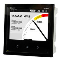
Table of Contents
Safety Precautions
3
Disclaimer
3
Table of Contents
4
Contents
4
Revision Log
5
1�- Introduction
6
2�- Xml Services
6
2�1�- /Services/User/Devices�Xml
7
2�2�- /Services/User/Deviceinfo�Xml?ID=Dispositivo
7
2�3�- /Services/User/Varinfo�Xml?Var=Dispositivo�Variable
8
2�4�- /Services/User/Values�Xml?Var=Dispositivo�Variable
9
2�5�-/Services/User/Forcevariables�Xml?ID=Dispositivo
10
2�6�-/Services/User/Records�Xml?Begin
11
2�7�-/Services/User/Events�Xml?Begin
14
2�8�-/Services/User/Recordseve�Xml?Begin
15
3�- Technical Service
17
4�- Guarantee
17
Advertisement
Related Products
Circutor CVM-B100
Circutor CVM-BDM
Circutor CVM-BDM-C420
Circutor CVM-BDM-420
Circutor CVM-BDM-C2
Circutor CVM-B150-ITF-HF
Circutor CVM-A1000
Circutor CVM-E3-MINI-MC-WiEth
Circutor CVM-E3-MINI-FLEX
Circutor CVM-D421
Circutor Categories
Measuring Instruments
Relays
Automobile Accessories
Battery Charger
Controller
More Circutor Manuals
Login
Sign In
OR
Sign in with Facebook
Sign in with Google
Upload manual
Upload from disk
Upload from URL