Sign In
Upload
Manuals
Brands
Carrier Manuals
Inverter
UG 15 Tier 4
Carrier UG 15 Tier 4 Manuals
Manuals and User Guides for Carrier UG 15 Tier 4. We have
1
Carrier UG 15 Tier 4 manual available for free PDF download: Operation And Service Manual
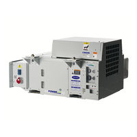
Carrier UG 15 Tier 4 Operation And Service Manual (45 pages)
Engine Emission System, Generator Sets
Brand:
Carrier
| Category:
Inverter
| Size: 9.45 MB
Table of Contents
Table of Contents
3
Paragraph Number
7
Safety Summary
7
General Safety Notices
7
Specific Warning and Caution Statements
7
Ash Handling
8
Important Information: Your Rights and Responsibilities
8
Your Right to Maintenance Information
8
Importance of Engine Maintenance
9
Introduction
9
Installation
9
Importance of Diesel Emission Control Strategy
9
Fuel and Oil Requirements
9
Fuel Requirements
9
Engine Oil Requirements
9
Figure Number
11
Description
11
Engine Emission System (Ees) Overview
11
Figure 3.1 Engine Emission System (EES) Components
11
Exhaust System Description
12
Diesel Oxidation Catalyst (DOC)
12
Diesel Particulate Filter (DPF)
12
Figure 3.2 Diesel Oxidation Catalyst (DOC)
12
Figure 3.3 Diesel Particulate Filter (DPF)
12
Fuel Injector (Doser) Description
13
Fuel Injector (Doser)
13
EES Fuel Pump and Filter
13
Figure 3.4 Doser
13
Figure 3.5 EES Fuel Pump
13
Air Control Valve (Acv) Description
14
Emissions Control Module (Ecm) Description
14
Figure 3.6 Air Control Valve (ACV)
14
Figure 3.7 Emissions Control Module (ECM)
14
Figure 3.8 Service Light
14
Sensors
15
Exhaust Inlet Temperature Sensor (ESEIT)
15
Filter Inlet Temperature Sensor (ESFIT)
15
Figure 3.9 ESEIT
15
Figure 3.10 ESFIT
15
Filter Outlet Temperature Sensor (ESFOT)
16
Back Pressure Sensor (ESFP)
16
Regeneration
16
Figure 3.11 ESFOT
16
Figure 3.12 Back Pressure Sensor (ESFP)
16
Table Number
17
System Specifications
17
Table 3-1 System Specifications
17
Ecm Service Tool
19
Overview and Initial Setup
19
Figure 4.1 ECM Service Tool
19
Figure 4.2 ECM CAN Adapter
19
Component Check
20
Air Control Valve (ACV)
20
Figure 4.3 ECM Service Tool - Connected
20
Injector (Doser)
21
Fuel Pump
21
Figure 4.4 ECM Service Tool - Component Check
21
Initiating a Manual Regeneration
22
Figure 4.5 ECM Service Tool - Manual Regeneration
22
Alarms
23
Figure 4.6 ECM Service Tool - Alarms
23
Figure 4.7 ECM Service Tool - Alarms Active
24
Figure 4.8 ECM Service Tool - Alarms Corrected
24
Sensor Readings
25
Figure 4.9 ECM Service Tool - Alarms Cleared
25
Figure 4.10 ECM Service Tool - Sensor Readings
25
Retrieving Data
26
Figure 4.11 ECM Service Tool - Retrieving Data
26
Programming the Ecm with New Software
27
Figure 4.12 ECM Service Tool - Software Update
27
Alarms and Troubleshooting
29
Alarms
29
Other Potential Failure Modes
31
Troubleshooting with the Ees Service Tool
32
Operation with 250 Hour Service Mode Alarm Active
32
Service
33
Engine Maintenance
33
Ees Maintenance
33
Service & Diagnostics
33
Dpf Manual Cleaning
33
Figure 6.1 Service Light
33
Table 6-1 EES Maintenance
33
Carb Registration and System Labeling
34
Figure 6.2 CARB Labels for DOC and DPF
34
Figure 6.3 CARB Label Placement Location
34
Schematics
35
Figure 7.1 Schematic
35
Parts
37
Table 8-1 Retrofit Kit #74-00324-00 for EES Field Installation
37
Table 8-2 Exhaust Kit #76-00955-00
37
Table 8-3 Air Control Valve (ACV) Kit #76-00956-00
38
Table 8-4 Coolant Kit #76-00957-00
38
Table 8-5 Voltage Kit #76-00958-00
39
Table 8-6 Fuel System Kit #76-00959-00
39
Table 8-7 Control Box Kit #76-00960-00
40
Eu Declaration of Conformity
41
Index
43
Advertisement
Advertisement
Related Products
Carrier 42QHE07D8SH
Carrier 42QHG007D8S
Carrier 42QTD012D8S-1
Carrier 42QTD018D8S-2
Carrier 42QTD024D8S
Carrier 42QSS012D8S-1
Carrier 42QSS018D8S-1
Carrier 42QZL018D8S-2
Carrier 42QZL024D8S-1
Carrier 42QFD048D8S
Carrier Categories
Air Conditioner
Heat Pump
Furnace
Thermostat
Chiller
More Carrier Manuals
Login
Sign In
OR
Sign in with Facebook
Sign in with Google
Upload manual
Upload from disk
Upload from URL