Sign In
Upload
Manuals
Brands
Canon Manuals
Plotter
iPF800 Series
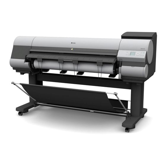
User Manuals: Canon iPF800 Series Large Format Printer
Manuals and User Guides for Canon iPF800 Series Large Format Printer. We have
2
Canon iPF800 Series Large Format Printer manuals available for free PDF download: Service Manual
Canon iPF800 Series Service Manual (376 pages)
Brand:
Canon
| Category:
Plotter
| Size: 12 MB
Table of Contents
Symbols Used
4
Symbol Description
4
Table of Contents
7
Chapter 1 Product Description
11
Product Overview
15
Product Overview
17
Features
23
Printhead
24
Ink Tank
24
Cutter
25
Roll Holder
25
Stand
26
Wheeled Output Stacker
26
Media Take-Up Unit
27
Hard Disk Drive
29
Consumables
30
Product Specifications
31
Product Specifications
32
Detailed Specifications
36
Print Speed and Direction
36
Interface Specifications
43
Names and Functions of Components
45
Front
45
Front
46
Rear
47
Rear
49
Rear
50
Top Cover (Inside)
51
Carriage
52
Ink Tank Cover (Inside)
52
Basic Operation
53
Operation Panel
53
Main Menu
54
Main Menu Settings
66
Main Menu
74
Main Menu
75
Main Menu Settings
86
Main Menu Settings
107
Basket Unit
138
Safety and Precautions
144
Safety Precautions
144
Moving Parts
144
Adhesion of Ink
145
Electric Parts
147
Other Precautions
148
Printhead
148
Ink Tank
149
Handling the Printer
150
Precautions When Servicing Printer
152
Notes on the Data Stored in the Printer
152
Confirming the Firmware Version
152
Precautions against Static Electricity
152
Precautions for Disassembly/Reassembly
152
Self-Diagnostic Feature
152
Disposing of the Lithium Battery
152
Chapter 2 Technical Reference
155
Basic Operation Outline
159
Printer Diagram
159
Printer Diagram
161
Printer Diagram
162
Print Signal Sequence
163
Print Driving
165
Firmware
167
Operation Sequence at Power-On
167
Operation Sequence at Power-Off
168
Print Control
169
Print Position Adjustment Function
176
Head Management
176
Printhead Overheating Protection Control
176
Pause between
176
Sleep Mode
176
Hard Disk Drive
176
White Raster Skip
176
Printer Mechanical System
178
Outline
178
Ink Passage
179
Overview of Ink Passage
179
Ink Tank Unit
180
Structure of Ink Tank Unit
180
Carriage Unit
182
Functions of Carriage Unit
182
Structure of Carriage Unit
183
Printhead
185
Structure of Printhead
185
Purge Unit
186
Functions of Purge Unit
186
Structure of Purge Unit
188
Maintenance Cartridge
190
Air Flow
191
Paper Path
192
Outline
192
Overview of Paper Path
192
Paper Path
193
Structure of Pick-Up/Feed Unit
193
Cutter Unit
196
Structure of Cutter Unit
196
Printer Electrical System
197
Outline
197
Overview
197
Overview
199
Main Controller
201
Main Controller PCB Components
201
Carriage Relay PCB
203
Carriage Relay PCB Components
203
Head Relay PCB
203
Head Relay PCB Components
203
Motor Driver
205
Media Take-Up PCB Components
205
Lower Roll Unit PCB Components
205
Maintenance Cartridge Relay PCB
205
Maintenance Cartridge Relay PCB Components
205
Power Supply
206
Power Supply Block Diagram
206
Detection Functions with Sensors
207
Sensors for Covers
207
Ink Passage System
208
Carriage System
210
Paper Path System
212
Media Take-Up Unit
214
Others
214
Chapter 3 Installation
215
Transporting the Printer
219
Transportation Procedure
223
Reinstalling the Printer
231
Chapter 4 DISASSEMBLY/REASSEMBLY
233
Service Parts
237
Disassembly/Reassembly
238
Points to Note on Disassembly and Reassembly
238
Note on Locations Prohibited from Disassembly
238
Moving the Carriage Manually
238
Units Requiring Draining of Ink
238
External Covers
240
Drive Unit
252
Cutter
254
Carriage Unit
256
Ink Tube Unit
260
Pick-Up/Feed Unit
263
Purge Unit
268
Waste Ink Collection Unit
269
Ink Tank Unit
279
Multi Sensor
281
Linear Encoder Sensor
284
Head Management Sensor
285
Pcbs
286
Opening the Cap/Moving the Wiper Unit
287
Opening and Closing Ink Supply Valves
288
Draining the Ink
289
Applying the Grease
290
Adjustment and Setup Items
293
Adjustment Item List
293
Procedure after Replacing the Carriage Unit or Multi Sensor
293
Procedure after Replacing the Feed Roller or Feed Roller Encoder
293
Procedure after Replacing the Head Management Sensor
293
Chapter 5 MAINTENANCE
295
Periodic Replacement Parts
299
Consumable Parts
299
Periodic Maintenance
300
Chapter 6 Troubleshooting
305
Outline
309
Outline of Troubleshooting
309
Location of Connectors and Pin Arrangement
309
Main Controller PCB
309
Carriage Relay PCB
319
Head Relay PCB
324
Version up
328
Firmware Update Tool
328
Service Tools
330
Tool List
330
Chapter 7 Service Mode
331
Service Mode Operation
335
Service Mode
335
Map of the Service Mode
336
Details of Service Mode
342
Sample Printout
352
Special Mode
356
Special Modes for Servicing
356
Chapter 8 Error Code
359
Outline
363
Warning Table
364
Warnings
364
Error Table
366
Errors
366
Sevice Call Table
373
Service Call Errors
373
Advertisement
Canon iPF800 Series Service Manual (320 pages)
Brand:
Canon
| Category:
Plotter
| Size: 11 MB
Table of Contents
Table of Contents
7
Chapter 1 PRODUCT DESCRIPTION
11
Product Overview
15
Features
19
Printhead
19
Ink Tank
19
Cutter
21
Roll Holder
21
Stand
22
Wheeled Output Stacker
22
Media Take-Up Unit
23
Hard Disk Drive
25
IEEE1394 (Firewire) Board
25
Consumables
26
Product Specifications
27
Detailed Specifications
29
Print Speed and Direction
29
Interface Specifications
36
Names and Functions of Components
37
Front
37
Front
39
Rear
40
Top Cover (Inside)
42
Carriage
43
Ink Tank Cover (Inside)
43
Basic Operation
44
Operation Panel
44
Main Menu
45
Main Menu
65
Basket Unit
85
Safety and Precautions
91
Safety Precautions
91
Moving Parts
91
Adhesion of Ink
92
Electric Parts
94
Other Precautions
95
Printhead
95
Ink Tank
96
Handling the Printer
97
Precautions When Servicing Printer
99
Notes on the Data Stored in the Printer
99
Confirming the Firmware Version
99
Precautions against Static Electricity
99
Self-Diagnostic Feature
99
Disposing of the Lithium Battery
99
Chapter 2 TECHNICAL REFERENCE
101
Basic Operation Outline
105
Printer Diagram
105
Printer Diagram
106
Print Signal Sequence
107
Print Driving
108
Firmware
110
Operation Sequence at Power-On
110
Operation Sequence at Power-Off
111
Print Control
112
Print Position Adjustment Function
119
Head Management
119
Printhead Overheating Protection Control
119
Pause between
119
White Raster Skip
119
Sleep Mode
119
Hard Disk Drive
119
Printer Mechanical System
121
Outline
121
Ink Passage
122
Overview of Ink Passage
122
Ink Tank Unit
123
Structure of Ink Tank Unit
123
Carriage Unit
125
Functions of Carriage Unit
125
Structure of Carriage Unit
126
Printhead
128
Structure of Printhead
128
Purge Unit
129
Functions of Purge Unit
129
Structure of Purge Unit
131
Maintenance Cartridge
133
Air Flow
134
Paper Path
135
Outline
135
Overview of Paper Path
135
Paper Path
136
Structure of Pick-Up/Feed Unit
136
Cutter Unit
139
Structure of Cutter Unit
139
Printer Electrical System
140
Outline
140
Overview
140
Overview
142
Main Controller
144
Main Controller PCB Components
144
Carriage Relay PCB
146
Carriage Relay PCB Components
146
Head Relay PCB
146
Head Relay PCB Components
146
Motor Driver
148
Media Take-Up PCB Components
148
Lower Roll Unit PCB Components
148
Maintenance Cartridge Relay PCB
148
Maintenance Cartridge Relay PCB Components
148
Power Supply
149
Power Supply Block Diagram
149
Detection Functions with Sensors
150
Sensors for Covers
150
Ink Passage System
151
Carriage System
153
Paper Path System
155
Media Take-Up Unit
157
Others
157
Chapter 3 INSTALLATION
159
Transporting the Printer
163
Reinstalling the Printer
175
Chapter 4 DISASSEMBLY/REASSEMBLY
177
Disassembly/Reassembly
177
Service Parts
181
Disassembly/Reassembly
182
Points to Note on Disassembly and Reassembly
182
Note on Locations Prohibited from Disassembly
182
Moving the Carriage Manually
182
Units Requiring Draining of Ink
182
External Covers
184
Drive Unit
196
Cutter
198
Carriage Unit
200
Ink Tube Unit
204
Pick-Up/Feed Unit
207
Purge Unit
212
Waste Ink Collection Unit
213
Ink Tank Unit
223
Multi Sensor
225
Linear Encoder Sensor
228
Head Management Sensor
229
Pcbs
230
Opening the Cap/Moving the Wiper Unit
231
Opening and Closing Ink Supply Valves
232
Draining the Ink
233
Applying the Grease
234
Adjustment and Setup Items
237
Adjustment Item List
237
Procedure after Replacing the Carriage Unit or Multi Sensor
237
Procedure after Replacing the Feed Roller or Feed Roller Encoder
237
Procedure after Replacing the Head Management Sensor
237
Chapter 5 MAINTENANCE
239
Periodic Replacement Parts
243
Consumable Parts
243
Periodic Maintenance
244
Chapter 6 Troubleshooting
249
Outline
253
Outline of Troubleshooting
253
Location of Connectors and Pin Arrangement
253
Main Controller PCB
253
Carriage Relay PCB
263
Head Relay PCB
268
Version up
272
Firmware Update Tool
272
Service Tools
273
Tool List
273
Chapter 7 SERVICE MODE
275
Service Mode
275
Service Mode Operation
279
Service Mode
279
Map of the Service Mode
280
Details of Service Mode
286
Sample Printout
296
Special Mode
300
Special Modes for Servicing
300
Chapter 8 ERROR CODE
303
Outline
307
Warning Table
308
Warnings
308
Error Table
310
Errors
310
Sevice Call Table
317
Service Call Errors
317
Advertisement
Related Products
Canon imagePROGRAF TM Series
Canon iPF8000 - imagePROGRAF Color Inkjet Printer
Canon iPF8000S - imagePROGRAF Color Inkjet Printer
Canon iPF8000 series
Canon imagePROGRAF iPF810
Canon imagePROGRAF iPF810 PRO
Canon imagePROGRAF iPF820 PRO
Canon imagePROGRAF iPF825 MFP Basic Guide No.1
Canon imagePROGRAF iPF8300
Canon imagePROGRAF iPF8300S
Canon Categories
Printer
Digital Camera
All in One Printer
Camcorder
Scanner
More Canon Manuals
Login
Sign In
OR
Sign in with Facebook
Sign in with Google
Upload manual
Upload from disk
Upload from URL