Sign In
Upload
Manuals
Brands
Burkert Manuals
Control Unit
Type 2002
Burkert Type 2002 Manuals
Manuals and User Guides for Burkert Type 2002. We have
7
Burkert Type 2002 manuals available for free PDF download: Operating Instructions Manual, Assembly Instructions Manual, Service Manual
Bürkert Type 2002 Operating Instructions Manual (94 pages)
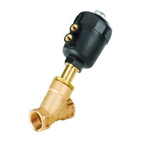
2/2-Way Angle Seat Valve, 3/2-Way Globe Valve
Brand:
Bürkert
| Category:
Control Unit
| Size: 5 MB
Table of Contents
English
3
Table of Contents
3
Operating Instructions
5
Symbols
5
Type
5
Authorized Use
6
Restrictions
6
Predictable Misuse
6
Basic Safety Instructions
7
Use In Zone 1/21, Explosion-Protected Area
8
General Information
8
Scope Of Supply
8
Contact Address
8
Warranty
9
Licences
9
Information On The Internet
9
Product Description
9
General Description
9
Properties
9
Intended Application Area
10
Structure And Function
11
Structure
11
Function
11
Technical Data
15
Inscription On The Rating Plate
15
Operating Conditions
15
General Technical Data
20
Assembly
21
Safety Instructions
21
Before Installation
21
Installation
22
Pneumatic Connection
24
Disassembly
25
Electrical Control
26
Controlling The Actuator
26
Maintenance, Troubleshooting
26
Safety Instructions
26
Maintenance Work
27
Malfunctions
27
Spare Parts
28
Replacement Part Sets
28
Repairs
31
Packaging And Transport
32
Disposal
32
Deutsch
33
Die Bedienungsanleitung
35
Darstellungsmittel
35
Bestimmungsgemässe Verwendung
36
Beschränkungen
36
Vorhersehbarer Fehlgebrauch
36
Grundlegende Sicherheitshinweise
37
Einsatz In Zone 1/21, Explosionsgeschützter Bereich
38
Allgemeine Hinweise
38
Lieferumfang
38
Kontaktadressen
38
Gewährleistung
39
Zulassungen
39
Informationen IM Internet
39
Produktbeschreibung
39
Allgemeine Beschreibung
39
Eigenschaften
39
Vorgesehener Einsatzbereich
40
Aufbau Und Funktion
41
Aufbau
41
Funktion
41
Technische Daten
45
Beschriftung Des Typenschildes
45
Betriebsbedingungen
45
Allgemeine Technische Daten
50
Montage
51
Sicherheitshinweise
51
Vor Dem Einbau
51
Einbau
52
Pneumatischer Anschluss
54
Demontage
55
Elektrische Ansteuerung
56
Ansteuerung Des Antriebs
56
Wartung, Fehlerbehebung
56
Sicherheitshinweise
56
Wartungsarbeiten
57
Störungen
57
Ersatzteile
58
Ersatzteilsätze
58
Instandhaltung
61
Verpackung, Transport
62
Entsorgung
62
Français
63
Les Instructions De Service
65
Moyens De Représentation
65
Limitations
66
Mauvaise Utilisation Prévisible
66
Utilisation Conforme
66
Consignes De Sécurité Fondamentales
67
Coordonnées De Contact
68
Remarques Générales
68
Utilisation En Zone 1/21, Protégée Contre Les Explosions
68
Étendue De La Livraison
68
Description Du Produit
69
Description Générale
69
Garantie Légale
69
Homologations
69
Informations Sur Internet
69
Propriétés
69
Utilisation Prévue
70
Fonction
71
Structure
71
Structure Et Mode De Fonctionnement
71
Caractéristiques Techniques
75
Légende De La Plaque Signalétique
75
Conditions D'exploitation
75
Caractéristiques Techniques Générales
80
Montage
81
Consignes De Sécurité
81
Avant Le Montage
81
Montage
82
Raccordement Pneumatique
84
Démontage
85
Commande De L'actionneur
86
Commande Électrique
86
Maintenance, Dépannage
86
Consignes De Sécurité
86
Travaux De Maintenance
87
Pannes
87
Pièces De Rechange
88
Jeux De Pièces De Rechange
88
Maintenance
91
Élimination
92
Advertisement
Burkert Type 2002 Operating Instructions Manual (87 pages)
2/2-Way Angle Seat Valve, 3/2-Way Globe Valve
Brand:
Burkert
| Category:
Control Unit
| Size: 1 MB
Table of Contents
English
3
Table of Contents
3
Operating Instructions
4
Symbols
4
Definition Of The Term "Device
4
Authorized Use
5
Basic Safety Instructions
5
Restrictions
5
Instructions For Use In Explosion Protected Area
6
(Ex Area)
6
Special Conditions
7
General Information
8
Product Description
8
Contact Addresses
8
Warranty
8
Information On The Internet
8
General Description
8
Properties
8
Structure And Function
9
Structure
9
Function
10
Technical Data
12
Conformity
12
Standards
12
Approvals
12
Type Label
12
Operating Conditions
13
General Technical Data
17
Assembly
18
Safety Instructions
18
Before Installation
19
Installation
19
Pneumatic Connection
21
Start-Up
23
Control Pressure
23
Flow Direction Above The Seat
23
Flow Direction Below The Seat
23
Disassembly
24
Maintenance, Troubleshooting
24
11.1. Safety Instructions
24
11.2. Maintenance Work
25
11.3. Malfunctions
25
Spare Parts
26
12.1. Replacement Part Sets
26
Repairs
29
Packaging, Transport, Storage
29
Deutsch
31
Begriffsdefinition Gerät
32
Darstellungsmittel
32
Die Bedienungsanleitung
32
Beschränkungen
33
Bestimmungsgemässe Verwendung
33
Grundlegende Sicherheitshinweise
33
Hinweise für den Einsatz IM Explosionsgeschützten (Ex-) Bereich
34
Besondere Bedingungen
35
Allgemeine Beschreibung
36
Allgemeine Hinweise
36
Eigenschaften
36
Gewährleistung
36
Informationen IM Internet
36
Kontaktadressen
36
Produktbeschreibung
36
Aufbau
37
Aufbau Und Funktion
37
Funktion
38
Konformität
40
Normen
40
Technische Daten
40
Typschild
40
Zulassungen
40
Betriebsbedingungen
41
Allgemeine Technische Daten
45
Montage
46
Sicherheitshinweise
46
Einbau
47
Vor Dem Einbau
47
Pneumatischer Anschluss
49
Anströmung Unter Sitz
51
Anströmung Über Sitz
51
Inbetriebnahme
51
Steuerdruck
51
11.1. Sicherheitshinweise
52
Demontage
52
Wartung, Fehlerbehebung
52
11.2. Wartungsarbeiten
53
11.3. Störungen
53
12.1. Ersatzteilsätze
54
Ersatzteile
54
Instandhaltung
57
Transport, Lagerung, Verpackung
57
Français
59
Définition Du Terme Appareil
60
Moyens De Représentation
60
À Propos De Ce Manuel
60
Consignes De Sécurité Fondamentales
61
Limitations
61
Utilisation Conforme
61
Consignes Pour L'utilisation Dans la Zone Protégée Contre Les Explosions
62
Conditions Particulières
63
Adresses
64
Description Du Produit
64
Description Générale
64
Garantie Légale
64
Informations Sur Internet
64
Propriétés
64
Remarques Générales
64
Structure
65
Structure Et Mode De Fonctionnement
65
Fonction
66
Caractéristiques Techniques
68
Conformité
68
Homologations
68
Normes
68
Plaque Signalétique
68
Conditions D'exploitation
69
Caractéristiques Techniques Générales
73
Consignes De Sécurité
74
Montage
74
Avant Le Montage
75
Montage
75
Raccordement Pneumatique
77
Arrivée Du Flux Au-Dessus Du Siège
78
Mise En Service
78
Pression De Commande
78
Arrivée Du Flux Sous Le Siège
79
Démontage
79
11.1. Consignes De Sécurité
80
11.2. Travaux De Maintenance
80
Maintenance, Dépannage
80
11.3. Pannes
81
12.1. Jeux De Pièces De Rechange
82
Pièces De Rechange
82
Maintenance
84
Transport, Stockage, Emballage
85
Burkert Type 2002 Assembly Instructions Manual (88 pages)
Stroke limitation / Min-, max. stroke limitation Hand wheel / Electrical position repeater
Brand:
Burkert
| Category:
Control Unit
| Size: 3 MB
Table of Contents
English
3
Table of Contents
3
The Manual
4
Symbols
4
Intended Use
5
Basic Safety Instructions
5
Type-Specific Safety And Warning Instructions
6
General Information
7
Scope Of Supply
7
Warranty Provisions
7
Product Designations And Manufacturers
7
Overview Of Models
8
Option Stroke Limitation, Simple Version
8
Option Min, Max. Stroke Limitation
8
Option Hand Wheel
9
Option Electrical Positioner Repeater
9
Control Air Connectors
10
Actuators D-50, E-63, F-80 And G-100, H-125
10
Actuators K-175 And L-225
10
Option: Maximum Stroke Limitation
11
Actuators D-50, E-63 And F-80
11
Actuators G-100, H-125
14
Actuators K-175, L225
14
Option: Min. /Max. Stroke Limitation
16
Actuators D-50, E-63 Und F-80
16
Actuators G-100, H-125
18
Actuators K-175, L-225
19
Option: Hand Wheel
21
Actuators D-50 Bis H-125
21
Actuators D-50 Bis F-80
23
Actuators G-100, H-125
25
Actuators K-175, L-225
27
Order Data
29
Options
29
Assembly Accessories
29
Option: Electrical Position Repeater
23
Deutsch
31
Darstellungsmittel
32
Die Anleitung
32
Bestimmungsgemässe Verwendung
33
Grundlegende Sicherheitshinweise
33
Typenspezifische Sicherheits- Und Warnhinweise
34
Allgemeine Hinweise
35
Lieferumfang
35
Gewährleistung
35
Produktbezeichnungen Und Hersteller
35
Typenübersicht
36
Option Hubbegrenzung, Einfachausführung
36
Option Min-, Max-Hubbegrenzung
36
Option Handrad
37
Option Elektrischer Stellungsrückmelder
37
Steuerluftanschlüsse
38
Antriebe D-50, E-63, F-80 Und G-100, H-125
38
Antriebe K-175 Und L-225
38
Option: Max. Hubbegrenzung
39
Antrieb D-50, E-63 Und F-80
39
Antrieb G-100, H-125
40
Antrieb K-175, L225
42
Option: Min. /Max. Hubbegrenzung
44
Antrieb D-50, E-63 Und F-80
44
Antrieb G-100, H-125
46
Antrieb K-175, L-225
48
Option: Handrad
50
Antrieb D-50 Bis H-125
50
Option: Elektr. Stellungsrückmelder
52
Antrieb D-50 Bis F-80
52
Antrieb G-100, H-125
54
Antrieb K-175, L-225
56
Bestelldaten
58
Optionen
58
Montagezubehör
58
Français
59
Le Manuel
60
Symbols
60
Consignes De Sécurité Fondamentales
61
Utilisation Conforme
61
Consignes de Sécurité Et Aver-Tissements Spécifiques Au Type
62
Conditions De Garantie
63
Désignations Des Produits Et Fabricants
63
Remarques Générales
63
Étendue De La Livraison
63
Option Limitation De Course Min. / Max
64
Option Limitation De Course, Version Simple
64
Sommaire Des Types
64
Option Dispositif Électrique De Quittance De Position
65
Option Volant
65
Commandes D-50, E-63, F-80 Et G-100, H-125
66
Commandes K-175 Et L-225
66
Raccord D'air De Commande
66
Option: Limitation De Course Maximale
67
Mécanisme De Commande D-50, E-63 Et F-80
67
Mécanisme De Commande G-100, H-125
68
Mécanisme De Commande K-175, L225
70
Mécanisme De Commande D-50, E-63 Et F-80
72
Mecanisme De Commande G-100, H-125
74
Option: Limitation De Course Min./Max
72
Mécanisme De Commande K-175, L-225
76
Mécanisme De Commande D-50 À H-125
78
Option: Dispositif Élec. De Quittance De Pos
80
Mécanisme De Commande D-50 À F-80
80
Mécanisme Commande G-100, H-125
82
Mécanisme De Commande K-175, L-225
84
Références De Commande
86
Accessoires De Montage
86
Option: Volant
78
Advertisement
Burkert Type 2002 Assembly Instructions Manual (64 pages)
Stroke limitation, Min./max. stroke limitation, Hand wheel, Electrical position feedback
Brand:
Burkert
| Category:
Controller
| Size: 1 MB
Table of Contents
English
3
Table of Contents
3
1 The Manual
4
Symbols
4
Definitions of Terms
4
2 Intended Use
5
3 Basic Safety Instructions
5
Type-Specific Safety and Warning Instructions
6
4 General Information
7
Contact Addresses
7
Warranty
7
Recommended Auxiliary Materials
7
5 Overview Accessories
7
Stroke Limitation, Simple Version
7
Min. / Max. Stroke Limitation
8
Hand Wheel
8
Electrical Position Feedback
9
6 Pilot Air Port
9
Actuator Size 50, 63, 80 and 100, 125 (Ø in MM)
9
Actuator Size 175 and 225 (Ø in MM)
9
7 Maximum Stroke Limitation
10
Actuator Size 50, 63, 80 (Ø in MM)
10
Actuator Size 100, 125 (Ø in MM)
11
Actuator Size 175, 225 (Ø in MM)
12
8 Min. / Max. Stroke Limitation
13
Actuator Size 50, 63, 80 (Ø in MM)
13
Actuator Size 100, 125 (Ø in MM)
14
Actuator Size 175, 225 (Ø in MM)
16
9 Hand Wheel
17
Actuator Size 50 to 125 (Ø in MM)
17
10 Electrical Position Feedback
19
Actuator Size 50, 63, 80 (Ø in MM)
19
Actuator Size 100, 125 (Ø in MM)
20
Actuator Size 175, 225 (Ø in MM)
20
11 Electrical Connection
21
12 Assembly Accessories
22
13 Order Data Accessories
22
Deutsch
23
1 Die Anleitung
24
Darstellungsmittel
24
Begriffsdefinition
24
2 Bestimmungsgemässe Verwendung
25
3 Grundlegende Sicherheitshinweise
25
Typenspezifische Sicherheits- und Warnhinweise
26
4 Allgemeine Hinweise
27
Kontaktadressen
27
Gewährleistung
27
Empfohlene Hilfsstoffe
27
5 Übersicht Zubehör
27
Hubbegrenzung, Einfachausführung
27
Min. / Max. Hubbegrenzung
28
Handrad
28
Elektrischer Stellungsrückmelder
29
6 Steuerluftanschlüsse
29
Antriebsgröße 50, 63, 80 und 100, 125 (Ø in MM)
29
Antriebsgröße 175 und 225 (Ø in MM)
29
7 Max. Hubbegrenzung
30
Antriebsgröße 50, 63, 80 (Ø in MM)
30
Antriebsgröße 100, 125 (Ø in MM)
31
Antriebsgröße 175, 225 (Ø in MM)
32
8 Min. / Max. Hubbegrenzung
33
Antriebsgröße 50, 63, 80 (Ø in MM)
33
Antriebsgröße 100, 125 (Ø in MM)
34
Antriebsgröße 175, 225 (Ø in MM)
36
9 Handrad
37
Antriebsgröße 50 bis 125 (Ø in MM)
37
10 Elektrischer Stellungsrückmelder
39
Antriebsgröße 50, 63, 80 (Ø in MM)
39
Antriebsgröße 100, 125 (Ø in MM)
40
Antriebsgröße 175, 225 (Ø in MM)
40
11 Elektrischer Anschluss
41
12 Montagezubehör
42
13 Bestelldaten Zubehör
42
Français
43
1 Le Manuel
44
Symbols
44
Définition des Termes
44
2 Utilisation Conforme
45
3 Consignes De Sécurité Fondamentales
45
Consignes de Sécurité Et Aver-Tissements Spécifiques Au Type
46
4 Remarques Générales
47
Adresse
47
Garantie Légale
47
Produits Auxiliaires Recommandés
47
5 Aperçu Des Accessoires
47
Limitation de Course, Version Simple
47
Limitation de Course Min. / Max
48
Volant
48
Indicateur Électrique de Position
49
6 Raccord D'air De Pilotage
49
Taille D'actionneur 50, 63, 80 Et 100, 125 (Ø en MM)
49
Taille D'actionneur 175 Et 225 (Ø en MM)
49
7 Limitation De Course Max
50
Taille D'actionneur 50, 63, 80 (Ø en MM)
50
Taille D'actionneur 100, 125 (Ø en MM)
51
Taille D'actionneur 175, 225 (Ø en MM)
52
8 Limitation De Course Min./Max
53
Taille D'actionneur 50, 63, 80 (Ø en MM)
53
Taille D'actionneur 100, 125 (Ø en MM)
54
Taille D'actionneur 175, 225 (Ø en MM)
56
9 Volant
57
Taille D'actionneur 50 À 125 (Ø en MM)
57
10 Indicateur Électrique De Position
59
Taille D'actionneur 50, 63, 80 (Ø en MM)
59
Taille D'actionneur 100, 125 (Ø en MM)
60
Taille D'actionneur 175, 225 (Ø en MM)
60
11 Raccord Électrique
61
12 Accessoires De Montage
62
13 Références De Commande
62
Bürkert Type 2002 Service Manual (41 pages)
Replacement of valve and seal set Conversion of control function
Brand:
Bürkert
| Category:
Control Unit
| Size: 2 MB
Table of Contents
Table of Contents
3
1 Service Manual
5
Symbols
5
Type 2000
5
2 Basic Safety Instructions
6
3 General Information
7
Contact Addresses
7
Warranty
7
Information on the Internet
7
Reengineering
7
Auxiliary Materials
7
4 Exploded-View Drawing
8
5 Replacing the Seal Set
10
Disassembly
10
Assembly
12
6 Replacing the Packing Gland
15
7 Replacing the Valve Set
18
8 Replacing the Valve Seat
20
9 Conversion of Control Function
22
Description of the Functions
22
Control Function a (CFA)
22
Control Function B (CFB)
22
Control Function I (CFI)
22
Flow below the Seat
22
Flow above the Seat
23
Conversion from Control Function a (Cfa) to Control Function B (Cfb)
24
Conversion from Control Function a (Cfa) to Control Function I (Cfi)
26
Conversion from Flow above the Seat to Flow below the Seat
27
Conversion from Flow below the Seat to Flow above the Seat
28
10 Installation Tools
29
Installation Wrench For Actuator Cover
29
Assembly Tools for Packing Gland
30
Assembly Sleeve
30
Installation Wrench
30
Installation Tool for Valve Seat
31
11 Parts Order
32
Replacement Part Sets
32
Seal Set Actuator
35
Valve Set
36
Valve Fittings (Type 2012)
37
Seal Set Swivel Plate (Type 2012)
37
Seal Set Packing Gland (Type 2012)
37
Conversion Sets Type 2000
38
Conversion Set for Modification from CFA to CFB
38
Conversion Set for Modification from CFA to CFI
38
Conversion Set for Modification from Flow above the Seat to Flow below the Seat
38
Conversion Set for Modification from Flow below the Seat to Flow above the Seat
38
Conversion Sets Type 2002
39
Conversion Sets Type 2012
39
Conversion Set for Modification from CFA to CFB or CFI
39
Conversion Set for Modification from Flow above the Seat to Flow below the Seat
39
Conversion Set for Modification from Flow below the Seat to Flow above the Seat
39
Bürkert Type 2002 Operating Instructions Manual (29 pages)
2/2 way angle seat valve, 3/2 way globe valve
Brand:
Bürkert
| Category:
Control Unit
| Size: 1 MB
Table of Contents
Table of Contents
3
1 Operating Instructions
4
Symbols
4
Definition of the Term "Device
4
2 Authorized Use
5
3 Basic Safety Instructions
5
4 General Information
6
Contact Addresses
6
Warranty
6
Information on the Internet
6
5 Product Description
7
General Description
7
Properties
7
6 Structure And Function
8
Structure
8
Function
8
7 Technical Data
11
Conformity
11
Standards
11
Approvals
11
Type Label
11
Operating Conditions
11
General Technical Data
16
8 Assembly
17
Safety Instructions
17
Before Installation
17
Installation
18
Pneumatic Connection
20
9 Start-Up
21
Control Pressure
21
Flow Direction above the Seat
21
Flow Direction below the Seat
22
10 Disassembly
22
11 Maintenance, Troubleshooting
23
11.1 Safety Instructions
23
11.2 Maintenance Work
23
11.3 Malfunctions
24
12 Spare Parts
25
12.1 Replacement Part Sets
25
13 Repairs
28
14 Packaging, Transport, Storage
28
Burkert Type 2002 Operating Instructions Manual (24 pages)
2/2-Way Angle-Seat Valve 3/2-Way Globe Valve
Brand:
Burkert
| Category:
Control Unit
| Size: 0 MB
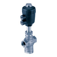
Table of Contents
Table of Contents
3
Contents
4
General Information
4
Symbols
4
Safety Instructions
4
Scope of Delivery
5
Guarantee Provisions
5
General Description
5
Technical Data
6
Design
6
Actuator Size
7
Material
7
Fluids
7
Temperature Range
8
Maximum Pilot Pressure 2/2-Way and 3/2-Way Valve
9
Operating Pressure 3/2-Way Valve
9
Minimum Pilot Pressures
10
Port Connections
12
Pressure Surge Test to DIN 1988, Part 2
12
Commissioning
13
Installation of Valve
13
Connections for 3/2-Way Valve
13
Electrical Connection of Pilot Valve
14
Maintenance and Servicing
15
Repair
15
Spare Parts
15
Spare Parts Drawings
17
Advertisement
Related Products
Burkert 20022861
Burkert 2000 INOX
Burkert 2006
Burkert 20039252
Burkert 20039262
Burkert 20032565
Burkert 20032576
Burkert 20032568
Burkert 20032571
Burkert 20032572
Burkert Categories
Control Unit
Controller
Measuring Instruments
Transmitter
Accessories
More Burkert Manuals
Login
Sign In
OR
Sign in with Facebook
Sign in with Google
Upload manual
Upload from disk
Upload from URL