Sign In
Upload
Manuals
Brands
Bruker Manuals
Laboratory Equipment
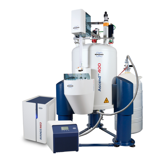
AVANCE NEO
Bruker AVANCE NEO Manuals
Manuals and User Guides for Bruker AVANCE NEO. We have
2
Bruker AVANCE NEO manuals available for free PDF download: User Manual
Bruker AVANCE NEO User Manual (120 pages)
Brand:
Bruker
| Category:
Laboratory Equipment
| Size: 6 MB
Table of Contents
Table of Contents
3
Introduction
7
Units Used Within this Manual
7
Table 1.1: Metric to American Conversion Factors
8
Safety
9
The Magnetic Field
9
Figure 2.1: Stronger Fringe Fields in Vertical Direction than in Horizontal Direction
9
Exclusion Zone
10
Security Zone
10
The Safety Lines
10
Table 2.1: Action Levels for Magnetic Flux Density of Static Magnetic Fields
10
The 0.5 Mt (5 Gauss) Line
11
The 3.0 Mt (30 Gauss) Line
11
Table 2.2: Elvs for External Magnetic Flux Density (B ) and 0 to 1 Hz
12
Standards on Health and Safety in the Workplace
12
Table 2.3: Example of Maximum Retention Periods
13
Transport and Rigging Safety
14
Table 2.4: BGV B15 Standards for Standard Precautions and Users
14
Table 2.5: BGV B15 Standards under Special Conditions for Selected Subgroups
14
Ventilation
15
Regular Ventilation
15
Emergency Ventilation
15
Oxygen Level Sensors
16
Safe Handling of Cryogenic Substances
16
What Is a Quench
16
Liquid Nitrogen Refills
17
Liquid Helium Refills
17
Country-Specific Safety Regulations
18
Safety from Nearby Construction
18
Earthquake Safety
18
Emergency Planning
19
Fire Department Notification
19
System Components
21
Superconducting Magnet Components
21
Console and Other System Components
22
Figure 3.1: Spectrometer and Magnet Control
22
Cryoprobe System (Optional)
23
Figure 3.2: Cryoprobe System
23
Cryoprobe Prodigy System (Optional)
24
Figure 3.3: Cryoprobe Prodigy with Pump & Control Unit and LM2 Tank
24
Other Optional Components
25
Figure 3.4: Other Options for AVANCE NEO Systems
25
Considerations for Off-Loading on Site
27
Magnet Access and Rigging
27
Considerations for Transport to the NMR Laboratory
28
Transport Dimensions and Weights
29
Magnet Transport Dimensions
29
Table 4.1: Door Dimensions: Standard Bore 54 MM
29
Table 4.2: Door Dimensions: Wide Bore 89 MM
30
Table 4.3: Door Dimensions: Super Wide Bore 154 MM
30
Magnet Stand Transport Dimensions
31
Table 4.4: Door Dimensions for Magnet Stand: Standard Bore 54 MM
31
Magnet Transport Weights
32
Table 4.5: Door Dimensions for Magnet Stand: Wide Bore 89 MM
32
Table 4.6: Door Dimensions for Magnet Stand: Super Wide Bore 154 MM
32
Table 4.7: Magnet Transport Weights: Standard Bore 54 MM
32
Table 4.10: Door Dimensions for Magnet Room Access: Spectrometers
33
Table 4.9: Magnet Transport Weights: Super Wide Bore 154 MM
33
Table 4.8: Magnet Transport Weights: Wide Bore 89 MM
33
Spectrometer and Accessories Transport Dimensions and Weights
33
Table 4.11: Crate Dimensions and Weights for Accessories
34
Rigging Equipment
35
Figure 4.1: A-Frame Gantry for Lifting the Magnet Inside the Magnet Room
35
Ceiling Height Requirements
37
Helium Transfer Line
38
Figure 5.1: Ceiling Height Requirements
38
Figure 5.2: Helium Transfer Lines
39
Table 5.1: Helium Transfer Line Dimensions
39
Minimum Ceiling Height
40
Table 5.2: Minimum Ceiling Height Requirements: Standard Bore 54 MM
41
Table 5.3: Minimum Ceiling Height Requirements: Wide Bore 89 MM
41
Table 5.4: Minimum Ceiling Height Requirements: Super Wide Bore 154 MM
41
Magnetic Fringe Fields
43
Table 6.1: Effects of Magnetic Fields on Equipment
43
Horizontal Fringe Fields
44
Table 6.2: Horizontal Fringe Fields: Standard Bore 54 MM
44
Table 6.3: Horizontal Fringe Fields: Wide Bore 89 MM
44
Table 6.4: Horizontal Fringe Fields: Super Wide Bore 154 MM
44
Vertical Fringe Fields
45
Table 6.5: Vertical Fringe Fields: Standard Bore 54 MM
45
Table 6.6: Vertical Fringe Fields: Wide Bore 89 MM
45
Table 6.7: Vertical Fringe Fields: Super Wide Bore 154 MM
45
Fringe Field Plots
46
Figure 6.1: Example of a Fringe Field Plot
46
Environment and Site Survey Measurement
47
Vibrations
47
Figure 7.1: Threshhold Values of Floor Acceleration
48
General Vibration Guidelines
48
Integrated Isolator Options
48
Table 7.1: Application and Interpretation of the Generic Vibration Criterion (VC) Curves
49
Measuring Floor Vibrations
50
Floor Vibration Guidelines: Bruker EMI Damping System
50
Figure 7.2: Threshold Values of Floor Acceleration: Tolerance Level for EMI Dampers
50
Table 7.2: EMI Damping System (Elastomeric Isolators)
50
Figure 7.3: Example of the Bruker Tolerance Level for Elastomer Dampers. Resolution <0.125
51
Figure 7.4: Elastomer Dampers
51
Floor Vibration Guidelines: Bruker Nano-C and Nano-D
52
Figure 7.5: Example of the Bruker Tolerance Level for ADI Dampers. Resolution <0.125 Hz
52
Table 7.3: ADI Damping System (Elastomeric Isolators)
52
Floor Vibration Guidelines: Bruker Nano-C API Damping System
53
Figure 7.6: ADI Dampers
53
Figure 7.7: Tolerance Level Nano-C for API Dampers
53
Table 7.4: Tolerance Level for API Damping System
54
Figure 7.8: Example of the Bruker Tolerance Level for API Dampers. Resolution <0.125 Hz
54
Figure 7.9: Schematic Drawing of an API Type Damping System
54
Magnetic Environment
55
Guidelines for Static Objects
55
Guidelines for Moving Objects
55
Table 7.5: Recommendations for Static Magnetic Objects
55
Table 7.6: Recommendations for Moveable Magnetic Objects
55
Electromagnetic Interference
56
Types of EMF Interference
56
DC EMF Interference
56
Measuring DC Fluctuating Fields
57
Guidelines for DC Interference
57
Reducing DC Interference
57
AC EMF Interference
58
Measuring AC EMF Interferences
58
Figure 7.10: Specification Framework with the Magnetic Field Represented as 0 to Peak Values
59
Guidelines for AC EMF Interference
59
HF Interference
59
Reducing AC EMF Interference
59
Measuring HF Fluctuating Fields
60
Most Commonly Studied Nuclei
60
Guidelines for HF Interference
60
Reducing HF Interference
60
Table 7.7: List of most Commonly Studied Nuclei and Corresponding Resonance Frequencies
60
Utility Requirements
61
Electrical Power Requirements
61
Table 8.1: Requirements of Basic System (2 Channels)
62
Figure 8.1: AVANCE Spectrometer with Internal Preamp
63
System Grounding and Potential Equalization of Avance Systems
63
Compressed Gas
64
General Requirements
64
Figure 8.2: AVANCE Spectrometer with External Preamp (HPPR/2)
64
Telecommunication
64
Gas Supply
65
Table 8.2: Pressure and Flow Requirements
65
Other Specifications
66
Table 8.3: VT Nitrogen Gas Quality (500 Mhz and Above)
66
Compressed Air System
67
Figure 8.3: Example of a Typical Dryer/Filter System Setup
67
Air Compressors
68
Dryers
69
Cooling Water
70
Filters
70
Liquid Nitrogen Requirements
70
Lighting
71
HVAC (Heating Ventilation Air Conditioning)
71
Heat Dissipation into the Room
72
Table 8.4: Maximum Humidity in the NMR Laboratory
72
Table 8.5: Heat Dissipation into the Room by Typical AVANCE NEO Systems
72
System Stability
73
Emergency Ventilation During Installation and Quenches
73
Table 8.6: Total Gas Volume and Maximum He Gas Flow: Standard Bore 54 MM
74
Table 8.7: Total Gas Volume and Maximum He Gas Flow: Wide Bore 89 MM
74
Table 8.8: Total Gas Volume and Maximum He Gas Flow: Super Wide Bore 154 MM
74
Emergency Exhaust Solutions
75
Figure 8.4: Emergency Quench Pipes
76
Fire Detection System and Fire Extinguishers
77
Floor Plan
79
Magnet Location
79
Figure 9.1: Top View of an Ascend Magnet
79
Dimensions and Mass of Equipment
80
Floor Load
80
Table 9.1: Dimensions and Weights of NMR Equipment
80
Figure 9.2: Magnet Dimensions
81
Table 9.2: Magnet Dimensions and Weight: Standard Bore 54 MM
82
Table 9.3: Magnet Dimensions and Weight: Wide Bore 89 MM
82
Table 9.4: Magnet Dimensions and Weight: Super Wide Bore 154 MM
82
Floor Types
83
Magnet Pits
83
Figure 9.3: Example of a Simple Magnet Platform
84
Magnet Platform
84
Helium Flex Lines
84
Maximum Field Strengths for NMR Equipment
85
Cabinet Position
85
Worktable Position
85
Table 9.5: Maximum Field Strength for NMR Equipment
85
Service Access Requirements
86
Layout Examples
87
Figure 9.4: Ascend 400 Layout Example
87
Figure 9.5: Top View of the Ascend 400 Magnet
88
Figure 9.6: 800 Mhz Layout Example
89
Figure 9.7: Top View of the Ascend 800 Magnet
90
Cryoprobe and Other Accessories
91
Figure 10.1: Cryoprobe System Overview
92
Table 10.1: Cryocooling Unit Specifications
93
Cryocooling Unit
93
Available Models
93
Helium Compressors
93
Helium Compressor - Indoor Water Cooled
94
Figure 10.2: Admissible Ranges for the Temperature and Flow of the Cooling Water
94
Figure 10.3: Cooling Water Typical Flow Characteristics
94
Table 10.2: Cooling Water Specifications
95
Helium Compressor - Indoor Air Cooled
96
Figure 10.4: Helium Compressor - Indoor Water Cooled
96
Figure 10.5: Helium Compressor - Indoor Air Cooled
96
Helium Compressor - Outdoor Air Cooled
97
Space Requirements and Specifications
97
Indoor Helium Compressors
97
Figure 10.6: Helium Compressor - Outdoor Air Cooled
97
Outdoor Helium Compressors
98
Table 10.3: Technical Data for Indoor Compressors
98
Helium Cylinders
99
Summary of Cryoprobe Options
99
Table 10.4: Technical Data for Outdoor Compressors
99
Cryoprobe Prodigy System (Optional)
101
Figure 10.7: Cryoprobe Prodigy and Control Unit
101
Table 10.5: Prodigy System Equipment Dimensions
102
Table 10.6: Prodigy System Electrical Requirements
102
Table 10.7: Prodigy System N
102
Cryofit
103
Introduction
103
Installation Requirements
103
Table 10.8: Prodigy System Ventilation Requirements
103
Table 11.1: Overview of Magnet Commissioning
105
Overview
105
Accessibility
105
11 Installation
105
Installation Requirements Checklist
106
Installation Procedure
106
Magnet Assembly
106
Table 11.2: Installation Requirements Checklist
106
Magnet Evacuation and Flushing with Nitrogen Gas
107
Cooling the Magnet to Liquid Nitrogen Temperature
107
Cooling the Magnet to Liquid Helium Temperatures
107
Charging the Magnet
107
Table 11.3: Magnet Transport Weights: Standard Bore 54 MM
108
Table 11.4: Magnet Transport Weights: Wide Bore 89 MM
109
Table 11.5: Magnet Transport Weights: Super Wide Bore 154 MM
109
12 Contact
111
List of Figures
113
Advertisement
Bruker AVANCE NEO User Manual (86 pages)
Beginners Guide
Brand:
Bruker
| Category:
Laboratory Equipment
| Size: 4 MB
Table of Contents
Table of Contents
3
1 Introduction
5
Sources of Hazards
5
Software Version and Command Syntax
5
2 Safety
7
Magnetic Safety
7
Cryogenic Safety
7
Electrical Safety
7
Chemical Safety
8
CE Certification
8
3 Introductory Theory and Terminology
9
Figure 3.1: Excitation and Response
9
Figure 3.2: NMR Spectrum
10
NMR Analysis of Chloroform
11
Figure 3.3: NMR Analysis of CHCI3
11
Figure 3.4: NMR Signals Emitted by CHCI3
12
Figure 3.5: Converting Hertz and Ppm
13
Proton NMR - Chemical Shift
14
Figure 3.6: 1H Chemical Shifts in Organic Compounds
14
Proton Spectrum of Benzene
15
Figure 3.7: Benzene Ring
15
Figure 3.8: Spectrum of Benzene
15
Proton Spectrum of Benzylacetate
16
Figure 3.9: Benzylacetate
16
Proton Spectrum of Ethylbenzene with Spin/Spin Coupling
17
Figure 3.10: Proton Spectrum of Benzylacetate
17
Figure 3.11: Ethylbenzene
18
Figure 3.12: Ethylbenzene Spectrum
18
Decoupling
19
Figure 3.13: Decoupling Experiment
20
Figure 3.14: Ethylbenzene Spectrum with Homodecoupling
20
FID and Spectrum
21
Figure 3.15: Fourier Transformation
21
4 System Description
23
Figure 4.1: AVANCE NEO Console and Ascend Magnet
23
AVANCE Architecture Overview
24
Operator Console and Connections
24
Figure 4.2: AVANCE NEO Architecture Overview
24
Console
25
Link between the Host Computer and the AQS
26
Magnet, Shim System, HPPR and Probe
26
Figure 4.3: Photo of Magnet, Shim System, Probe and HPPR
26
The Magnet and Magnet Dewar
27
Room Temperature Bore
28
Figure 4.4: Superconducting Magnet
28
Helium Tank
29
Nitrogen Tank
29
Introduction to the Lock System
29
Probes
30
Figure 4.5: Sample in Probe
30
Figure 4.6: Typical HPPR Cabling
31
Broadband Probe
32
Figure 4.7: Example of a Broadband Probe
32
Iprobe
33
Figure 4.8: the Bruker Iprobe Platform
33
Changing a Probe
34
5 Basic Procedures
35
The Topspin Window
35
Creating a New Data Set
36
Sample Preparation
38
Figure 5.1: Inserting the Sample into the Spinner
38
Inserting the Sample Plus Spinner into the Magnet
39
Locking the Sample
39
Figure 5.2: Solvents Table
39
Tuning and Matching the Probe
40
Probes Equipped with ATM Using the Automated Tuning Routine
40
Figure 5.3: Lock Display after Locking the Sample
40
Probes Equipped with ATM Using the Manual Tuning Routine
41
Figure 5.4: ATMM Probe Tuning/Matching Window
41
Spinning the Sample
43
Figure 5.5: Examples of Wobble Curves with Different Tuning and Matching
43
Shimming
44
Routine Shimming Using Topshim
44
Setting the Probe/Solvent Dependent Parameters
44
Adjusting the Receiver Gain
44
Starting the Acquisition
44
Processing the Data
45
Figure 5.6: the Proc1D Window
45
6 Preparing for Acquisition, Frequency Related Parameters
47
Frequency
47
Numerical Explanation of Transmitted, Basic and Offset Frequencies
48
Figure 6.1: Spectrum with BF1 = 600.13 Mhz, 01 = 0 Hz
48
Figure 6.2: Spectrum with BF1 =600.13 Mhz, 01= 8 Khz
49
Figure 6.3: Spectrum with BF1 = 600.13 Mhz, 01 = 8 Khz, SWH = 8.4 Khz
49
Figure 6.4: Interaction of SFO1, BF1 and O1
50
7 The NMR Sample
51
Solvent Selection
51
Sample Tube
52
Figure 7.1: Spectrum Showing Spinning Sidebands
52
Sample Handling
53
8 Proton Spectrum
55
Experiment Setup
55
Acquisition
59
Processing
59
Integration
61
Plotting the 1D Proton Spectra
63
Optimizing the Sweep Width
64
9 ¹³C Spectrum with Proton Decoupling
67
Experiment Setup
68
Acquisition
70
Processing
70
Peak Picking
72
Plotting the 1D Carbon Spectrum
73
10 Contact
75
List of Figures
77
List of Tables
79
Glossary
81
Index
83
Advertisement
Related Products
Bruker AVANCE
Bruker Anton Paar
Bruker AQS
Bruker AQX
Bruker 300'154 Ascend DNP
Bruker 300'89 Ascend
Bruker 500'54 Ascend ULH
Bruker 500'89 Ascend Aeon
Bruker 600'54 Ascend ULH
Bruker 700'54 Ascend
Bruker Categories
Laboratory Equipment
Measuring Instruments
Industrial Equipment
Security Sensors
Amplifier
More Bruker Manuals
Login
Sign In
OR
Sign in with Facebook
Sign in with Google
Upload manual
Upload from disk
Upload from URL