Sign In
Upload
Manuals
Brands
Bruker Manuals
Laboratory Equipment
Anton Paar
Bruker Anton Paar Manuals
Manuals and User Guides for Bruker Anton Paar. We have
1
Bruker Anton Paar manual available for free PDF download: User Manual
Bruker Anton Paar User Manual (136 pages)
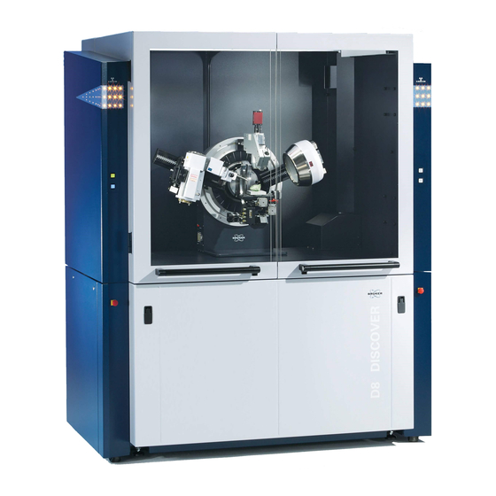
Temperature Chambers for D8 ADVANCE / D8 DISCOVER
Brand:
Bruker
| Category:
Laboratory Equipment
| Size: 42 MB
Table of Contents
Table of Contents
3
List of Figures
7
1 Safety Guidelines
13
About this Manual
13
Qualified Personnel
14
Correct and Intended Usage
15
Disclaimer and Liability
15
General Safety Precautions
15
Signage
18
2 General Remarks
19
Heating Principles
19
Temperature Measurement and Calibration
20
Temperature Measurement
20
Temperature Calibration
21
Temperature Calibration by Thermal Expansion of Mgo (Periclase)
21
Detailed Procedure for Temperature Determination
22
Shortened Procedure for Temperature Determination
23
Figure 2.1: Temperature Dependence of Lattice Parameter A0 of Mgo
23
Temperature Calibration by Phase Transitions
24
3 Vacuum Equipment
27
Installation of the Edwards High Vacuum Stage with TIC
27
Mounting of the Edwards High Vacuum Stage
27
Figure 3.1: Mounting the Edwards Turbomolecular Pump to the Flexible Bellow
28
Figure 3.2: Connecting the Vacuum Tube to the HTK 1200N Chamber
28
Figure 3.3: Mounting the Edwards Backing-Pump to the Flexible Vacuum Line
29
Figure 3.4: Back Sides Of: Edwards Turbomolecular Instrument Controller (TIC, Left Side) and Edwards Relay Box (Right Side)
30
Operation of the Edwards High Vacuum Stage
31
Figure 3.5: Starting Screen for the TIC Controller
31
Installation of the Edwards Backing-Pump
32
Figure 3.6: Vacuum Sensor, Flooding Valve, Tube to Chamber and Mist-Filter Mounted
32
Figure 3.7: Display and Backside of the Vacuum Indicating Instrument
33
4 Adjustment of a Chamber on the D8
35
Adjustment Procedures
35
Adjustment Procedure with Alignment Slit
36
Figure 4.1: Rocking Curve to Check Chamber Rotation Error
38
Figure 4.2: Final Position after Rotation Correction
39
Alternative Procedure Without Alignment Slit
40
Figure 4.3: Insert a Deflection Angle in CONFIGURATION for the Temperature Stage
40
Figure 4.4: Z-Scan over a Wide Range to Roughly Determine the Right Sample Height
41
Figure 4.5: more Accurate Z-Scan to Determine the Right Sample Height
42
Figure 4.6: Rocking Curve at Correct Sample Height
43
Using Automated Height Correction
44
Figure 4.7: Inserting the Temperature Depending Z-Positions
46
5 Mounting the Temperature Controller into the D8 Enclosure
47
Figure 5.1: Removing the Covers for Rack Mounting
47
Figure 5.2: Fixing the Guide Bars on both Sides of the Paar Controller
47
Figure 5.3: Removing the Supporting Feet for Rack Mount
48
6 Installation and Operation of the HTK-Series, TTK 600, XRK 900, and HPC 900 Chambers
49
Introduction
49
Mounting the Chamber to the Goniometer
50
Figure 6.1: HTK 1200N Mounted on a Goniometer
50
Figure 6.2: Red Dots for the Bayonet Fixture in the "Locked" Position
51
Figure 6.3: Fixing Screws for the TTK 600 Adapter
51
Figure 6.4: HTK 1200N Mounted on a Goniometer
52
Temperature Controllers for Anton Paar Chambers
53
Figure 6.5: TCU Series Controller with Built-In Eurotherm 2604 Controller
53
Figure 6.6: CCU Series Controller
53
Connecting the TCU Controller
54
Figure 6.7: Front View of TCU110C Mounted in a D8 DISCOVER
54
Figure 6.8: Connecting Serial Lines to the Universal IO-Board
55
Configuring the Chamber in DIFFRAC.MEASUREMENT CENTER
56
Operation
56
Alignment
57
7 Installation and Operation of the CHC Plus Humidity Chamber
59
Introduction
59
Mounting the Chamber to the Goniometer
59
Temperature Controllers and Water Circuit for CHC Plus
60
Figure 7.1: CHC Plus Chamber Fully Mounted on Vertical Diffractometer
60
Figure 7.2: Front View of TCU110
61
Figure 7.3: Front View of a CCU100 Controller
61
Figure 7.4: Front View of MHG Controller
61
Figure 7.5: Julabo Waterbath (Corio CD-201F)
62
Figure 7.6: Power Supply Multiple Socket
63
Figure 7.7: MHG Power Supply Adapter
63
Figure 7.8: Back Side of Julabo Waterbath (Corio CD-201F)
64
Connecting the CCU Controller
65
Connecting the MHG for CHC Plus
65
Figure 7.9: Back View of CCU100
65
Figure 7.10: Back View of MHG Controller
65
Figure 7.11: RS232 Connection from UIOB to Temperature Controller, MHG Controller and Ju
66
Figure 7.12: CPU Board with USB Connection of the Corio Water Bath
67
Figure 7.13: RS232 Connections from UIOB to Julabo Heating Circulator and Water Connections
68
Configuring the Chamber in DIFFRAC.MEASUREMENT CENTER
69
Operation
69
Figure 7.14: Water Flow Controller
69
Figure 7.15: Setting a New Temperature and Humidity with COMMANDER
71
Figure 7.16: Selecting the Temperature Mode in the COMMANDER
71
Alignment
72
8 Installation and Operation of the DCS 350 and DHS 1100 Chambers
73
Introduction
73
Mounting the Chamber to the Goniometer
73
Figure 8.1: Fixing the DCS 350 Onto the Sample Stage
74
Temperature Controllers DC S350 and DHS 1100
75
Figure 8.2: Fixing the DHS 1100 Onto the Sample Stage
75
Configuring the Chamber in DIFFRAC.MEASUREMENT CENTER
76
Figure 8.3: Front View of a TCU Series Controller with Built-In Eurotherm 2604 Controller
76
Figure 8.4: Front View of a CCU100 Controller
76
Operation
77
Activating the Chamber in da VINCI
77
Figure 8.5: da VINCI Overview with Sample Stage
78
Operating the Chamber
79
Figure 8.6: da VINCI with DHS 1100 Selected
79
Figure 8.7: Temperature Control Field in COMMANDER
79
Figure 8.8: Setting a New Temperature and Heating Rate with COMMANDER
80
Figure 8.9: Selecting the Temperature Mode in the COMMANDER
80
Alignment
81
Aligning the Chamber for Automated Height Correction
81
Figure 8.10: Z-Scan at 25 °C over a Wide Range to Determine Roughly the Height Position
82
Figure 8.11: Z-Scan at 25 °C with Determination of Height Position
83
Figure 8.12: Rocking-Curve Scan at 25 °C with Determination of Rotation Error
84
Figure 8.13: Inserting the Temperature Depending Z-Positions and Activating Them
86
Optimizing Theta, Two Theta and Psi
87
Optimizing Theta
87
Figure 8.14: Rocking Curve to Align the Angle Theta (or Omega in HR Mode) between Source and Sample
87
Optimizing Two Theta
88
Figure 8.15: Twotheta Scan to Align the Bragg Angle
88
Optimizing Psi
89
Figure 8.16: Psi Scan to Align the Diffracting Plane Normal in the Diffraction Plane
89
Creating a Temperature Dependent Measurement Using the WIZARD
90
Figure 8.17: Transmit Drive Positions from COMMANDER to WIZARD
90
Figure 8.18: Create an HR-XRD Measurement for Your Sample
90
Figure 8.19: Selecting the Aligned Sample Reflection
91
Figure 8.20: Import the Centered Values from COMMANDER
91
Figure 8.21: Defining a Sequence of Measurements
92
Figure 8.22: Setting the Drives for Alignment for the each Temperature
93
Figure 8.23: Create a Job Using the Measurealign.cs Script
94
9 Installation and Operation of the BTS 150 and BTS 500 Chambers
95
Introduction
95
Mounting the Chamber to the Goniometer
95
Figure 9.1: Fixing Screws for the BTS 150/500 Adapter
96
USB Connection of the BTS 150/500 to the CPU1 Board
97
Figure 9.2: USB Connection of the BTS 150/500 to the CPU1 Board in the USB1 Slot
97
Configuring the Chamber in DIFFRAC.MEASUREMENT CENTER
98
Operation and Alignment
98
10 Appendix / Service Details
99
Vacuum Equipment
99
Programming of the Edwards High Vacuum Stage
99
Configuring a Chamber in DIFFRAC.MEASUREMENT CENTER
100
HTK-Series, TTK 600, XRK 900, and HPC 900 Chambers
100
Figure 10.1: Import Template from File
101
Figure 10.2: Select Template
102
Figure 10.3: Import Sections
102
Figure 10.4: Section for HTK1200N in Goniometer/Center/Paar_Z_Htk1200
103
Figure 10.5: Section HTK1200N in Goniometer/Center/Paar_Z_Htk1200/Htk1200
104
Figure 10.6: Section for Nonambient Controller
104
Figure 10.7: Subsection Tcu1000_Controller for Nonambient Controller
105
Figure 10.8: Setting a New Temperature and Heating Rate with COMMANDER
106
Figure 10.9: Selecting Serialline/Power X1_RS232_I/-II for Serialconnector
106
CHC Plus
107
CHC Plus with TCU 110 and HE-4 Water Bath
107
Figure 10.10: Selecting Serialline/Full X2_RS232_I/-II for Serialconnector
107
Figure 10.11: Import Section Stage_Paar_Chcplus_Ln2Cooling.bfscn
108
Figure 10.12: Import Sections
108
Figure 10.13: Sections Created for CHC Plus
109
Figure 10.14: Chc_Stage Chamber Temperature Details
110
Figure 10.15: Chc_Stage Sample Temperature Details
111
Figure 10.16: TOOLS Information for Actual Parameters of CHC Plus
112
Figure 10.17: CHC Plus Controller Details
113
Figure 10.18: CHC Plus Chamber Temperature and Adjacent Water Temperatures
113
Figure 10.19: CHC Plus MHG Controller Details
114
Figure 10.20: CHC Plus TCU110 Controller Details
114
Figure 10.21: CHC Plus Watercircuit Controller Details
115
Figure 10.22: Control Rack Uioboard Serial Connections for MHG, TCU110 and Water Circuit (Julabo HE-4)
116
CHC Plus with CCU100 and Corio Water Bath
117
Figure 10.23: Import the Chcplus Template in Measurement Center
118
Figure 10.24: Import Section for CHC Plus
118
Figure 10.25: Sections Created for CHC Plus
119
Figure 10.26: Chc_Stage Chamber Temperature Details
119
Figure 10.27: Chc_Stage Humidity Details
120
Figure 10.28: Chc_Stage Sample Temperature Details
121
Figure 10.29: CHC Plus CPU Activation for USB Connection
121
Figure 10.30: CHC Plus Controller Details
122
Figure 10.31: CHC Plus Chamber Temperature and Adjacent Water Temperatures
122
Figure 10.32: CHC Plus MHG Controller Details
123
Figure 10.33: CHC Plus CCU100 Controller Details
123
Figure 10.34: CHC Plus Corio Watercircuit Controller Details
124
Figure 10.35: Control Rack Uioboard Serial Connections for MHG and CCU100 Controller
124
Figure 10.36: Control Rack Cpuboard USB Connections for Corio Water Circuit (Julabo)
125
Figure 10.37: TOOLS Information for Actual Parameters of CHC Plus
125
DCS 350 and DHS 1100
126
Figure 10.38: Setting the Plug for Sampleattachments
126
Figure 10.39: Selecting Serialline/Power X1_RS232_1/-2 for Serialconnector
127
Figure 10.40: Selecting Serialline/Full X2_RS232_1/-2 for Serialconnector
127
Figure 10.41: Introducing the Board CPU to the Controllers Section
127
Figure 10.42: Selecting Serialline/Full TTYS0/1 for Serialconnector
128
Figure 10.43: Connecting Serial Lines to the Universal IO-Board
129
Figure 10.44: Connecting Serial Lines to the CPU Board
130
BTS 150 and BTS 500
131
Figure 10.45: Import Template Button
131
References
132
Figure 10.46: BTS 500 Connector Configuration
132
Index
133
Advertisement
Advertisement
Related Products
Bruker AVANCE NEO
Bruker AVANCE
Bruker AQS
Bruker AQX
Bruker 300'154 Ascend DNP
Bruker 300'89 Ascend
Bruker 500'54 Ascend ULH
Bruker 500'89 Ascend Aeon
Bruker 600'54 Ascend ULH
Bruker 700'54 Ascend
Bruker Categories
Laboratory Equipment
Measuring Instruments
Industrial Equipment
Security Sensors
Accessories
More Bruker Manuals
Login
Sign In
OR
Sign in with Facebook
Sign in with Google
Upload manual
Upload from disk
Upload from URL