Sign In
Upload
Manuals
Brands
Brooks Manuals
Controller
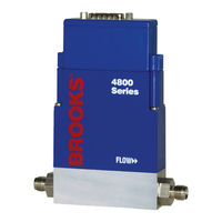
4800 Series
Brooks 4800 Series Manuals
Manuals and User Guides for Brooks 4800 Series. We have
2
Brooks 4800 Series manuals available for free PDF download: Supplemental Manual, Installation And Operation Manual
Brooks 4800 Series Supplemental Manual (108 pages)
S-Protocol over RS485 MFCs/MFMs
Brand:
Brooks
| Category:
Controller
| Size: 1 MB
Table of Contents
Table of Contents
5
1 Introduction
11
How to Use this Manual
11
Description
11
Specifications
12
Definition of Terms
12
2 Receipt & Storage
13
Receipt of Equipment
13
Recommended Storage Practice
14
Return of Equipment
14
Transit Precautions
15
Removal from Storage
15
3 Background & Numbering
17
Background
17
Numeric System
17
4 Installation
19
Start up / Assumption
19
Supported Baud Rates
19
Bus and Device Leds
19
Table 2.2-1 Bus Led Specification
19
Figure 2.2-1 RS485 Label on Cover
19
Device Wiring
20
Electrical Connections
20
Table 2.2-2 Device Led Specification
20
Table 2.2-3 Pin-Outs for D-Sub Connectors
20
Alarm Output
21
Multi Drop
21
Figure 2.2-2 Open Collector Alarm Output Connection Example
21
Table 2.2-4 D-Connector Communication Pins
22
Figure 2.2-3 RS-485 Multi Drop Interconnection DMFM/C and PC
22
5 Message Protocol Structure
23
Introduction
23
Addressing Concept
23
Character Coding
23
Message Format
24
Message Structure
24
Figure 5-1Single Character Bit Sequence
24
Figure 5-2 HART Message Structure
24
Preamble Characters
25
Start Character
25
Figure 5-3 Start Character Settings
25
Address Characters
26
Table 5-1 Start Character Codings (Hexadecimal)
26
Figure 5-4 Short Frame Address Character
26
Figure 5-5 Long Frame Address Characters
27
Command Character
28
Byte Count Character
28
Status Characters
29
Table 5-2 Status Bytes Coding
29
Data Characters
30
8-Bit Unsigned Integer Format
30
24-Bit Unsigned Integer Format
30
IEEE 754 Floating Point Format
30
Table 5-3 IEEE 754 Single Precision Floating Point Standard
30
ASCII Data Format
31
Packed-ASCII (6-Bit ASCII) Data Format
31
Figure 5-6 Packed-ASCII Construction
31
Checksum Character
32
Table 5-4 Packed-ASCII Codes
32
6 Master Slave Communication
33
Introduction
33
Line Handling
33
Establishing Communications with a Device
35
Example of Using Command #11
36
Table 6-1 Converting Tag Name to Packed ASCII
36
Figure 6-2 Command 11 Response to Long Frame Address
36
Alarm Configuration and Monitoring
39
Error Handling
40
Examples
41
Reading Flow Rate
41
Setting the Setpoint
42
7 General Transmitter Information
45
Referenced Documents
45
Unit Conversions
45
Flow Rate Conversions
45
Temperature Conversions
46
8 Universal Command Specifications
47
Command #0: Read Unique Identifier
47
Command #1: Read Primary Variable
49
Command #2: Read Primary Variable Current and Percent of Range
50
Command #3: Read Current and All Dynamic Variables
51
Command #6: Write Polling Address
52
Command #11: Read Unique Identifier Associated with Tag
54
Command #12: Read Message
56
Command #13: Read Tag, Descriptor, Date
57
Command #14: Read Primary Variable Sensor Information
58
Command #15: Read Output Information
59
Command #16: Read Final Assembly Number
61
Command #17: Write Message
62
Command #18: Write Tag, Descriptor, Date
64
Command #19: Write Final Assembly Number
66
9 Common Practice Command Specifications
67
Command #37: Set Primary Variable Lower Range Value
67
Command #38: Reset Configuration Changed Flag
68
Command #48: Read Additional Transmitter Status
69
Command #59: Write Number of Response Preambles
71
Command #122: Write Device Identification Number (NON-PUBLIC)
72
10 Transmitter Specific Command Specifications
75
Command #128: Enter/Exit Write Protect Mode (NON-PUBLIC)
75
Command #129: Clear Address Related Device Data (NON-PUBLIC)
76
Command #130: Write Manufacturer's Device Type Code (NON-PUBLIC)
77
Command #150: Read Process Gas Type
78
Command #151 Read Gas Density, Flow Reference and Flow Range
79
Command #190: Read Standard Temperature and Pressure
81
Command #191: Write Standard Temperature and Pressure
82
Command #193: Read Operational Settings
84
Command #195: Select Gas Number
85
Command #196: Select Flow Unit
86
Command #197: Select Temperature Unit
87
Command #215: Read Setpoint Settings
88
Command #216: Select Setpoint Source
89
Command #230: Get Valve Override Status
90
Command #231: Set Valve Override Status
91
Command #235: Read Setpoint in % and Selected Units
92
Command #236: Write Setpoint in % or Selected Units
93
Command #237: Read Valve Control Value
95
Command #245: Read Alarm Enable Setting
96
Command #246: Write Alarm Enable Setting
97
Command #247: Read High/Low Flow Alarm
98
Command #248: Write High/Low Flow Alarm
99
11 Transmitter Specific Tables
101
Introduction
101
Device Type Codes
101
Flow Rate Unit and Reference Codes
101
Table 11-1 Flow Rate Unit Definition
101
Density Unit Codes
102
Table 11-2 Flow Reference Condition
102
Table 11-3 Density Unit Definition
102
Temperature Unit Codes
103
Pressure Unit and Reference Codes
103
Table 11-4 Temperature Unit Definition
103
Table 11-5 Pressure Unit Definition
103
Write Protect Codes
104
Physical Signaling Codes
104
Transmitter Variable Codes
104
Table 11-6 Pressure Reference Definition
104
Table 11-7 Write Protect Codes
104
Table 11-8 Physical Signaling Codes
104
Table 11-9 Transmitter Variable Code Definition
104
Flag Assignments
105
Analog Output Selection Codes
105
Setpoint Source Selection Codes
105
Table 11-10 Flag Assignments
105
Table 11-11 Analog Output Selection Codes
105
Table 11-12 Setpoint Source Selection Codes
105
Valve Override Codes
106
Table 11-13 Valve Override Codes
106
Additional Device Status and Masking
107
Table 11-14 Additional Device Status and Masking
107
Advertisement
Brooks 4800 Series Installation And Operation Manual (44 pages)
Local Operator Interface (LOI)
Brand:
Brooks
| Category:
Recording Equipment
| Size: 0 MB
Table of Contents
Table of Contents
5
Section 1 Introduction
7
Description
7
How to Use this Manual
7
Specifications
7
Pin-Outs for D-Connector to Remote Connection
9
Figures
10
LOI Dimensions
10
Section 2 Installation
13
General
13
Receipt of Equipment
13
Recommended Storage Practice
13
Return Shipment
14
Transit Precautions
14
Removal from Storage
14
Mechanical Connections
15
LOI Installed Using D-Type Connector
15
LOI Installed Using DC Power Plug
16
Section 3 Operation
17
Operating Procedures
17
General Display and Jog Dial Operation
17
LOI Display and Jog Dial
17
Scrolling to and Selecting a Menu Item
19
Changing and Saving a Value Setting
19
Main Menu
19
Configuration Functions
19
Gas Curve File
20
Flow Engineering Units
21
Setpoint Source
23
Ensuring Proper Setpoint Operation in Local and Remote Modes
24
Units Resolution
24
Dial Resolution
25
Backlight
26
Software and Hardware Versions
26
Zeroing
27
Output Selection
28
Reset to Factory Default
29
Changing the Setpoint
29
Valve Override
30
Totalizer
31
Viewing the Totalizer Value
32
Section 4 Maintenance
33
Overview
33
Setting the Flow Alarm
33
Displaying the Alarm Menu
33
Changing a Flow Alarm Value
34
Enabling the Flow Alarm
34
Alarm Output Pin
35
Alarm LED Indicator
35
Advertisement
Related Products
Brooks 4860
Brooks 4850
Brooks Polycold MaxCool 4000H
Brooks FluidX Aperio 4
Brooks PreciseFlex 400
Brooks 5850i
Brooks 5851EM Series
Brooks 5851i
Brooks 5866
Brooks 5965
Brooks Categories
Measuring Instruments
Controller
Laboratory Equipment
Security System
Robotics
More Brooks Manuals
Login
Sign In
OR
Sign in with Facebook
Sign in with Google
Upload manual
Upload from disk
Upload from URL