Sign In
Upload
Manuals
Brands
Biral Manuals
Water Pump
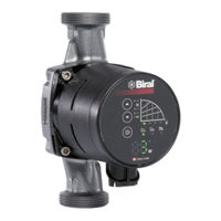
PrimAX 25-8 180 RED
Biral PrimAX 25-8 180 RED Pump Manuals
Manuals and User Guides for Biral PrimAX 25-8 180 RED Pump. We have
4
Biral PrimAX 25-8 180 RED Pump manuals available for free PDF download: Installation And Operating Instructions Manual, Quick Manual
Biral PrimAX 25-8 180 RED Installation And Operating Instructions Manual (156 pages)
Brand:
Biral
| Category:
Water Pump
| Size: 20 MB
Table of Contents
Deutsch
5
Table of Contents
5
1 Sicherheitshinweise
7
Allgemeines
7
Kennzeichnung von Hinweisen
7
Personalqualifikation und -Schulung
7
Gefahren bei Nichtbeachtung der Sicherheitshinweise
7
Sicherheitsbewusstes Arbeiten
7
Sicherheitshinweise für den Betreiber / Bediener
8
Sicherheitshinweise für Montage-, Wartungs- und Inspektionsarbeiten
8
Eigenmächtiger Umbau und Ersatzteilherstellung
8
Unzulässige Betriebsweisen
8
2 Verwendete Symbole
9
3 Allgemeine Informationen
10
Verwendungszweck
10
Anforderungen an das Fördermedium
10
Betriebsbedingungen
11
Rückschlagventil
12
Schutz vor Frosteinwirkung
12
Wärmedämmung
12
Durchflussrichtung
12
4 Montage
13
Allgemeine Hinweise
13
Durchspülen der Heizungsanlage (bei Ausgebauter Pumpe)
13
Einbau
13
Zulässige Einbaupositionen
13
Ändern der Einbauposition des Frequenzumrichters
14
Pumpenkopf Drehen
15
Pumpe in Anlage Montieren
16
5 Elektrischer Anschluss
17
Versorgungsspannung
17
Anschliessen der Spannungsversorgung
18
Biral Connector Anschliessen
19
Anschlussschema Klemmen-Beschriftung
19
Switch Einstellungen
20
Switch 1, Störmeldung oder Betriebsmeldung (Umschaltbar)
20
Switch 2, Extern aus oder Extern ein (Umschaltbar)
21
Switch 3, Power Limit (Aktivierbar)
21
Doppelpumpenausführung (91, 92)
21
6 Inbetriebnahme
22
Allgemeines
22
Betriebskontrolle
22
7 Einstellungen
23
Bedienfeld
23
Regelungsarten
23
Förderhöhe (A2)
24
Anzeige der Aktuellen Fördermenge
24
Übersicht Maximale Förderhöhe, Fördermenge
24
Bedienfeld Aktivieren / Deaktivieren
25
Pumpe START / STOP
25
Trockenlauferkennung Aktivieren / Deaktivieren
25
Biral-Impeller
26
Werkseitige Einstellung der Pumpe
26
8 Störungsübersicht und Checkliste
27
9 Sensor
29
10 Zubehör / Variante
30
Biral Remote
30
Biral Interface Module, BIM A2 Signalmodul (für Selbstregulierende Pumpen)
31
Biral Interface Module, BIM B2 Steuermodul (für Gesteuerte Pumpen)
31
11 Technische Daten
32
12 Entsorgung
32
13 Ersatzteilliste
33
Français
35
1 Consignes de Sécurité
37
Généralités
37
Symboles de Sécurité Utilisés Dans la Présente Notice
37
Qualification Et Formation du Personnel
37
Risques Et Dangers en Cas de Non Observation des Consignes de Sécurité
37
Observation des Règles de Sécurité
37
Consignes de Sécurité À L'intention de L'utilisateur / de L'opérateur
38
Consignes de Sécurité Relatives Au Montage, À L'entretien Et À la Révision
38
Modifications Et Pièces de Rechange
38
Conformité D'utilisation
38
2 Symboles Utilisés
39
3 Informations Générales
40
Finalité
40
Critères Liés Au Fluide D'alimentation
40
Conditions D'utilisation
41
Clapet de Retenue
42
Protection Contre Le Gel
42
Isolation Thermique
42
Sens D'écoulement
42
4 Montage
43
Remarques Générales
43
Rinçage de L'installation de Chauffage (en Cas de Pompe Démontée)
43
Positions Autorisées Pour Le Montage
43
Changement du Positionnement de Montage du Convertisseur de Fréquence
44
Tourner la Tête de la Pompe
45
Montage de la Pompe Dans L'installation
46
5 Raccordement Électrique
47
Alimentation
47
Raccordement de la Tension D'alimentation
48
Raccordement du Biral Connector
49
Schéma de Raccordement Marquage des Bornes
49
Réglages Switch
50
Switch 1, Störmeldung oder Betriebsmeldung (Umschaltbar)
50
Switch 2, Extern aus oder Extern ein (Umschaltbar)
51
Switch 3, Power Limit (Aktivierbar)
51
Version Jumelle (91, 92)
51
6 Mise en Service
52
Généralités
52
Contrôle de Fonctionnement
52
7 Réglages
53
Panneau de Commande
53
Modes de Régulation
53
Hauteur de Refoulement (A2)
54
Affichage du Débit Actuel
54
Aperçu de la Hauteur Maximale de Refoulement Et du Débit
54
Activation/Désactivation des Touches de Commande
55
START / STOP de la Pompe
55
Trockenlauferkennung Aktivieren / Deaktivieren
55
Turbine Biral
56
Réglage D'usine de la Pompe
56
8 Vue D'ensemble des Dérangements Et Liste de Contrôle
57
9 Capteur
59
10 Accessoires / Variante
60
Biral Remote
60
Biral Interface Module, BIM A2 Module de Signalisation
61
(Pour Pompes À Autorégulation)
61
Biral Interface Module, BIM B2 Module de Commande
61
(Pour Pompes Commandées)
61
11 Caractéristiques Techniques
62
12 Élimination
62
13 Liste des Pièces de Rechange
63
Italiano
65
1 Avvertenze DI Sicurezza
67
Generalità
67
Contrassegno Delle Avvertenze
67
Qualifica E Addestramento del Personale
67
Pericoli in Caso DI Inosservanza Delle Avvertenze DI Sicurezza
67
Lavoro in Conformità alle Avvertenze E Norme DI Sicurezza
68
Avvertenze DI Sicurezza Per L'esercente E L'operatore
68
Avvertenze DI Sicurezza Per I Lavori DI Montaggio, Manutenzione E Ispezione
68
Modifiche E Fabbricazione DI Parti DI Ricambio Senza Autorizzazione
68
Modalità D'uso Non Consentite
68
2 Simboli Utilizzati
69
3 Informazioni Generali
70
Campo DI Applicazione
70
Requisiti del Liquidi Pompato
70
Condizioni DI Funzionamento
71
Valvola DI Non Ritorno
72
Senso DI Flusso
72
4 Montaggio
73
Indicazioni Generali
73
Lavaggio Dell'impianto DI Riscaldamento (con Pompa Smontata)
73
Posizioni DI Montaggio Consentite
73
Cambiare la Posizione DI Montaggio del Convertitore DI Frequenza
74
Ruotare la Testa Della Pompa
75
Montare la Pompa Nell'impianto
76
5 Collegamento Elettrico
77
Tensione DI Alimentazione
77
Collegare L'alimentazione DI Tensione
78
Collegare Il Connettore Biral
79
Schema DI Collegamento Dicitura Morsetti
79
Impostazioni Switch
80
Switch 1, Indicazione DI Guasto O Indicazione DI Pronto (Commutabile)
80
Switch 2, off Esterno O on Esterno (Commutabile)
81
Switch 3, Power Limit (Attivabile)
81
Versione Gemellare (91, 92)
81
6 Messa in Funzione
82
Generalità
82
Controllo del Funzionamento
82
7 Impostazioni
83
Quadro DI Comando
83
Modalità DI Regolazione
83
Altezza Manometrica (A2)
84
Indicazione Della Portata Attuale
84
Prospetto Altezza Manometrica Massima, Portata
84
Attivare/Disattivare I Tasti DI Comando
85
START/STOP Della Pompa
85
Attivare / Disattivare Il Riconoscimento Funzionamento a Secco
85
Impeller Biral
86
Impostazioni DI Fabbrica Della Pompa
86
8 Vista D'insieme Dei Guasti E Check-List
87
9 Sensore
89
10 Accessori/Varianti
90
Biral Remote
90
Biral Interface Module, BIM A2 Signal Module (Per Pompe Autoregolanti)
91
Biral Interface Module, BIM B2 Control Module (Per Pompe Comandate)
91
English
95
1 Safety Information
97
General Remarks
97
Identification of Notices
97
Staff Qualification and Training
97
Risks in the Event of Non-Compliance with the Safety Information
97
Safety-Conscious Work
97
Safety Information for the Operator / Operating Personnel
98
Safety Information for Installation, Maintenance and Inspection Works
98
Unauthorised Reconstruction and Production of Spares
98
Improper Operating Methods
98
2 Symbols Used
99
3 General Information
100
Purpose
100
Requirements of the Delivery Medium
100
Operating Conditions
101
Non-Return Valve
102
Flow Direction
102
4 Installation
103
General Notes
103
Flushing Heating Equipment (for Extended Pump)
103
Permissible Installation Positions
103
Changing the Installation Position of the Frequency Converter
104
Rotate the Pump Head
105
Install the Pump in the Unit
106
5 Electrical Connection
107
Supply Voltage
107
Anschliessen der Spannungsversorgung
108
Connecting Biral Connector
109
Connection Drawing Clamp Description
109
Switch Settings
110
Switch 1, Störmeldung oder Betriebsmeldung (Umschaltbar)
110
Switch 2, Extern aus oder Extern ein (Umschaltbar)
111
Switch 3, Power Limit (Aktivierbar)
111
Twin Design (91, 92)
111
6 Start-Up
112
General
112
Operational Control
112
7 Settings
113
Control Panel
113
Regelungsarten
113
Delivery Height (A2)
114
Display of the Current Delivery Height
114
Summary of Maximum Delivery Height and Delivery Amount
114
Activating / Deactivating the Control Keys
115
START / STOP Pump
115
Activate / Deactivate Dry Running Detection
115
Biral Impeller
116
On-Site Adjustment of the Pump
116
8 Fault Summary and Checklist
117
9 Sensor
119
10 Accessories / Versions
120
Biral Remote
120
Biral Interface Module, BIM A2 Signal Module (for Self-Regulating Pumps)
121
Biral Interface Module, BIM B2 Control Module (for Controlled Pumps)
121
11 Technical Data
122
12 Disposal
122
13 Spare Parts List
123
Dutch
125
1 Veiligheidsinstructies
127
Algemeen
127
Verklaring Van de Symbolen
127
Gekwalificeerd Personeel en Opleiding
127
Gevaar Bij Niet Opvolgen Van Veiligheidsinstructies
127
Uitvoering Volgens Veiligheidsnormen
127
Veiligheidsinstructies Voor Uitvoerder/Gebruiker
128
Veiligheidsinstructies Voor Montage-, Onderhoudsen Inspectiewerkzaamheden
128
Aanpassingen en Reserveonderdelen
128
Andere Toepassingen/Gebruik
128
2 Gebruikte Symbolen
129
3 Algemene Informatie
130
Beoogd Gebruik
130
Eisen Aan Het te Verpompen Medium
130
Bedrijfsomstandigheden
131
Terugslagklep
132
Doorstroomrichting
132
4 Montage
133
Algemene Aanwijzingen
133
Doorspoelen Van Het Verwarmingssysteem (Bij Uitgebouwde Pomp)
133
Inbouw
133
Toelaatbare Inbouwposities
133
Het Wijzigen Van de Inbouwpositie Van de Frequentieregeling
134
De Pompkop Draaien
135
De Pomp in Een Installatie Monteren
136
5 Elektrische Aansluiting
137
Voedingsspanning
137
Aansluiten Van de Stroomvoorziening
138
Biral-Connector Aansluiten
139
Aansluitschema Opschriften Klemmen
139
Switch-Instellingen
140
Switch 1, Storings of Bedrijfsmelding (Omschakelbaar)
140
Switch 2, Extern UIT of Extern AAN (Omschakelbaar)
141
Switch 3, Power Limit (Activeerbaar)
141
Dubbele Uitvoering (91, 92)
141
6 Inbedrijfstelling
142
Algemeen
142
Bedrijfscontrole
142
7 Instellingen
143
Bedieningspaneel
143
Regelmodi
143
Opvoerhoogte (A2)
144
Weergave Van Actuele Volumestroom
144
Overzicht Van de Maximale Opvoerhoogte, Volumestroom
144
Bedieningstoetsen Activeren / Deactiveren
145
Pomp START / STOP
145
Droogloopdetectie Activeren / Deactiveren
145
Biral Waaier
146
Fabrieksinstellingen Van de Pomp
146
8 Storingsoverzicht
147
9 Sensor
149
10 Accessoires / Varianten
150
Biral Remote
150
Biral-Interfacemodule, BIM A2-Signaalmodule (Voor Zelfregulerende Pompen)
151
Biral-Interfacemodule, BIM B2-Besturingsmodule (Voor Bestuurde Pompen)
151
11 Technische Gegevens
152
12 Verwijdering
152
13 Vervangingsonderdelen
153
Advertisement
Biral PrimAX 25-8 180 RED Installation And Operating Instructions Manual (136 pages)
Brand:
Biral
| Category:
Water Pump
| Size: 12 MB
Table of Contents
Deutsch
6
Table of Contents
6
1 Sicherheitshinweise
8
Allgemeines
8
Kennzeichnung von Hinweisen
8
Personalqualifikation und -Schulung
8
Gefahren bei Nichtbeachtung der Sicherheitshinweise
8
Sicherheitsbewusstes Arbeiten
8
Sicherheitshinweise für den Betreiber / Bediener
9
Sicherheitshinweise für Montage-, Wartungs- und Inspektionsarbeiten
9
Eigenmächtiger Umbau und Ersatzteilherstellung
9
Unzulässige Betriebsweisen
9
2 Verwendete Symbole
10
3 Allgemeine Informationen
11
Verwendungszweck
11
Anforderungen an das Fördermedium
11
Betriebsbedingungen
13
Schutz vor Frosteinwirkung
13
4 Montage
14
Allgemeine Hinweise
14
Durchspülen der Heizungsanlage (bei Ausgebauter Pumpe)
14
Einbau
14
Rückschlagventil
14
Durchflussrichtung
14
Zulässige Einbaupositionen
15
Zulässige Mediumstemperatur
16
Pumpe in Anlage Montieren
16
Einbauposition Ändern
17
Wärmedämmung
17
5 Elektrischer Anschluss
18
Versorgungsspannung
18
Anschliessen der Spannungsversorgung
19
Biral Connector Anschliessen
20
Winkelstecker Anschliessen
21
Anschlussschema Klemmen-Beschriftung
22
6 Inbetriebnahme
22
Allgemeines
22
Betriebskontrolle
22
7 Einstellungen
23
Bedienfeld
23
Regelungsarten
23
Förderhöhe (A2)
24
Anzeige der Aktuellen Fördermenge (LED 2)
24
Übersicht Maximale Förderhöhe, Fördermenge
24
Bedienfeld Aktivieren / Deaktivieren
24
Pumpe START / STOP
24
Status Anzeige (LED 3) und Watt-Anzeige (LED 4)
24
Werkseitige Einstellung der Pumpe
24
8 Kennlinien
25
Kennlinien Pirmax XX-3
25
Kennlinien Pirmax XX-4
26
Kennlinien Pirmax XX-6
27
Kennlinien Pirmax XX-8
28
9 Störungsübersicht und Checkliste
29
10 Technische Daten
30
11 Entsorgung
30
12 Ersatzteilliste
31
Français
32
1 Consignes de Sécurité
34
Généralités
34
Symboles de Sécurité Utilisés Dans la Présente Notice
34
Qualification Et Formation du Personnel
34
Risques Et Dangers en Cas de Non-Observation des Consignes de Sécurité
34
Observation des Règles de Sécurité
34
Consignes de Sécurité Destinées À L'utilisateur/L'exploitant
35
Consignes de Sécurité Relatives Au Montage, À L'entretien Et À la Révision
35
Modifications Et Pièces de Rechange
35
Conformité D'utilisation
35
2 Symboles Utilisés
36
3 Informations Générales
37
Finalité
37
Critères Liés Au Fluide D'alimentation
37
Conditions D'utilisation
39
Protection Contre Le Gel
39
4 Montage
40
Remarques Générales
40
Rinçage de L'installation de Chauffage (en Cas de Pompe Démontée)
40
Clapet de Retenue
40
Sens D'écoulement
40
Positions de Montage Admissible
41
Température de Fluide Admissible
42
Montage de la Pompe Dans L'installation
42
Changement de la Position de Montage
43
Isolation Thermique
43
5 Raccordement Électrique
44
Alimentation
44
Raccordement de la Tension D'alimentation
45
Raccordement du Biral Connector
46
Raccordement de la Fiche Coudée
47
Schéma de Raccordement Inscription Sur Les Bornes
48
6 Mise en Service
48
Généralités
48
Contrôle de Fonctionnement
48
7 Réglages
49
Panneau de Commande
49
Modes de Régulation
49
Hauteur de Refoulement (A2)
50
Affichage du Débit en Temps Réel (del 2)
50
Aperçu de la Hauteur Maximale de Refoulement Et du Débit
50
Activation/Désactivation du Panneau de Commande
50
Pompe START/ STOP
50
Affichage du Statut (del 3) Et Affichage des Watts (del 4)
50
Réglage D'usine de la Pompe
50
8 Courbes de Fonctionnement
51
Courbes de Fonctionnement Pirmax XX-3
51
Courbes de Fonctionnement Pirmax XX-4
52
Courbes de Fonctionnement Pirmax XX-6
53
Courbes de Fonctionnement Pirmax XX-8
54
9 Aperçu des Dérangements Et Liste de Contrôle
55
10 Données Techniques
56
11 Élimination
56
12 Liste des Pièces de Rechange
57
Italiano
58
1 Avvertenze DI Sicurezza
60
Generalità
60
Simboli DI Sicurezza Utilizzati
60
Qualifica E Addestramento del Personale
60
Pericoli in Caso DI Inosservanza Delle Avvertenze DI Sicurezza
60
Osservanza Delle Norme DI Sicurezza
60
Avvertenze DI Sicurezza Per Il Gestore E L'operatore
61
Avvertenze DI Sicurezza Per I Lavori DI Montaggio, Manutenzione E Ispezione
61
Modifiche E Costruzione DI Pezzi DI Ricambio Non Autorizzate
61
Utilizzo Non Conforme
61
2 Simboli Utilizzati
62
3 Informazioni Generali
63
Campo DI Applicazione
63
Requisiti del Liquido Pompato
63
Condizioni DI Funzionamento
65
Protezione Antigelo
65
4 Montaggio
66
Informazioni Generali
66
Risciacquo Dellʼimpianto DI Riscaldamento (a Pompa Smontata)
66
Impianto
66
Valvola DI Non Ritorno
66
Senso DI Flusso
66
Posizioni DI Montaggio Consentite
67
Temperatura del Liquido Consentita
68
Montare la Pompa Nellʼimpianto
68
Cambiare la Posizione DI Montaggio
69
Isolamento Termico
69
5 Allacciamento Elettrico
70
Tensione DI Alimentazione
70
Collegamento Dellʼalimentazione DI Tensione
71
Collegamento del Biral Connector
72
Collegamento Della Spina Angolare
73
Schema DI Collegamento Leggenda Morsetti
74
6 Messa in Funzione
74
Generalità
74
Controllo del Funzionamento
74
7 Impostazioni
75
Quadro DI Comando
75
Tipi DI Regolazione
75
Altezza Manometrica (A2)
76
Indicazione Della Portata Attuale (LED 2)
76
Panoramica Altezza Manometrica Massima, Portata
76
Attivare / Disattivare Quadro DI Comando
76
Pompa START/ STOP
76
Indicazione DI Stato (LED 3) E Indicazione Watt (LED 4)
76
Impostazioni DI Fabbrica Della Pompa
76
8 Curve Caratteristiche
77
Curve Caratteristiche Pirmax XX-3
77
Curve Caratteristiche Pirmax XX-4
78
Curve Caratteristiche Pirmax XX-6
79
Curve Caratteristiche Pirmax XX-8
80
9 Vista Dʼinsieme Dei Guasti E Checklist
81
10 Dati Tecnici
82
11 Smaltimento
82
12 Elenco Dei Pezzi DI Ricambio
83
English
84
1 Safety Notes
86
General Remarks
86
Identification of Notices
86
Staff Qualification and Training
86
Risks in the Event of Non-Compliance with the Safety Information
86
Safety-Conscious Work
86
Safety Notes for the Operator
87
Safety Information for Installation, Maintenance and Inspection Works
87
Unauthorised Reconstruction and Production of Spares
87
Improper Operating Methods
87
2 Symbols Used
88
3 General Information
89
Intended Use
89
Requirements of the Pumped Medium
89
Operating Conditions
91
Protection from the Effects of Frost
91
4 Installation
92
General Notes
92
Flushing Heating Equipment (for Extended Pump)
92
Non-Return Valve
92
Flow Direction
92
Permissible Installation Positions
93
Permissible Medium Temperature
94
Install Pump in the Equipment
94
Alter Installation Position
95
Heat Insulation
95
5 Electrical Connection
96
Supply Voltage
96
Connection of the Power Supply
97
Connect Biral Connector
98
Connect Angled Connector
99
Connection Drawing Clamp Description
100
6 Start-Up
100
General
100
Operational Control
100
7 Settings
101
Control Panel
101
Types of Control
101
Delivery Height (A2, LED 1)
102
Display of the Current Delivery Height (LED 2)
102
Summary of Maximum Delivery Height and Delivery Amount
102
Activating / Deactivating the Control Keys
102
START / STOP Pump
102
Status Display (LED 3) and Watt Display (LED 4)
102
On-Site Adjustment of the Pump
102
8 Kennlinien
103
Primax XX-3 Characteristic Curves
103
Primax XX-4 Characteristic Curves
104
Primax XX-6 Characteristic Curves
105
Primax XX-8 Characteristic Curves
106
9 Fault Summary and Checklist
107
10 Technical Data
108
11 Disposal
108
12 Spare Parts List
109
Dutch
110
1 Veiligheidsaanwijzingen
112
Algemeen
112
Identificatie Van de Veiligheidsaanwijzingen
112
Personeelskwalificatie en -Scholing
112
Gevaren Bij Niet-Naleving Van de Veiligheidsaanwijzingen
112
Veiligheidsbewust Werken
112
Veiligheidsaanwijzingen Voor de Exploitant/Operator
113
Veiligheidsaanwijzingen Voor Montage-, Onderhouds- en Inspectiewerkzaamheden .113 1.8 Ongeautoriseerde Modificatie en Vervaardiging Van Reserveonderdelen
113
Niet-Toegestane Werkmethodes
113
2 Gebruikte Symbolen
114
3 Algemene Informatie
115
Doel
115
Eisen Aan Het Transportmedium
115
Bedrijfsomstandigheden
117
Bescherming Tegen Vorstinvloeden
117
4 Montage
118
Algemene Aanwijzingen
118
Doorspoelen Van Het Verwarmingssysteem (Bij Uitgebouwde Pomp)
118
Inbouw
118
Terugslagklep
118
Doorstroomrichting
118
Ontvankelijk Installatie Posities
119
Toegestane Mediumtemperatuur
120
Pomp in Installatie Monteren
120
Inbouwpositie Veranderen
121
Thermische Isolatie
121
5 Elektrische Aansluiting
122
Voedingsspanning
122
Aansluiten Van de Voedingsspanning
123
Biral-Connector Aansluiten
124
Hoekconnector Aansluiten
125
Aansluitschema - Opschriften Van de Klemmen
126
6 Inbedrijfstelling
126
Algemeen
126
Operationele Controle
126
7 Instellingen
127
Bedieningspaneel
127
Regelmodi
127
Opvoerhoogte (A2)
128
Display Van Het Actuele Debiet (LED 2)
128
Overzicht Maximale Opvoerhoogte, Debiet
128
Bedieningspaneel Activeren/Deactiveren
128
Pomp START/STOP
128
Statusweergave (LED 3) en Watt-Weergave (LED 4)
128
Fabrieksinstelling Van de Pomp
128
8 Karakteristieken
129
Karakteristieken Pirmax XX-3
129
Karakteristieken Pirmax XX-4
130
Karakteristieken Pirmax XX-6
131
Karakteristieken Pirmax XX-8
132
9 Storingsoverzicht en Controlelijst
133
10 Technische Gegevens
134
11 Afvoer
134
12 Vervangingsonderdelen
135
Biral PrimAX 25-8 180 RED Installation And Operating Instructions Manual (124 pages)
Brand:
Biral
| Category:
Water Pump
| Size: 13 MB
Table of Contents
Deutsch
5
Table of Contents
5
Allgemeines
6
Kennzeichnung von Hinweisen
6
Personalqualifikation und -Schulung
6
Gefahren bei Nichtbeachtung der Sicherheitshinweise
6
Sicherheitsbewusstes Arbeiten
6
Sicherheitshinweise für den Betreiber / Bediener
6
Sicherheitshinweise
6
Verwendete Symbole
7
Eigenmächtiger Umbau und Ersatzteilherstellung
7
Sicherheitshinweise für Montage-, Wartungs- und Inspektionsarbeiten
7
Unzulässige Betriebsweisen
7
Allgemeine Informationen
8
Verwendungszweck
8
Anforderungen an das Fördermedium
8
Betriebsbedingungen
9
Einbau
10
Durchflussrichtung
10
Rückschlagventil
10
Allgemeine Hinweise
10
Durchspülen der Anlage (bei Ausgebauter Pumpe)
10
Montage
10
Schutz vor Frosteinwirkung
10
Zulässige Einbaupositionen
11
Zulässige Mediumstemperatur
12
Pumpe in Anlage Montieren
12
Einbauposition Ändern
13
4.10 Wärmedämmung
14
Elektrischer Anschluss
14
Versorgungsspannung
15
Anschliessen der Spannungsversorgung
15
Biral Connector Anschliessen
16
Winkelstecker Anschliessen
17
Anschlussschema Klemmen-Beschriftung
17
Einstellungen
18
Bedienfeld
18
Inbetriebnahme
18
Betriebskontrolle
18
Allgemeines
18
Regelungsarten
19
Förderhöhe in Stufen (A2, LED 1)
19
Anzeige der Aktuellen Fördermenge (LED 2)
19
Übersicht Maximale Förderhöhe, Fördermenge
19
Bedienfeld Aktivieren / Deaktivieren
20
Pumpe START / STOP
20
Status Anzeige (LED 3) und Watt-Anzeige (LED 4)
20
Werkseitige Einstellung der Pumpe
20
Kennlinien
21
Kennlinien Primax XX-3
21
Kennlinien Primax XX-4
22
Kennlinien Primax XX-6
23
Kennlinien Primax XX-8
24
Störungsübersicht und Checkliste
25
10 Technische Daten
26
11 Entsorgung
27
12 Ersatzteilliste
27
Français
28
Consignes de Sécurité
29
Consignes de Sécurité Destinées à L'utilisateur/L'exploitant
29
Généralités
29
Observation des Règles de Sécurité
29
Qualification et Formation du Personnel
29
Risques et Dangers en cas de Non Ob- 7.1 Servation des Consignes de Sécurité
29
Symboles de Sécurité Utilisés Dans la Présente Notice
29
Conformité D'utilisation
30
Consignes de Sécurité Relatives au Montage, à L'entretien et à la Révision
30
Modifications et Pièces de Rechange
30
Symboles Utilisés
30
Critères Liés au Fluide D'alimentation
31
Finalité
31
Informations Générales
31
Conditions D'utilisation
32
Clapet de Retenue
33
Montage
33
Protection Contre le Gel
33
Remarques Générales
33
Rinçage de L'installation de Chauffage (en cas de Pompe Démontée)
33
Sens D'écoulement
33
Positions Autorisées pour le Montage
34
Montage de la Pompe Dans L'installation
35
Température de Fluide Admissible
35
Changement de la Position de Montage
36
4.10 Isolation Thermique
37
Raccordement Électrique
37
Alimentation
38
Raccordement de la Tension D'alimentation
38
Raccordement du Biral Connector
39
Raccordement de la Fiche Coudée
40
Schéma de Raccordement Marquage des Bornes
40
Contrôle de Fonctionnement
41
Généralités
41
Mise en Service
41
Panneau de Commande
41
Réglages
41
Affichage du Débit Actuel (LED 2)
42
Hauteur de Refoulement (A2, LED 1)
42
Modes de Régulation
42
Activation/Désactivation des Touches de Commande
43
Affichage du Statut (LED 3) et Affichage des Watts (LED 4)
43
Aperçu de la Hauteur Maximale de Refoulement et du Débit
43
Primax XX-3
43
Primax XX-4
43
Primax XX-6
43
Réglage D'usine de la Pompe
43
START / STOP de la Pompe
43
Courbes de Fonctionnement
44
Primax XX-8
47
Et Liste de Contrôle
48
Vue D'ensemble des Dérangements
48
10 Caractéristiques Techniques
49
11 Élimination
50
12 Liste des Pièces de Rechange
50
Italiano
52
Avvertenze DI Sicurezza
53
Avvertenze DI Sicurezza Per Il Gestore E L'operatore
53
Contrassegno Delle Avvertenze
53
Generalità
53
Lavoro in Conformità alle Avvertenze E Norme DI Sicurezza
53
Pericoli in Caso DI Inosservanza Delle Avvertenze DI Sicurezza
53
Qualifica E Addestramento del Personale
53
Avvertenze DI Sicurezza Per I Lavori DI Montaggio, Manutenzione E Ispezione
54
Modalità D'uso Non Consentite
54
Modifiche E Fabbricazione DI Parti DI 7.7 Ricambio Senza Autorizzazione
54
Simboli Utilizzati
54
Campo DI Applicazione
55
Informazioni Generali
55
Requisiti del Liquido Pompato
55
Condizioni DI Funzionamento
56
Indicazioni Generali
57
Lavaggio Dell'impianto DI Riscaldamento (con Pompa Smontata)
57
Montaggio
57
Protezione Dagli Effetti del Gelo
57
Senso DI Flusso
57
Valvola DI Non Ritorno
57
Posizioni DI Montaggio Consentite
58
Montare la Pompa Nell'impianto
59
Temperatura del Liquido Consentita
59
Cambiare la Posizione DI Montaggio
60
4.10 Rivestimento Isolante
61
Collegamento Elettrico
61
Collegare L'alimentazione DI Tensione
62
Tensione DI Alimentazione
62
Collegamento del Biral Connector
63
Collegamento Della Spina Angolare
64
Schema DI Collegamento Dicitura Morsetti
64
Controllo del Funzionamento
65
Generalità
65
Impostazioni
65
Messa in Funzione
65
Quadro DI Comando
65
Altezza Manometrica (A2, LED 1)
66
Indicazione Della Portata Attuale (LED 2)
66
Modalità DI Regolazione
66
Prospetto Altezza Manometrica Massima, Portata
66
Attivare/Disattivare I Tasti DI Comando
67
Impostazioni DI Fabbrica Della Pompa
67
Indicazione DI Stato (LED 3) E Indicazione Watt (LED 4)
67
START/STOP Della Pompa
67
Curve Caratteristiche
68
Curve Caratteristiche Primax XX-3
68
Curve Caratteristiche Primax XX-4
69
Curve Caratteristiche Primax XX-6
70
Curve Caratteristiche Primax XX-8
71
Vista D'insieme Dei Guasti E Check-List
72
10 Dati Tecnici
73
11 Smaltimento
74
12 Elenco Pezzi DI Ricambio
74
English
76
General Remarks
77
Identification of Notices
77
Risks in the Event of Non-Compliance with the Safety Information
77
Safety Notes
77
Safety Notes for the Operator
77
Safety-Conscious Work
77
Staff Qualification and Training
77
Improper Operating Methods
78
Safety Information for Installation, Maintenance and Inspection Works
78
Symbols Used
78
Unauthorised Reconstruction and Production of Spares
78
General Information
79
Intended Use
79
Requirements of the Pumped Medium
79
Operating Conditions
80
Flow Direction
81
Flushing Heating Equipment (for Extended Pump)
81
General Notes
81
Installation
81
Non-Return Valve
81
Protection from the Effects of Frost
81
Permissible Installation Positions
82
Install Pump in the Equipment
83
Permissible Medium Temperature
83
Alter Installation Position
84
4.10 Heat Insulation
85
Electrical Connection
85
Connection of the Power Supply
86
Supply Voltage
86
Connect Biral Connector
87
Connect Angled Connector
88
Connection Drawing Clamp Description
88
Control Panel
89
General
89
Operational Control
89
Settings
89
Start-Up
89
Delivery Height (A2, LED 1)
90
Display of the Current Delivery Height (LED 2)
90
Summary of Maximum Delivery Height and Delivery Amount
90
Types of Control
90
Activating / Deactivating the Control Keys
91
On-Site Adjustment of the Pump
91
START / STOP Pump
91
Status Display (LED 3) and Watt Display (LED 4)
91
Characteristic Curves
92
Primax XX-3 Characteristic Curves
92
Primax XX-4 Characteristic Curves
93
Primax XX-6 Characteristic Curves
94
Primax XX-8 Characteristic Curves
95
Fault Summary and Checklist
96
10 Technical Data
97
11 Recycling
98
12 Spare Parts List
98
Dutch
100
Algemeen
101
Gekwalifceerd Personeel en Opleiding
101
Gevaar Bij Niet Opvolgen Van Veiligheidsinstructies
101
Uitvoering Volgens Veiligheidsnormen
101
Veiligheidsaanwijzingen
101
Veiligheidsaanwijzingen Voor de 7.4 Exploitant/Operator
101
Verklaring Van de Symbolen
101
Aanpassingen en Reserveonderdelen
102
Andere Toepassingen/Gebruik
102
Gebruikte Symbolen
102
Veiligheidsinstructies Voor Montage-, Onderhoudsen Inspectiewerkzaamheden
102
Algemene Informatie
103
Doel
103
Eisen Aan Het Transportmedium
103
Bedrijfsomstandigheden
104
Algemene Aanwijzingen
105
Bescherming Tegen Vorst
105
Doorspoelen Van Het Verwarmingssysteem (Bij Uitgebouwde Pomp)
105
Doorstroomrichting
105
Inbouw
105
Montage
105
Terugslagklep
105
Toelaatbare Inbouwposities
106
Pomp in Installatie Monteren
107
Toegestane Mediumtemperatuur
107
Inbouwpositie Veranderen
108
4.10 Warmte-Isolatie
109
Elektrische Aansluiting
109
Aansluiten Van de Stroomvoorziening
110
Voedingsspanning
110
Biral-Connector Aansluiten
111
Aansluitschema Opschriften Klemmen
112
Hoekconnector Aansluiten
112
Algemeen
113
Bedieningspaneel
113
Bedrijfscontrole
113
Inbedrijfstelling
113
Instellingen
113
Eergave Van Actuele Volumestroom (LED 2)
114
Opvoerhoogte (A2, LED 1)
114
Overzicht Van de Maximale Opvoerhoogte, Volumestroom
114
Regelmodi
114
Bedieningstoetsen Activeren / Deactiveren
115
Fabrieksinstellingen Van de Pomp
115
Pomp START / STOP
115
Statusweergave (LED 3) en Watt-Weergave (LED 4)
115
Karakteristieken
116
Karakteristieken Pirmax XX-3
116
Karakteristieken Pirmax XX-4
117
Karakteristieken Pirmax XX-6
118
Karakteristieken Pirmax XX-8
119
Storingsoverzicht
120
10 Technische Gegevens
121
11 Verwijdering
122
12 Lijst Van Reserveonderdelen
122
Advertisement
Biral PrimAX 25-8 180 RED Quick Manual (24 pages)
Brand:
Biral
| Category:
Water Pump
| Size: 4 MB
Table of Contents
Δήλωση Συμμόρφωσης
2
Declaration of Conformity
2
Safety Information
4
Massstab
12
Plus D'informations
23
Maggiori Informazioni
23
Further Information
23
Advertisement
Related Products
Biral PrimAX 25-8 130 RED
Biral PrimAX 25-6 130 RED
Biral PrimAX 25-4 130 RED
Biral PrimAX 25-3 180 RED
Biral PrimAX 25-6 180 RED
Biral PrimAX 25-4 180 RED
Biral 25-10 180
Biral 25-12 180
Biral PrimAX 25 130 RED Series
Biral PrimAX 25 180 RED Series
Biral Categories
Water Pump
Accessories
Test Equipment
Security Sensors
Camera Accessories
More Biral Manuals
Login
Sign In
OR
Sign in with Facebook
Sign in with Google
Upload manual
Upload from disk
Upload from URL