Sign In
Upload
Manuals
Brands
BINMASTER Manuals
Monitor
DPM-100
BINMASTER DPM-100 Manuals
Manuals and User Guides for BINMASTER DPM-100. We have
2
BINMASTER DPM-100 manuals available for free PDF download: Instruction Manual
BINMASTER DPM-100 Instruction Manual (74 pages)
Modbus Display
Brand:
BINMASTER
| Category:
Monitor
| Size: 6 MB
Table of Contents
Table of Contents
3
Table of Figures
4
Introduction
5
Ordering Information
6
Specifications
7
Operating Modes
7
Master & Snooper Settings
7
PV Settings
7
Display Settings
7
Math Functions
8
Serial Communications
8
General
8
Relays
9
Isolated 4-20 Ma Transmitter Output
9
Meterview Pro
9
Compliance Information
10
Safety
10
Electromagnetic Compatibility
10
Figure 1. 1/8 DIN Panel Cutout Dimensions & Panel Mounting Details
11
Mounting Dimensions
12
Safety Information
11
Installation
11
Unpacking
11
Panel Mounting
11
Figure 3. Scanner Dimensions - Top View
12
Figure 2. Scanner Dimensions - Side View
12
Figure 5. Power Connections
13
Figure 4. Connector Labeling for Fully Loaded
13
Serial Communications Connection
14
Connections
13
Connectors Labeling
13
Power Connections
13
Figure 6. Serial Communications Connections
14
F4 Digital Input Connections
15
Figure 7. Three-Wire RS485 Connection
15
Figure 8. F4 Digital Input Connections
15
Serial Communications Connections Table
15
Figure 9. Relay Connections
16
Figure 11. Low Voltage DC Loads Protection
16
Figure 10. AC and DC Loads Protection
16
Relay Connections
16
Switching Inductive Loads
16
4-20 Ma Output Connections
17
Analog Output Transmitter Power Supply
17
External Relay, Analog Output, & Digital I/O Connections
17
Interlock Relay Feature
17
Figure 12. 4-20 Ma Output Connections
17
Figure 13. Interlock Connections
17
Setup and Programming
18
Overview
18
Front Panel Buttons and Status LED Indicators
18
Display Functions & Messages
19
Scanview Software
22
Scanview Installation
22
Menu Navigation Tip
23
Setting Numeric Values
23
Main Menu
23
Serial Communications (Serial)
24
Scanner Mode Selection
25
Operating Modes (Nmode)
25
How to Enable Process Variables (Pvs)
25
Master Mode (Nmastr)
26
Snooper Mode (Snoopr)
27
How to Select 5 or 6-Digit Registers
28
Slave Mode (Slave)
28
Setting up the Scanner (Setup)
29
Setting up the Process Variables (Pvs) (Pv Setup)
30
Setting the Display Decimal Point (Disp. D P)
30
Setting the Float Decimal Point (Flot
30
Scaling the PV Display Values (Scale)
31
Scale Menu
31
Setting up the Displays (Dsplay Setup)
32
Line 1 Parameters (Line 1 Dsplay)
32
Line 2 Parameters (Line 2 Dsplay)
32
Display Intensity (D-Inty)
32
Display Line 1 Menu (Line 1 Dsplay)
33
Display Line 2 Menu (Line 2 Dsplay)
34
Setting the Tags (Tag) & Units (Units)
35
Application Example 1
35
Application Example 2
38
Setting the Relay Operation (Relay)
39
Relay Setup Menu (Relay Setup)
39
Setting the Relay Action (Act 1)
40
Programming Set (Set) & Reset (Rst) Points
40
Setting Fail-Safe Operation (Failsf)
40
Programming Time Delay (Delay)
40
Relay Action for Communications Break (Break)
41
Relay and Alarm Operation Diagrams
41
High Alarm Operation (Set > Reset)
41
Low Alarm Operation (Set < Reset)
41
High Alarm with Fail-Safe Operation (Set > Reset)
42
Low Alarm with Fail-Safe Operation (Set < Reset)
42
Pump Alternation Control Operation
42
Relay Sampling Operation
43
Relay Operation after Communications Break
43
Time Delay Operation
44
Relay Operation Details
45
Fail-Safe Operation (Failsf)
45
Front Panel Leds
45
Overview
45
Relays Auto Initialization
45
Latching and Non-Latching Relay Operation
46
Latching Relay (Latch)
46
Latching Relay (Lt-Clr)
46
Non-Latching Relay (A-Man)
46
Non-Latching Relay (Auto)
46
Acknowledging Relays
47
Figure 14. Acknowledge Relays with F4
47
Figure 15. Acknowledge Relays with Digital
47
Input
47
Pump Alternation Control Applications (Altern)
47
Setting up the Interlock Relay (Force On) Feature
48
Scaling the 4-20 Ma Analog Output (Aout)
49
Setting up the Password (Pass)
49
Protecting or Locking the Scanner
50
Making Changes to a Password Protected Scanner
50
Disabling Password Protection
50
Advanced Features Menu
51
Advanced Menu Navigation Tips
51
Advanced Features Menu & Display Messages
52
Scan Function (Scan)
54
Control Menu (Contrl)
54
Noise Filter (Filter)
55
Noise Filter Bypass (Bypass)
55
Rounding Feature (Round)
55
Select Menu (Select)
55
Analog Output Source Programming (Aoutpr)
64
User Menu (User)
65
Digital Input Menu (DI 1)
66
Digital Output Menu (Do 1)
66
Reset Function (Reset)
66
4-20 Ma Output Calibration
67
Troubleshooting
68
Diagnostics Menu (Diag)
69
Determining Software Version
69
Reset Scanner to Factory Defaults
69
Testing the Display Leds
69
Scanner Operation
70
Front Panel Buttons Operation
70
Function Keys Operation
70
F4 Operation
70
Maximum/Minimum Readings
70
Factory Defaults & User Settings
71
Advertisement
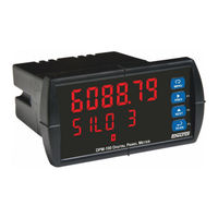
BINMASTER DPM-100 Instruction Manual (68 pages)
Digital Panel Meter Modbus Display
Brand:
BINMASTER
| Category:
Monitor
| Size: 4 MB
Table of Contents
Table of Contents
3
Introduction
6
Ordering Information
7
Specifications
8
Operating Modes
8
Master & Snooper Settings
8
PV Settings
8
Display Settings
8
Math Functions
9
General
9
Serial Communications
9
Relays
10
Isolated 4-20 Ma Transmitter Output
10
USB Connection
11
On-Board Digital Input (F4)
11
Scanview
11
Compliance Information
12
Safety
12
Electromagnetic Compatibility
12
Safety Information
12
Installation
12
Unpacking
12
Figure 1. 1/8 DIN Panel Cutout Dimensions
13
Figure 2. Panel Mounting Details
13
Figure 3. Scanner Dimensions - Side View
13
Figure 4. Scanner Dimensions - Top View
13
Panel Mounting Instructions
13
Mounting Dimensions
13
Installation Overview
13
Scanview Software
14
Scanview Installation
14
Figure 10. PD6088-#H7-BM Connectors Label
15
Figure 9. PD6088-#H5-BM Connectors Label
15
Figure 8. PD6088-#H4-BM Connectors Label
15
Figure 7. PD6088-#H3-BM Connectors Label
15
Figure 6. PD6088-#H2-BM Connectors Label
15
Figure 5. PD6088-#H0-BM Connectors Label
15
F4 Digital Input Connections
16
Power Connections
16
Serial Communications Connection
16
Serial Communications Connections Table
16
Connections
15
Connectors Labeling
15
Figure 14. F4 Digital Input Connections
16
Figure 13. Three-Wire RS-485 Connection
16
Figure 12. Serial Communications Connections
16
Figure 11. Power Connections
16
4-20 Ma Output Connections
17
Analog Output Power Supply
17
Figure 15. Relay Connections
17
Figure 19. Analog Output Supply Powering Other Devices
17
Figure 18. 4-20 Ma Output Connections
17
Figure 17. Low Voltage DC Loads Protection
17
Figure 16. AC and DC Loads Protection
17
Relay Connections
17
Switching Inductive Loads
17
External Relay, Analog Output, & Digital I/O Connections
18
Interlock Relay Feature
18
Figure 20. Interlock Connections
18
Setup and Programming
19
Overview
19
Front Panel Buttons and Status LED Indicators
19
Display Functions & Messages
20
Menu Navigation Tip
23
Setting Numeric Values
23
Main Menu
23
Serial Communications (Serial)
24
Scanner Mode Selection
25
Operating Modes (Nmode)
25
How to Enable Process Variables (Pvs)
25
Master Mode (Nmastr)
26
Snooper Mode (Snoopr)
27
How to Select 5 or 6-Digit Registers
28
Slave Mode (Slave)
28
Setting up the Scanner (Setup)
29
Setting up the Process Variables (Pvs) (Pv Setup)
30
Setting the Display Decimal Point (Disp . D P)
31
Setting the Float Decimal Point (Flot
31
Scaling the PV Display Values (Scale)
31
Setting up the Displays (Dsplay Setup)
32
Display Line 1 Parameters (Line 1 Dsplay)
32
Display Line 2 Parameters (Line 2 Dsplay)
32
Display Intensity (D-Inty)
32
Display Line 1 Menu (Line 1 Dsplay)
33
Display Line 2 Menu (Line 2 Dsplay)
34
Setting the Tags (Tag) & Units (Units)
35
Application Example 1
35
Setting the Relay Operation (Relay)
38
Relay Setup Menu (Relay Setup)
38
Setting the Relay Action (Act 1)
39
Programming Set and Reset Points
39
Setting Fail-Safe Operation (Failsf)
39
Programming Time Delay (Delay)
39
Relay Action for Communications Break (Break)
39
Time Delay Operation
40
Relay Sampling Operation
40
Relay and Alarm Operation Diagrams
41
High Alarm Operation (Set > Reset)
41
Low Alarm Operation (Set < Reset)
41
High Alarm with Fail-Safe Operation (Set > Reset)
41
Low Alarm with Fail-Safe Operation (Set < Reset)
41
Pump Alternation Control Operation
42
Relay Operation after Communications Break
42
Relay Operation Details
43
Overview
43
Relays Auto Initialization
43
Fail-Safe Operation (Failsf)
43
Front Panel Leds
43
Latching and Non-Latching Relay Operation
43
Non-Latching Relay (Auto)
44
Non-Latching Relay with Manual Reset (A-Nman)
44
Latching Relay (Latch)
44
Latching Relay with Clear (Lt-Clr)
44
Acknowledging Relays
44
Pump Alternation Control Applications (Altern)
45
Setting up the Interlock Relay (Force On) Feature
45
Scaling the 4-20 Ma Analog Output (Aout)
46
Setting up the Password (Pass)
47
Protecting or Locking the Scanner
47
Making Changes to a Password Protected Scanner
47
Disabling Password Protection
47
Advanced Features Menu
48
Advanced Menu Navigation Tips
48
Advanced Features Menu & Display Messages
48
Scan Function (Scan)
50
Manual Control Menu (Contrl)
50
Noise Filter (Filter)
51
Noise Filter Bypass (Bypass)
51
Rounding Feature (Round)
51
Select Menu (Select)
51
Low-Flow Cutoff (Cutoff)
58
Analog Output Source Programming (Aoutpr)
58
Programmable Function Keys User Menu (User)
60
Digital Input Menu (DI 1)
61
Digital Output Menu (Do 1)
61
Reset Menu (Reset)
61
Troubleshooting
62
Diagnostics Menu (Diag)
63
Determining Software Version
63
Reset Scanner to Factory Defaults
63
Testing the Display Leds
63
F4 Operation
64
Maximum/Minimum Readings
64
Scanner Operation
64
Front Panel Buttons Operation
64
Function Keys Operation
64
Factory Defaults & User Settings
65
EU Declaration of Conformity
67
Advertisement
Related Products
BINMASTER Large Modbus DPM-300
BINMASTER DPM-200
BINMASTER DPM-500
BINMASTER DPM-400
BINMASTER Categories
Measuring Instruments
Accessories
Gateway
Security Sensors
Switch
More BINMASTER Manuals
Login
Sign In
OR
Sign in with Facebook
Sign in with Google
Upload manual
Upload from disk
Upload from URL