Table of Contents
Advertisement
Quick Links
DPM-100 Modbus
Instruction Manual
• Modbus
®
RTU Master, Slave, or Snooper Mode
• Poll and Display up to 16 Process Variables
• Large 6-Digit Dual-Line Display, Red LEDs, Sunlight Readable
• 32-Point, Square Root, or Exponential Linearization
• Addition, Difference, Average, Multiplication, Division, Min,
Max, Weighted Average, Ratio, Concentration, & More
• Type 4X, NEMA 4X, IP65 Front
• Input Power Options Include 85-265 VAC or 12-24 VDC
• 2 or 4 Relays + 4-20 mA Output Options
• Multi-Pump Alternation Control
• Free USB Programming Software & Cable*
* Meter powered over USB for configuration only. Scanner will not read values from
connected device while powered via USB connection.
®
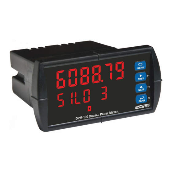
Display
Modbus Display
Advertisement
Table of Contents

Related Manuals for BINMASTER DPM-100


Summary of Contents for BINMASTER DPM-100
- Page 1 ® DPM-100 Modbus Display Instruction Manual Modbus Display • Modbus ® RTU Master, Slave, or Snooper Mode • Poll and Display up to 16 Process Variables • Large 6-Digit Dual-Line Display, Red LEDs, Sunlight Readable • 32-Point, Square Root, or Exponential Linearization •...
- Page 2 Display Instruction Manual Disclaimer The information contained in this document is subject to change without notice. BinMaster makes no representations or warranties with respect to the contents hereof; and specifically disclaim any implied warranties of merchantability or fitness for a particular purpose.
-
Page 3: Table Of Contents
® DPM-100 Modbus Display Instruction Manual Table of Contents Table of Contents ----------------------------------------- 3 Slave Mode (Slave) ------------------------------- 28 Table of Figures ------------------------------------------- 4 Setting Up the Scanner (setup) ----------------- 29 Introduction ------------------------------------------------- 5 Setting Up the Process Variables (PVs) (pv... -
Page 4: Table Of Figures
® DPM-100 Modbus Display Instruction Manual Digital Input Menu (dI 1) ------------------------- 66 Making Changes to a Password Protected Scanner ----------------------------------------------- 50 Digital Output Menu (dO 1) ---------------------- 66 Disabling Password Protection ----------------- 50 Reset Function (reset)----------------------------- 66 4-20 mA Output Calibration ---------------------- 67... -
Page 5: Introduction
LED digits make it easily readable in smoke, dust, fog, and even direct sunlight. As a master, the DPM-100 reads up to 16 slave devices, scales the data from each, displays the result, and operates the internal relays and 4-20 mA output. The DPM-100 in Master mode is capable of polling up to 16 process variables (PVs);... -
Page 6: Ordering Information
4 SPST (Form A) relays PDA1011 Dual 4-20 mA expansion module PDA1044 4 digital inputs & 4 digital outputs (2 may be connected) PDA1485 RS-485 serial adapter - (Included with DPM-100) PDA7485-I RS-232 to RS-422/485 isolated converter PDA7485-N RS-232 to RS-422/485 non-isolated converter PDA8485-I... -
Page 7: Specifications
® DPM-100 Modbus Display Instruction Manual Specifications Except where noted all specifications apply to operation at +25°C. Displays “brEAK” after the Master has Communication Operating Modes Break polled the slave device 3 times and the Master Processes data read from Modbus RTU response timeout has elapsed. -
Page 8: Math Functions
® DPM-100 Modbus Display Instruction Manual Math Functions Max/Min Max/min readings are stored until reset by Display the user or when power to the scanner is Name Math Operation (Examples) Setting turned off. User can reset by front panel (P = Adder, F = Factor) -
Page 9: Relays
® DPM-100 Modbus Display Instruction Manual Relays Isolated 4-20 mA Transmitter Output Rating 2 or 4 SPDT (Form C) internal and/or 4 Output Source PV1-16, math channels C1-4, set points SPST (Form A) external; rated 3 A @ 30 1-8, or manual control mode VDC and 125/250 VAC resistive load;... -
Page 10: Compliance Information
<5%V for 250 periods Interruptions Note: Testing was conducted on DPM-100 meters installed through the covers of grounded metal enclosures with cable shields grounded at the point of entry representing installations designed to optimize EMC performance. Declaration of Conformity available at www.binmaster.com... -
Page 11: Safety Information
® DPM-100 Modbus Display Instruction Manual Safety Information Risk of electric shock or personal injury. Hazardous voltages exist Read complete instructions prior to within enclosure. Installation and installation and operation of the service should be performed only scanner. CAUTION: WARNING! by trained service personnel. -
Page 12: Mounting Dimensions
® DPM-100 Modbus Display Instruction Manual Mounting Dimensions Figure 2. Scanner Dimensions - Side View Figure 3. Scanner Dimensions - Top View... -
Page 13: Connections
The connectors’ label, affixed to the scanner, shows the location of all connectors available with requested configuration. Do not connect any equipment other than BinMaster’s expansion modules, cables, or scanners to the RJ45 M-LINK connector. Otherwise damage will occur to the equipment and the scanner. -
Page 14: Serial Communications Connection
® DPM-100 Modbus Display Instruction Manual Serial Communications Connection Serial communications connection is made to an RJ45 connector labeled M-LINK on the back of the scanner. The Modbus Scanner uses the PDA1485 RS-485 adapter to interface with other Modbus devices and the PDA8485 RS-485 to USB converter or PDA7485 RS-232 to RS-485 converter to connect to a PC. -
Page 15: Serial Communications Connections Table
® DPM-100 Modbus Display Instruction Manual Serial Communications Connections Table The table below shows the terminal connections for 3-wire RS-485 devices. DPM-100 DPM-100 Modbus Modbus Master Snooper Connection Slave Meter Level Gauge PDA1485 PDA1485 PDA8485 RS-485 RS-485 RS-485 Adapter RS-485 Adapter... -
Page 16: Relay Connections
DCLoadProt RC Networks Available from BinMaster RC networks are available from BinMaster and should be applied to each relay contact switching an inductive load. Part number: PDX6901. Note: Relays are de-rated to 1/14 HP (50 watts) with an inductive load. -
Page 17: 4-20 Ma Output Connections
® DPM-100 Modbus Display Instruction Manual 4-20 mA Output Connections Connections for the 4-20 mA transmitter output are made to the connector terminals labeled MA OUT. The 4-20 mA output may be powered internally or from an external power supply. -
Page 18: Setup And Programming
® DPM-100 Modbus Display Instruction Manual Setup and Programming Overview There are no jumpers involved in the scanner setup procedure. Setup and programming is done using ScanView software or through the front panel buttons. After power and signal connections have been completed and verified, apply power to the scanner. -
Page 19: Display Functions & Messages
® DPM-100 Modbus Display Instruction Manual Display Functions & Messages The following table shows the main menu functions and messages in the order they appear in the menu. Display Parameter Description Display Parameter Description t-resp mode Response Time Enter the time allowed for a... - Page 20 ® DPM-100 Modbus Display Instruction Manual Display Parameter Description Display Parameter Description 1234 Byte Order Select big-endian byte order. units Units Units 4321 Byte Order Select little-endian byte formt Format Format (Decimal, Eighths, or order. Sixteenths of an Inch) 2413...
- Page 21 ® DPM-100 Modbus Display Instruction Manual Display Parameter Description Display Parameter Description D off Display off Display Off Relay goes to non-alarm condition when break d-Inty Display Display Intensity detected. Relay turns off Intensity when Communications Break detected. relay Relay Setup...
-
Page 22: Scanview Software
® DPM-100 Modbus Display Instruction Manual ScanView Software The meter can also be programmed using the PC-based ScanView software included with the meter. This software is can be installed on any Microsoft® Windows® (XP/Vista/7/8/10) computer by connecting to the meter’s onboard USB. The meter is powered by the USB connection, so there is no need to wire anything prior to programming the meter, though USB is intended only for meter configuration. -
Page 23: Menu Navigation Tip
® DPM-100 Modbus Display Instruction Manual Menu Navigation Tip • The Up arrow scrolls through the sub-menus within a menu, after the last item it returns to the top menu. Press Enter to step into the menu again or press Up arrow to move to the next menu. -
Page 24: Serial Communications (Serial)
3. When using the M-Link to connect to a Modbus network, the DPM-100 cannot be used as a Master, but can be used as a Snooper or as a Slave. In order to use the DPM-100 as a Master, the scanner must connect to the Modbus Network via the three-wire terminal connector on the back of the scanner. -
Page 25: Scanner Mode Selection
® DPM-100 Modbus Display Instruction Manual Scanner Mode Selection Operating Modes (nmode) The Mode menu is used to select how the scanner is to function: 1. Master: Reads a slave device, scales the data from it, displays the result, and operates the relays and 4-20 mA output. -
Page 26: Master Mode (Nmastr)
® DPM-100 Modbus Display Instruction Manual Master Mode (nmastr) The Master mode contains the PV Number, Poll Time, and Response Timeout menus. PV Number: Enable/disable PVs, select slave ID, function code, register number, data type & byte order. Poll Time: Enter the time interval to poll the slave devices selected. -
Page 27: Snooper Mode (Snoopr)
® DPM-100 Modbus Display Instruction Manual Snooper Mode (Snoopr) The Snooper mode is used to listen to data being transmitted on the bus. Multiple Snoopers can be connected to the RS-485 bus and display any process variable. The same process variable can be displayed in multiple locations. -
Page 28: How To Select 5 Or 6-Digit Registers
® DPM-100 Modbus Display Instruction Manual How to Select 5 or 6-Digit Registers In Master or Snooper Mode, it is possible to select either a five-digit or a six-digit Register Number. Once the operator has enabled a PV, entered a Slave ID, and chosen a Function Code, the scanner will arrive at the Register Number menu (reg. -
Page 29: Setting Up The Scanner (Setup)
® DPM-100 Modbus Display Instruction Manual Setting Up the Scanner (setup) The Setup menu is used to select: 1. PV Setup a. PV Tags b. PV Units c. Format: Decimal point or Feet & Inches d. Decimal Point e. Scale input data 2. -
Page 30: Setting Up The Process Variables (Pvs) (Pv Setup)
® DPM-100 Modbus Display Instruction Manual Setting Up the Process Variables (PVs) (pv setup) Enter the PV Setup menu to set up all the criteria associated with each enabled PV. Once you have selected the desired PV, you can select parameters for each. These include tag, units, format, display decimal point, float decimal point (resolution), and scaling of the input data. -
Page 31: Scaling The Pv Display Values (Scale)
® DPM-100 Modbus Display Instruction Manual Scaling the PV Display Values (sCale) The data that the scanner receives can be scaled to display in engineering units. Input 1 must be less than Input 2; Input 2 must be less than Input 3; etc. (known as monotonic values). Press Enter to save the changes or Menu to exit without saving. -
Page 32: Setting Up The Displays (Dsplay Setup)
® DPM-100 Modbus Display Instruction Manual Setting Up the Displays (dsplay setup) Line 1 Parameters (Line 1 dsplay) The top display (Line 1) can be programmed to display any of the following: Display Parameter Setting Description D pv Display PV... -
Page 33: Display Line 1 Menu (Line 1 Dsplay)
® DPM-100 Modbus Display Instruction Manual Display Line 1 Menu (Line 1 dsplay) Line 2 Setup continues from here. Continues to Relay Setup. Continues to Line 2 Setup. Continues to Line 2 Setup. Continues to Line 2 Setup. Note: For Tag-PVn and Tag-PVn-U, the default settings for PVs are 1,3,5,&7, followed by two... -
Page 34: Display Line 2 Menu (Line 2 Dsplay)
® DPM-100 Modbus Display Instruction Manual Display Line 2 Menu (Line 2 dsplay) Continues to Display Intensity Setup. Continues to Display Intensity Setup. Continues to Display Intensity Setup. Continues to Display Intensity Setup. Note: For Tag-PVn and Tag-PVn-U, the default settings for PVs are 2,4,6,& 8, followed by two... -
Page 35: Setting The Tags (Tag) & Units (Units)
Application Example 1 In this application, we have a system consisting of (4) BinMaster NCR-80 multivariable tank level gauges connected to a DPM-100 displaying feet of product. Register Numbers & Process Variables 32003 –... - Page 36 ® DPM-100 Modbus Display Instruction Manual The following table shows the system setup for the BinMaster NCR-80, one DPM-100 Master, and one DPM-100 Snooper: Parameter DPM-100 DPM-100 Description/Comment Mode Master Snooper PV1 Slave ID Function Code Register PV1 32003 32003...
- Page 37 ® DPM-100 Modbus Display Instruction Manual Parameter DPM-100 DPM-100 Description/Comment PV8 Slave ID Function Code Register PV8 32005 32005 Tank 3 Distance to Product (ft) Data Type Float Float Byte Order 1234 1234 PV9 Slave ID Function Code Register PV9...
-
Page 38: Application Example 2
In this application, we have a system consisting of (4) BinMaster NCR-80 multivariable tank level gauges connected to a DPM-100 displaying feet of product, distance to product in feet, and linear percent. The display readout is shown in linear percent. -
Page 39: Setting The Relay Operation (Relay)
® DPM-100 Modbus Display Instruction Manual Setting the Relay Operation (relay) This menu is used to set up the assignment and operation of the relays. Relay Setup Menu (relay setup) Up Arrow cycles through all available relays. Up Arrow cycles... -
Page 40: Setting The Relay Action (Act 1)
® DPM-100 Modbus Display Instruction Manual Setting the Relay Action (act 1) Operation of the relays is Use Up Arrow relay 1 relay 1 to scroll through programmed in the Action menu. the menu relay relay The relays may be set up for any of choices below. -
Page 41: Relay Action For Communications Break (Break)
® DPM-100 Modbus Display Instruction Manual Relay Action for Communications Break (break) The Scanner will poll the slave device three times before reporting a communications break condition. After the third failure, the Response Timeout timer starts and will determine the actual time to report a PV in break condition. -
Page 42: High Alarm With Fail-Safe Operation (Set > Reset)
® DPM-100 Modbus Display Instruction Manual High Alarm with Fail-Safe Operation Low Alarm with Fail-Safe Operation (Set > Reset) (Set < Reset) Note: Relay coil is energized in non-alarm Note: Relay coil is energized in non-alarm condition. In case of power failure, relay condition. -
Page 43: Relay Sampling Operation
® DPM-100 Modbus Display Instruction Manual Relay Sampling Operation Input Reset Sample Sample Sample Time Time Time Relay When the signal crosses the set point, the relay trips and the sample time starts. After the sample time has elapsed, the relay resets. The cycle repeats every time the set point is crossed, going up for high alarms and going down for low alarms. -
Page 44: Time Delay Operation
® DPM-100 Modbus Display Instruction Manual Time Delay Operation The following graphs show the operation of the time delay function. When the signal crosses the set point, the On time delay timer starts and the relay trips when the time delay has elapsed. -
Page 45: Relay Operation Details
® DPM-100 Modbus Display Instruction Manual Relay Operation Details Overview The relay capabilities of the scanner expand its usefulness beyond simple indication to provide users with alarm and control functions. These capabilities include front panel alarm status LEDs, as well as either 2 or 4 optional internal relays, and/or 4 external relays via expansion modules. -
Page 46: Latching And Non-Latching Relay Operation
® DPM-100 Modbus Display Instruction Manual Latching and Non-Latching Relay Operation The relays can be set up for latching (manual reset) or Relay terminology for following tables non-latching (automatic reset) operation. Terminology Relay Condition Alarm (Tripped) The On and Off terminology does not refer to the status of Normal (Reset) the relay’s coil, which depends on the fail-safe mode... -
Page 47: Acknowledging Relays
® DPM-100 Modbus Display Instruction Manual Acknowledging Relays There are two ways to acknowledge relays programmed for manual reset: 1. Via the programmable F4 digital input assigned to ACK (Default) and connected to a normally open pushbutton wired across F4 and COM. -
Page 48: Setting Up The Interlock Relay (Force On) Feature
® DPM-100 Modbus Display Instruction Manual Setting Up the Interlock Relay (Force On) Feature Relays 1-4 can be set up as interlock relays. To set up the relays for the interlock feature: 1. Access the Setup – Relay – Action menu and set the action to off. -
Page 49: Scaling The 4-20 Ma Analog Output (Aout)
® DPM-100 Modbus Display Instruction Manual Scaling the 4-20 mA Analog Output (Aout) The 4-20 mA analog outputs can be scaled to provide a 4-20 mA signal for any display range selected. The Analog Outputs can be mapped to PVs or Math Channels. To select the channel and source assignments the analog outputs are assigned to, see Analog Output Source Programming on page 64. -
Page 50: Protecting Or Locking The Scanner
® DPM-100 Modbus Display Instruction Manual Pass 1: Allows use of function keys and digital inputs Pass 2: Allows use of function keys, digital inputs and editing set/reset points Pass 3: Restricts all programming, function keys, and digital inputs. Protecting or Locking the Scanner Enter the Password menu and program a six-digit password. -
Page 51: Advanced Features Menu
® DPM-100 Modbus Display Instruction Manual Advanced Features Menu To simplify the setup process, functions not needed for most applications are located in the Advanced Features menu: 1. Scan Mode: Auto or manual; Go on alarm or stop on alarm 2. -
Page 52: Advanced Features Menu & Display Messages
® DPM-100 Modbus Display Instruction Manual Advanced Features Menu & Display Messages Display Parameter Action/Setting Display Parameter Action/Setting No pts sCan Number of Enter Number of Scan Enter Scan menu Points Linearization Points mode Scan Mode Select Auto or Manual... - Page 53 ® DPM-100 Modbus Display Instruction Manual Display Parameter Action/Setting Display Parameter Action/Setting Concen prev Concentration Math Function Previous Previous PV Concentration next Next Next PV math2 Resultant Math Channel Math2 SCAn Scan Scan or pause scan Math operation applied to other math channels...
-
Page 54: Scan Function (Scan)
® DPM-100 Modbus Display Instruction Manual Scan Function (SCan) The Scan menu is used to program the PV scan mode and the scanner’s behavior on alarm condition. The operator is able to scan automatically based on a time parameter, or scan manually with front panel keys or digital inputs. -
Page 55: Noise Filter (Filter)
® DPM-100 Modbus Display Instruction Manual Noise Filter (filter) Most applications do not require changing this parameter. It is intended to help attain a steady display with unsteady (noisy) input data. The field selectable noise filter averages any minor or quick changes in the input data and displays the reading with greater stability. - Page 56 ® DPM-100 Modbus Display Instruction Manual Input Data Conditioning Function Menu (Functn) The Function menu is used to select the input-to-output transfer function applied to the input data: linear, square root, programmable exponent, or round horizontal tank volume calculation. Multi-point linearization (for PV1 and PV2) is part of the linear function selection.
- Page 57 ® DPM-100 Modbus Display Instruction Manual Square Root Function Menu (Square) The square root function is used to calculate flow measured with a differential pressure transmitter. The flow rate is proportional to the square root of the differential pressure. Scale the scanner so that the low input signal (e.g.
- Page 58 ® DPM-100 Modbus Display Instruction Manual Round Horizontal Tank Function Menu (rht) This function is used to calculate volume in a round horizontal tank with flat ends. The volume is calculated based on the diameter and length of the tank. The tank’s dimensions can be entered in inches or centimeters;...
- Page 59 ® DPM-100 Modbus Display Instruction Manual Math Functions (math) The Math menu is used to select the math function that will determine the channels C1-C4 value. These math functions are applied to PVs and other math channels. The results are displayed by selecting Display Channel C (d Ch C) in the Display menu.
- Page 60 ® DPM-100 Modbus Display Instruction Manual Math Function Menu (math) Main Math Channels: Each PV is represented by an underscore. There are 6 lines shown and ten lines hidden. Enter any or all PVs without leaving a space. Any spaces will signal the meter to end the equation there.
- Page 61 ® DPM-100 Modbus Display Instruction Manual Sum Menu (sunm) Difference Menu (dif) Difference Absolute Menu (difAbS) Average Menu (avg) Multiplication Menu (nmulti) Divide Menu (divide) Only two PVs at a time will be used for this function.
- Page 62 ® DPM-100 Modbus Display Instruction Manual Maximum PV Menu (Hi-pv) Minimum PV Menu (Lo-pv) Draw Menu (drauw) Weighted Average Menu (uwAvg) Only two PVs at a time will be used for this Only two PVs at a time will be used for this function.
- Page 63 ® DPM-100 Modbus Display Instruction Manual Low-Flow Cutoff (CutofF) The low-flow cutoff feature allows the scanner to be programmed so that the often unsteady output from a differential pressure transmitter, at low flow rates, always displays zero on the scanner. The cutoff value may be programmed from 0 to 999999.
-
Page 64: Analog Output Source Programming (Aoutpr)
® DPM-100 Modbus Display Instruction Manual Analog Output Source Programming (aoutpr) The 4-20 mA analog outputs can be programmed for source of data, overrange and underrange, absolute maximum and minimum output, and communications break values. They can also be recalibrated. -
Page 65: User Menu (User)
® DPM-100 Modbus Display Instruction Manual User Menu (user) The User menu allows the user to assign the front panel function keys F1, F2, and F3, the digital input F4 (a digital input located on the signal input connector), and up to eight additional digital inputs to access most of the menus or to activate certain functions immediately (e.g. -
Page 66: Digital Input Menu (Di 1)
® DPM-100 Modbus Display Instruction Manual Digital Input Menu (dI 1) If installed, there are up to 8 digital inputs and outputs. There are up to eight Set Points available. Digital Output Menu (dO 1) If installed, there are up to 8 digital inputs and outputs. -
Page 67: 4-20 Ma Output Calibration
(AoutPr)/Calibration (Calib) menu and press Enter. 4. The display will show 4 nmA. The DPM-100 mA output should now be close to 4 mA. Press Enter and the display will show 04.000. Enter the actual value read by the digital mA meter and press Enter. -
Page 68: Troubleshooting
® DPM-100 Modbus Display Instruction Manual Troubleshooting Due to the many features and functions of the scanner, it’s possible that the setup of the scanner does not agree with what an operator expects to see. If the scanner is not working as expected, refer to the recommendations below. -
Page 69: Diagnostics Menu (Diag)
Enter the Diagnostic menu and press the ENTER button to get to the LED Test menu (led t). Press the ENTER button to activate the LED Test. The DPM-100 will cycle through all digits, decimal points, and relay indicators to enable the operator to see that all are functioning properly. Press the ENTER button again to access the Information menu (info). -
Page 70: Scanner Operation
Display Instruction Manual Scanner Operation The DPM-100 scanner is capable of operating as a Modbus Master, Slave or Snooper. As a Slave, the DPM-100 requires connection to a Master device: PLC, DCS, etc. As a Master, the DPM-100 interfaces up to sixteen slave devices and can alternately display their Process Variables. -
Page 71: Factory Defaults & User Settings
® DPM-100 Modbus Display Instruction Manual Factory Defaults & User Settings The following table shows the factory setting for most of the programmable parameters on the DPM-100 scanner. Parameter Display Default Setting Parameter Display Default Setting mode Math, channel Mode... - Page 72 ® DPM-100 Modbus Display Instruction Manual Parameter Display Default Setting Parameter Display Default Setting Pv 4 Dis 2 PV 4 20.000 Relay 4 Display 2 analog assignment Act 4 Out 2 Relay 4 action Automatic Output 2 value 20.000 mA...
- Page 73 ® DPM-100 Modbus Display Instruction Manual This Page Intentionally Left Blank LIM6088BM_B SFT088 Ver 2.010 & up 925-0352 REV 0 02/18...
- Page 74 ® DPM-100 Modbus Display Instruction Manual Jamieson Equipment Company www.jamiesonequipment.com toll free 800.875.0280...
Need help?
Do you have a question about the DPM-100 and is the answer not in the manual?
Questions and answers