Table of Contents
Advertisement
Quick Links
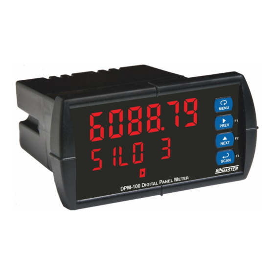
DPM-100 Digital Panel Meter Modbus® Display
Instruction Manual
1/8 DIN Modbus Scanner with NEMA 4X, IP65 Front
•
•
Modbus RS-485 RTU Scanner as Master, Slave, or Snooper
•
On-Board RS-485 Serial Communications Standard
•
Decimal Display
•
Scan up to 16 Modbus Process Variables
Add, Diff, Avg, Multi, Div, Min, Max, Weighted Avg, Ratio, Concentration, & More
•
Dual-Line 6-Digit Display, 0.6" (15 mm) & 0.46" (12 mm)
•
Isolated 24 VDC @ 200 mA Transmitter Power Supply
•
2 or 4 Relays with Interlocking Capability + Isolated 4-20 mA Output Options
•
Free PC-Based, On-Board, ScanView USB Programming Software
•
•
SunBright Display Standard Feature; Great for Outdoor Applications
•
No Assembly Required
•
Operating Temperature Range: -40 to 65°C (-40 to 149°F)
•
Input Power Options: 85-265 VAC / 90-265 VDC or 12-24 VDC / 12-24 VAC
•
Multi-Pump Alternation Control
•
32-Point, Square Root, or Exponential Linearization
Programmable Display, Function Keys & Digital Input
•
External 4-Relay, Dual 4-20 mA Output & Digital I/O Expansion Modules
•
Password Protection
•
3-Year Warranty
•
BINMASTER
Division of Garner Industries
7201 North 98th Street, Lincoln, NE 68507 USA
Tel (402) 278-9102 • Fax: (402) 434-9133
www.binmaster.com
ScanView
USB Install
Advertisement
Table of Contents

Related Manuals for BINMASTER DPM-100


Summary of Contents for BINMASTER DPM-100
- Page 1 DPM-100 Digital Panel Meter Modbus® Display Instruction Manual ScanView USB Install 1/8 DIN Modbus Scanner with NEMA 4X, IP65 Front • • Modbus RS-485 RTU Scanner as Master, Slave, or Snooper • On-Board RS-485 Serial Communications Standard • Decimal Display •...
- Page 2 Generating and saving programming files for • later use Registered Trademarks Once your DPM-100 is programmed the way you want it, All trademarks mentioned in this document are you can wire it up for your application per the instructions the property of their respective owners.
-
Page 3: Table Of Contents
DPM-100 Digital Panel Meter Modbus® Display Instruction Manual Table of Contents Introduction ......................6 Ordering Information ..................7 Specifications ..................... 8 Operating Modes .................... 8 Master & Snooper Settings ................8 PV Settings ..................... 8 Display Settings ..................... 8 Math Functions ....................9 General ...................... - Page 4 DPM-100 Digital Panel Meter Modbus® Display Instruction Manual Display Line 1 Parameters (Line 1 dsplay) ..........32 Display Line 2 Parameters (Line 2 dsplay) ..........32 Display Intensity (d-IntY) ................32 Display Line 1 Menu (Line 1 dsplay) ............. 33 Display Line 2 Menu (Line 2 dsplay) .............
- Page 5 DPM-100 Digital Panel Meter Modbus® Display Instruction Manual F4 Operation ....................64 Maximum/Minimum Readings ..............64 Factory Defaults & User Settings ..............65 EU Declaration of Conformity ................67 Table of Figures Figure 1. 1/8 DIN Panel Cutout Dimensions ........... 13 Figure 2.
-
Page 6: Introduction
4-20 mA output expansion module. 100 displays in decimal format. Various math functions may be applied to the Modbus As a master, the DPM-100 reads up to 16 slave input including addition, difference, absolute devices, scales the data from each, displays the... -
Page 7: Ordering Information
DPM-100 Digital Panel Meter Modbus® Display Instruction Manual Ordering Information DPM-100 Model Numbers 85-265 VAC Power Model Numbers Reorder Number Options Installed PD6088-6H0-BM 348-0029 No options PD6088-6H2-BM 348-0026 2 relays PD6088-6H3-BM 348-0024 4-20 mA output PD6088-6H4-BM 348-0035 4 relays PD6088-6H5-BM 348-0027 2 relays &... -
Page 8: Specifications
DPM-100 Digital Panel Meter Modbus® Display Instruction Manual Specifications Communica- Displays brEAK after the Master has polled tion Break the slave device 3 times and the response timeout has elapsed. The Snooper and Except where noted all specifications apply to Slave modes go into break condition after no operation at +25°C. -
Page 9: Math Functions
DPM-100 Digital Panel Meter Modbus® Display Instruction Manual Math Functions Fuse Required external fuse: UL Recognized, 5 A max, slow blow; up to 6 scanners may share one 5 A fuse. Name Math Operation (Examples) Setting (P = Adder, F = Factor) -
Page 10: Relays
DPM-100 Digital Panel Meter Modbus® Display Instruction Manual Relays Isolated 4-20 mA Transmitter Output Rating 2 or 4 SPDT (Form C) internal and/or 4 SPST (Form A) external; rated 3 A Output Source PV1-16, math channels C1-4, @ 30 VDC and 125/250 VAC resistive load;... -
Page 11: Usb Connection
DPM-100 Digital Panel Meter Modbus® Display Instruction Manual USB Connection ScanView Availability Download directly from scanner or from Function Programming only www.binmaster.com/support/technical/ Compatibility USB 2.0 Standard, Compliant software Connector Type Micro-B receptacle System Microsoft ® Windows ® XP/Vista/7/8/10 Requirements Cable USB A Male to Micro-B Cable Communications USB 2.0 (for programming only) -
Page 12: Compliance Information
DPM-100 Digital Panel Meter Modbus® Display Instruction Manual Compliance Information Safety Information Safety • Read complete instructions prior to installation UL & c-UL Listed USA & Canada and operation of the scanner. UL 508 Industrial Control Equipment UL File Number E160849 Risk of electric shock or personal injury. -
Page 13: Panel Mounting Instructions
DPM-100 Digital Panel Meter Modbus® Display Instruction Manual Panel Mounting Instructions Mounting Dimensions Prepare a standard 1/8 DIN panel cutout - • 3.622" x 1.772" (92 mm x 45 mm). Refer to Figure 1. 1/8 DIN Panel Cutout Dimensions below for more details. -
Page 14: Scanview Software
USB cable. We recommend that the first thing you do after taking the scanner out of the box is connect the DPM-100 to your PC with the provided USB cable. DO NOT apply AC or DC power to the scanner while your PC is connected to the scanner as it will disrupt the USB connection. -
Page 15: Connections
DPM-100 Digital Panel Meter Modbus® Display Instruction Manual Connections All connections are made to removable screw terminal connectors located at the rear of the scanner. • Use copper wire with 60°C or 60/75°C insulation for all line voltage connections. Observe all safety regulations. -
Page 16: Power Connections
DPM-100 Digital Panel Meter Modbus® Display Instruction Manual Power Connections Serial Communications Connections Table Power connections are made to a two-terminal connector labeled POWER on the back of the scanner. The table below shows the terminal connections for The scanner will operate regardless of DC polarity 3-wire RS-485 devices. -
Page 17: Relay Connections
Relay connections are made to two six-terminal connectors labeled RELAY1 – RELAY4 on the back RC networks are available from BinMaster and should of the scanner. Each relay’s C terminal is common be applied to each relay contact switching an only to the normally open (NO) and normally closed inductive load. -
Page 18: External Relay, Analog Output, & Digital I/O Connections
DPM-100 Digital Panel Meter Modbus® Display Instruction Manual External Relay, Analog Output, & Interlock Relay Feature Digital I/O Connections As the name implies, the interlock relay feature reassigns one, or more, alarm/control relays for use The relay, dual analog output, and digital I/O as interlock relay(s). -
Page 19: Setup And Programming
DPM-100 Digital Panel Meter Modbus® Display Instruction Manual Setup and Programming Status Alarm 1-8 indicator Overview Flashing: Relay in manual control There are no jumpers involved in the scanner setup mode procedure. Displays PV to nearest 1/8th or Setup and programming is done using ScanView 1/16th of an inch software or through the front panel buttons. -
Page 20: Display Functions & Messages
DPM-100 Digital Panel Meter Modbus® Display Instruction Manual Display Functions & Messages Display Functions & Messages The following table shows the main menu functions Display Parameter Action/Setting and messages in the order they appear in the menu. Description Byte Order... - Page 21 DPM-100 Digital Panel Meter Modbus® Display Instruction Manual Display Functions & Messages Display Functions & Messages Display Parameter Action/Setting Display Parameter Action/Setting Description Description Byte Order Select big-endian byte Units Units 1234 units order. Format Format (Decimal, fornmt Select little-endian byte...
- Page 22 DPM-100 Digital Panel Meter Modbus® Display Instruction Manual Display Functions & Messages Display Functions & Messages Display Parameter Action/Setting Display Parameter Action/Setting Description Description Display off Display Off Analog output Enter the Analog Output D off Aout scaling menu Display...
-
Page 23: Menu Navigation Tip
DPM-100 Digital Panel Meter Modbus® Display Instruction Manual Menu Navigation Tip Main Menu The main menu consists of the most commonly used The Up arrow scrolls through the sub-menus • functions: Mode, Setup, Serial, and Password. within a menu, after the last item it returns to the top menu. -
Page 24: Serial Communications (Serial)
Master but can be used as a Snooper or as a Slave. In order to use the DPM-100 as a Master, the scanner must connect to the Modbus Network via the three-wire terminal connector on the back of... -
Page 25: Scanner Mode Selection
DPM-100 Digital Panel Meter Modbus® Display Instruction Manual Scanner Mode Selection How to Enable Process Variables (PVs) Operating Modes (nmode) In Master or Snooper Mode, navigate to the PV Number menu and press ENTER. From there, the The Mode menu is used to select how the scanner is... -
Page 26: Master Mode (Nmastr)
DPM-100 Digital Panel Meter Modbus® Display Instruction Manual Master Mode (nmastr) The Master mode contains the PV Number, Poll Time, and Response Timeout menus. PV Number: Enable/disable PVs, select slave ID, function code, register number, data type & byte order. -
Page 27: Snooper Mode (Snoopr)
DPM-100 Digital Panel Meter Modbus® Display Instruction Manual Snooper Mode (Snoopr) The Snooper mode is used to listen to data being transmitted on the bus. Multiple Snoopers can be connected to the RS-485 bus and display any process variable. The same process variable can be displayed in multiple locations. Use the menu below to configure Snooper Mode parameters. -
Page 28: How To Select 5 Or 6-Digit Registers
DPM-100 Digital Panel Meter Modbus® Display Instruction Manual How to Select 5 or 6-Digit Slave Mode (SlaVe) The Slave mode is capable of accepting Short, Long, Registers and Float data types. Refer to the Modbus Register Tables at www.binmaster.com for details of all the In Master or Snooper Mode, it is possible to select predefined parameters. -
Page 29: Setting Up The Scanner (Setup)
DPM-100 Digital Panel Meter Modbus® Display Instruction Manual Setting Up the Scanner (setup) The Setup menu is used to select: PV Setup PV Tags PV Units Format: Decimal point or Feet & Inches Decimal Point Scale input data Display assignment & Intensity... -
Page 30: Setting Up The Process Variables (Pvs) (Pv Setup)
DPM-100 Digital Panel Meter Modbus® Display Instruction Manual Setting Up the Process Variables (PVs) (pV setup) Enter the PV Setup menu to set up all the criteria associated with each enabled PV. Once you have selected the desired PV, you can select parameters for each. These include tag, units, format, display decimal point, float decimal point (resolution), and scaling of the input data. -
Page 31: Setting The Display Decimal Point (Disp . D P)
DPM-100 Digital Panel Meter Modbus® Display Instruction Manual Setting the Display Decimal Point Scale Menu (disp. d p) Decimal point may be set one to five decimal places or with no decimal point at all. Pressing the Up arrow moves the decimal point one place to the right until no decimal point is displayed, and then it moves to the leftmost position. -
Page 32: Setting Up The Displays (Dsplay Setup)
DPM-100 Digital Panel Meter Modbus® Display Instruction Manual Setting Up the Displays Display Line 2 Parameters (Line 2 dsplay) (dsplay setup) The bottom display (line 2) can be programmed to display any of the following: Display Line 1 Parameters Display... -
Page 33: Display Line 1 Menu (Line 1 Dsplay)
DPM-100 Digital Panel Meter Modbus® Display Instruction Manual Display Line 1 Menu (Line 1 dsplay) Note: For Tag-PVn and Tag-PVn-U, the default settings for PVs are 1,3,5, & 7, followed by two underscores, which represent empty PVs. These all can be changed to any enabled PVs. -
Page 34: Display Line 2 Menu (Line 2 Dsplay)
DPM-100 Digital Panel Meter Modbus® Display Instruction Manual Display Line 2 Menu (Line 2 dsplay) Note: For Tag-PVn and Tag-PVn-U, the default settings for PVs are 2,4,6,& 8, followed by two underscores, which represent empty PVs. These all can be changed to any enabled PVs. -
Page 35: Setting The Tags (Tag) & Units (Units)
DPM-100 Digital Panel Meter Modbus® Display Instruction Manual Setting the Tags (tAg) & Units Application Example 1 (units) In this application we have a system consisting of (4) multivariable tank level gauges connected to (2) Each PV can be setup with its own tag and units. See... - Page 36 DPM-100 Digital Panel Meter Modbus® Display Instruction Manual Parameter PD6088 PD6088 Description/ Parameter PD6088 PD6088 Description/ Master Snooper Comment Master Snooper Comment Register Function Tank 1 30003 30003 Code Interface Long Register Tank 3 Data Type Long 30001 30001 integer...
- Page 37 DPM-100 Digital Panel Meter Modbus® Display Instruction Manual Parameter PD6088 PD6088 Description/ Master Snooper Comment PV12 Slave ID Function Code Register Tank 4 30017 30017 PV12 Average Temperature Data Type Long Long integer Binary, Signed Byte Order 1234 1234 Scanner Polling 5.0 sec...
-
Page 38: Setting The Relay Operation (Relay)
DPM-100 Digital Panel Meter Modbus® Display Instruction Manual Setting the Relay Operation (relay) This menu is used to set up the assignment and operation of the relays. Relay Setup Menu (relay setup) Up Arrow cycles through all available relays. Up Arrow cycles... -
Page 39: Setting The Relay Action (Act 1)
DPM-100 Digital Panel Meter Modbus® Display Instruction Manual Setting the Relay Action (act 1) Programming Set and Reset Points Operation of the relays is programmed in the Action menu. The relays may be set up for any of the High alarm indication: program set point above reset following modes of operation: point. -
Page 40: Time Delay Operation
DPM-100 Digital Panel Meter Modbus® Display Instruction Manual Time Delay Operation Relay Sampling Operation The following graphs show the operation of the time delay function. When the signal crosses the set point, the relay trips and the sample time starts. After the sample time has elapsed, the relay resets. -
Page 41: Relay And Alarm Operation Diagrams
DPM-100 Digital Panel Meter Modbus® Display Instruction Manual Relay and Alarm Operation High Alarm with Fail-Safe Operation (Set > Reset) Diagrams The following graphs illustrate the operation of the relays, status LEDs, and ACK button. High Alarm Operation (Set > Reset) Note: Relay coil is energized in non-alarm condition. -
Page 42: Pump Alternation Control Operation
DPM-100 Digital Panel Meter Modbus® Display Instruction Manual Pump Alternation Control Operation Relay Operation After Communications Break When a Master scanner fails to receive a reply from the slave it is called a Communications Break. The relays can be programmed to react to this event by going On, Off, or No Action. After communication is restored the relays are turned off or on, based on their operating mode and their set and reset points, without regard to their prior state. -
Page 43: Relay Operation Details
DPM-100 Digital Panel Meter Modbus® Display Instruction Manual Relay Operation Details Front Panel LEDs The LEDs on the front panel provide status indication Overview for the following: The relay capabilities of the scanner expand its Status Status usefulness beyond simple indication to provide users... -
Page 44: Non-Latching Relay (Auto)
DPM-100 Digital Panel Meter Modbus® Display Instruction Manual Non-Latching Relay (Auto) Latching Relay with Clear (Lt-Clr) In this application, the scanner is set up for automatic In this application, the scanner is set up for manual reset (non-latching relay). Acknowledging the alarm... -
Page 45: Pump Alternation Control Applications (Altern)
DPM-100 Digital Panel Meter Modbus® Display Instruction Manual Pump Alternation Control Setting Up the Interlock Relay Applications (Altern) (Force On) Feature For pump control applications where two or more Relays 1-4 can be set up as interlock relays. To set... -
Page 46: Scaling The 4-20 Ma Analog Output (Aout)
DPM-100 Digital Panel Meter Modbus® Display Instruction Manual Scaling the 4-20 mA Analog There are three analog outputs available. These only display when they are enabled. See graphic below. Output (Aout) The 4-20 mA analog outputs can be scaled to provide * If Installed a 4-20 mA signal for any display range selected. -
Page 47: Setting Up The Password (Pass)
DPM-100 Digital Panel Meter Modbus® Display Instruction Manual Setting Up the Password (pass) Disabling Password Protection To disable the password protection, access the The Password menu is used for programming three Password menu and enter the correct password levels of security to prevent unauthorized changes to twice, as shown below. -
Page 48: Advanced Features Menu
DPM-100 Digital Panel Meter Modbus® Display Instruction Manual Advanced Features Menu Advanced Features Menu & Display Messages To simplify the setup process, functions not needed for most applications are located in the Advanced Advanced Features Menu & Display Messages Features menu:... - Page 49 DPM-100 Digital Panel Meter Modbus® Display Instruction Manual Advanced Features Menu & Display Messages Advanced Features Menu & Display Messages Action/Setting Action/Setting Display Parameter Display Parameter Scale Number of Math2 Function Sum Scale sCale sunm Linearization Points Math2 Function Difference...
-
Page 50: Scan Function (Scan)
DPM-100 Digital Panel Meter Modbus® Display Instruction Manual Scan Function (SCan) Advanced Features Menu & Display Messages The Scan menu is used to program the PV scan Action/Setting Display Parameter mode and the scanner’s behavior on alarm condition. Set Points 1-8... -
Page 51: Noise Filter (Filter)
DPM-100 Digital Panel Meter Modbus® Display Instruction Manual Noise Filter (filter) Select Menu (SELect) Most applications do not require changing this The Select menu is used to select the input data parameter. It is intended to help attain a steady linearization function (linear, square root, display with unsteady (noisy) input data. - Page 52 DPM-100 Digital Panel Meter Modbus® Display Instruction Manual Linear Function Menu (Linear) Scanners are set up at the factory for linear function with 2-point linearization. Up to 32 linearization points can be selected for PV1 and PV2 under the Linear function in the Advanced Features menu. The multi-point linearization can be used to linearize the display for non-linear signals such as those from level transmitters used to measure volume in odd-shaped tanks or to convert level to flow using weirs and flumes with complex exponents.
- Page 53 DPM-100 Digital Panel Meter Modbus® Display Instruction Manual Programmable Exponent Function Menu (prog e) The programmable exponent function is used to calculate open-channel flow measured with a level transmitter in weirs and flumes. The flow rate is proportional to the head height. Scale the scanner so that the low input signal (e.g.
- Page 54 DPM-100 Digital Panel Meter Modbus® Display Instruction Manual Math Functions (nmath) Math Constants (Const) The Math menu is used to select the math function The Math Constants menu is used to set the that will determine the channels’ C1-C4 value. These constants used in the math channel.
- Page 55 DPM-100 Digital Panel Meter Modbus® Display Instruction Manual Math Function Menu (nmath) Main Math Channels: Each PV is represented by an underscore. There are 6 lines shown and ten lines hidden. Enter any or all PVs without leaving a space. Any spaces will signal the meter to end the equation there.
- Page 56 DPM-100 Digital Panel Meter Modbus® Display Instruction Manual Sum Menu (sunm) Difference Menu (dif) Difference Absolute Menu (difAbS) Average Menu (aVg) Multiplication Menu (nmulti) Divide Menu (diVide) Only two PVs at a time will be used for this function.
- Page 57 DPM-100 Digital Panel Meter Modbus® Display Instruction Manual Maximum PV Menu (Hi-pV) Minimum PV Menu (Lo-pV) Draw Menu (drauw) Weighted Average Menu (uwAvg) Only two PVs at a time will be used for this function. Only two PVs at a time will be used for this function...
-
Page 58: Low-Flow Cutoff (Cutoff)
DPM-100 Digital Panel Meter Modbus® Display Instruction Manual Low-Flow Cutoff (CutofF) Analog Output Source Programming (aoutpr) The low-flow cutoff feature allows the scanner to be programmed so that the often unsteady output from a The 4-20 mA analog outputs can be programmed for... - Page 59 Analog Output Calibration Procedure • There is no need to recalibrate the 4-20 mA Wire the DPM-100 4-20 mA output to a current output when first received from the factory. loop that includes a power supply (internal or external 12 to 24 VDC), and the mA input on the •...
-
Page 60: Programmable Function Keys User Menu (User)
DPM-100 Digital Panel Meter Modbus® Display Instruction Manual Programmable Function Keys User Menu (user) The User menu allows the user to assign the front panel function keys F1, F2, and F3, the digital input F4 (a digital input located on the input signal connector), and up to eight additional digital inputs to access most of the menus or to activate certain functions immediately (e.g. -
Page 61: Digital Input Menu (Di 1)
DPM-100 Digital Panel Meter Modbus® Display Instruction Manual Digital Input Menu (dI 1) If installed, there are up to 8 digital inputs and outputs. There are up to eight Set Points available. Digital Output Menu (dO 1) If installed, there are up to 8 digital inputs and outputs. -
Page 62: Troubleshooting
DPM-100 Digital Panel Meter Modbus® Display Instruction Manual Troubleshooting This scanner is a highly sophisticated instrument with an extensive list of features and capabilities. If the front panel buttons are used to program the scanner, it may be a difficult task to keep everything straight. That is why we strongly recommend the use of the free ScanView software for all programming activities. -
Page 63: Diagnostics Menu (Diag)
LED Test menu (led t). Press the ENTER button to activate the LED Test. The DPM-100 will cycle through all digits, decimal points, and relay indicators to enable the operator to see that all are functioning properly. Press the ENTER button again to access the Information menu (info). -
Page 64: Scanner Operation
Instruction Manual Scanner Operation Front Panel Buttons Operation Button Description The DPM-100 Display is capable of operating as a Symbol Modbus Master, Slave or Snooper. As a Slave, the DPM-100 requires connection to a Master device: Press to enter, exit Programming PLC, DCS, etc. -
Page 65: Factory Defaults & User Settings
DPM-100 Digital Panel Meter Modbus® Display Instruction Manual Factory Defaults & User Factory Defaults & User Settings Settings Parameter Display Default Setting Filter The following table shows the factory setting for most Filter of the programmable parameters on the scanner. - Page 66 DPM-100 Digital Panel Meter Modbus® Display Instruction Manual Factory Defaults & User Settings Parameter Display Default Setting Communications break relay 1 Communications break relay 2 Communications break relay 3 Communications break relay 4 Display 1 00.00.00 Dis 1 analog output Output 1 value 4.000 mA...
-
Page 67: Eu Declaration Of Conformity
EU Declaration of Conformity Issued in accordance with ISO/IEC 17050-1:2004. Precision Digital Corporation 233 South Street Hopkinton, MA 01748 USA as the manufacturer, declare under our sole responsibility that the product(s), Model PD6088 & PD6089 ProVu Super Snooper Modbus Scanners to which this declaration relates, is in conformity with the European Union Directives shown below: 2014/35/EU... - Page 68 DPM-100 Digital Panel Meter Modbus® Display Instruction Manual Contact BinMaster Technical Support Call: (800) 278-4241 or (402) 434-9102 Fax: (402) 434-9133 Email: support@binmaster.com Sales Support Call: (800) 278-4241 or (402) 434-9102 Fax: (402) 434-9133 Email: info@binmaster.com Place Orders Email: info@binmaster.com For the latest version of this manual please visit www.binmaster.com...
Need help?
Do you have a question about the DPM-100 and is the answer not in the manual?
Questions and answers