
Bender EDS3090 Manuals
Manuals and User Guides for Bender EDS3090. We have 2 Bender EDS3090 manuals available for free PDF download: Manual
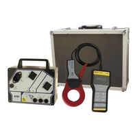
Bender EDS3090 Manual (68 pages)
Portable equipment for insulation fault location for energised and deenergised AC and DC system
Brand: Bender
|
Category: Measuring Instruments
|
Size: 3 MB
Table of Contents
Advertisement

Bender EDS3090 Manual (68 pages)
Portable equipment for insulation fault location for energised and deenergised AC and DC systems
Brand: Bender
|
Category: Test Equipment
|
Size: 11 MB