Sign In
Upload
Manuals
Brands
Barco Manuals
Projector
SLM R12 Plus
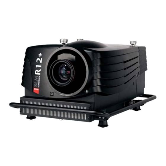
Barco SLM R12 Plus DLP Projector Manuals
Manuals and User Guides for Barco SLM R12 Plus DLP Projector. We have
1
Barco SLM R12 Plus DLP Projector manual available for free PDF download: Service Manual
Barco SLM R12 Plus Service Manual (281 pages)
Brand:
Barco
| Category:
Projector
| Size: 18 MB
Table of Contents
Table of Contents
3
Safety
9
Safety Instructions
9
General Info SLM R12+ P
13
Performances
13
Specifications
14
SLM R12+ P - Parts
15
SLM R12+ P - List of Modules
15
SLM R12+ P - List of Kits
17
SLM R12+ P - List of Lenses
17
SLM R12+ P - Location of the Modules
19
Projector Side - Left
19
Projector Side - Right
20
Projector - Electronic Box
21
Projector - Accessories
29
SLM R12+ P - Location of the Fans
31
Fans - Mounted on Air Outlet
31
Fans - Mounted on Projector Frame
31
Fans - Mounted on the Electronic Box
33
Fans - Mounted on Optical Base
33
Fans - Mounted on Light Engine
34
Fans - Mounted on the Lamp Power Supply
35
Interconnection Diagram
37
IR Transmitter RC-5 Coded R763569
39
General Info
39
Access to the IR Transmitter Board
40
Battery Plug in
40
Technical Info
42
Technical Description
43
Local Keypad & LCD Display
45
General Info
45
Module Replacement
45
Technical Description
46
Status Conditions & Fault Analysis
48
Error List on LCD and INFO Display
48
Error List on INFO Display Only
54
Communication Module R763768
57
General Info
57
Interconnection with CPU
58
Technical Description
59
On Board Connector Pin Assignment
61
On Board Information Display
66
View of the Board
66
Technical Info
66
Error List on INFO Display Only
67
Serial Digital Input Module R7632485
69
General Info
69
Technical Info
69
Signal Input Selection R763850 & R763851
71
General Info
71
Block Diagram Signal Input Selection 1 & 2
72
Technical Description Input Selector 1 & 2
73
Technical Description Input Selector 1
73
General Description
73
Detailed Description
73
Analog Input and Sync Processing
73
DVI Input (Sheet 3/11)
74
Analog to Digital Converter I4 (AD9888KS)
74
DVI Output (See Sheet 3/11)
75
Data Multiplexing (See Sheet 7- 8/11)
75
Sync Switching and Control, I25 (Sheet 9/11)
75
Power Section
76
Technical Description Input Selector 2
76
General Description
76
Analog Input and Sync Processing
76
DVI Input
76
Power Supply
77
Power Diagram for Input Selection Module 1
77
Power Diagram for Input Selection Module 2
80
Digital Decoder R763826
83
General Info
83
Block Diagram Digital Decoder
84
Technical Description
85
General
85
Functional Description
85
Power Supply
86
Digital Inputs Backplane R763378
87
General Info
87
Power Supply Monitoring
87
Interconnection with Communication Interface
89
Power Distribution Backplane R764239
91
General Info
91
Pin Assignment Connectors on Board
92
Euro-Connectors
92
Wire-Connections
93
Wire-Connections to Fans
93
Wire-Connections to Modules
98
Lamp Power Supply R7633705
103
General Info
103
Technical Info
104
Interconnection Diagrams
107
Controls on Board
109
Technical Description LPS-X In/Out R7632113
113
General
113
Functions on the Module
113
EMC Filter - Rush-In Current Limit - Mains Rectifier
114
On-Board SMPS
114
Secondary Circuit of the LPS
115
Measurement of the Lamp Voltage
115
Lamp Current Measurement
115
Boost up Circuit
116
Fan Drive
116
10LAMP_ON Green LED Indication
116
Technical Description LPS-X Processing R7632105
116
General
116
Controller Circuits and Controller Interface Circuits
116
Power Factor Corrector (Sheet 4/5)
118
Primary LPS
120
Pin Assignment Connectors on Board
122
Adjustments on Board
125
Start Pulse Generator (SPG) R763512
127
General Info
127
Technical Info
128
Switch Mode Power Supply (SMPS) R764349
131
Introduction
131
Technical Description
132
Block Diagrams
134
Pin Assignment Connectors on Board
137
Status Conditions/Fault Analysis
139
Temperature & Motor Control Module R764203
141
Introduction
141
Technical Description
141
Pin Assignment Connectors on Board
146
Formatter Interface Board (FIB) R764346
149
Introduction
149
Power Supply
150
Light Engine Connection
152
CPU Module R7638858
155
Introduction
155
Block Diagram CPU
156
Power Supply on Board
157
Functions on Board
157
Interconnection Diagram
158
Pixel Map Processor Module R764115
159
View of the PMP Module
159
Block Diagram PMP
160
Short Technical Description
161
Power Supply
161
Status Conditions / Fault Analysis
163
Infra Red Receiver Module R763261
165
View of the Infra Red Receiver
165
Block Diagram IR Receiver
165
Interconnection Diagram
166
Ambient Temperature Sensor R762790
169
View of the Ambient Temperature Sensor
169
Interconnection Diagram
170
Projector Tilt Switch R764240
171
View of the Projector Tilt Switch
171
Projector Tilting Protection
171
Interconnection Diagram
173
Light Output Sensor R763294
175
View of the Light Output Sensor
175
Technical Info
175
Interconnection with CPU
177
Lamp Info Module R763295
179
View of the Lamp Info
179
Interconnection Diagram
180
Technical Info
181
Maintenance
183
Lens Block
183
Overview of Micro Switches and Motors
183
Disassembling the Lens Block
183
Disassembling a Motor Unit
185
Cleaning/Replacement of the Dust Filters
188
Location of the Dust Filters
189
Cleaning/Replacement of the Dust Filters
189
Dust Filter on the Front Side of the Projector
189
Dust Filters on the Rear Side of the Projector
190
Lamp Replacement
193
Safety Warnings
193
Safety Warnings During Installation
193
Product Care
193
Introduction
194
Content of the Kit
194
Removing the Old Lamp
194
Access to the Lamp Unit
194
Removing the Lamp Unit
195
Inserting the New Lamp Unit
196
Installation of the New Lamp Unit
196
Optical Alignment of the Lamp
198
Reinstalling the Side Panel
199
Re-Convergence
200
Re-Convergence Kit
200
Purpose of the Kit
200
Contents of the Kit
200
Relevant Test Pattern
201
Preparation Projector for Re-Convergence
201
Access to Light Engine
202
Removing the Input Assembly
202
Removing the
202
Removing the Top Cover
203
Disconnection Fans on Light Engine
204
Removing the Prism Cooling Fan
204
Removing the Engine Cooling Fan
205
Electrical Disconnection of the Fans
205
Temporarily Replacement of the Air Channel
206
Removal of the Air Channel
207
Installation of the Service Air Channel (Part of the Kit)
208
Re-Convergence the Light Engine
209
Action of the Convergence Controls
209
Re-Convergence GREEN on RED
211
Location of Controls
211
Re-Converging Green DMD
212
Readjustment of the Plungers
213
Re-Convergence BLUE on RED
215
Location of Controls
215
Re-Converging Blue DMD
216
Readjustment of the Plungers
218
Engine Replacement
219
Safety Instructions
219
General
219
Access to Image Processor Unit
220
Removal of the Input Assembly
220
Removing the Side Panel
220
Removal of the
221
Removing the Lens
221
Removal of the Top Cover
222
Removal of the Lamp Unit
222
Removing the SM Power Supply Module
222
Removal of the Air Channel
224
Removing the Engine
224
Overview Connections Behind Input Box
224
Disconnecting the Formatter and DMD Connections
225
Removing the Disconnected Cables
227
Disconnect the Lens Sensor Cable
228
Disconnect the Shutter
228
Disconnect the Lens Holder Ground Leads
229
Disconnecting the Engine Fans
229
Removing the Engine
230
Installing a New Engine
232
Mounting the Engine
232
Guiding the Cables
234
Connecting the Engine Fans
235
Mounting the Lens Holder Ground Leads
238
Connecting the Shutter
239
Connecting the Lens Sensor
239
Re-Assembling the Projector
240
Mounting the Air Channel
240
Removing the SM Power Supply Module
241
Installation of the Lamp Unit
243
Mounting the Top Cover
244
Reinstalling the Side Panel
245
Lens Installation
246
Mounting the
247
Inserting the Input Panel
247
Replacement of the Light Integration Rod
248
General Info
248
Replacement Procedure
249
Removing the Air Channel Unit
249
Removing the Start Pulse Generator
251
Removal of the Light Integration Rod
252
Installation of the Light Integration Rod
253
Alignment of the Light Integration Rod
254
Select Internal Black Purity Pattern
255
Access to the Controls for the Alignment
256
Focusing the Light Spot
256
Matching the Light Spot to the DMD
257
TM Outline
257
Upgrade with Air Filters
259
Air Filter Upgrade Kit for SLM R12
259
Location of the Dust Filters
259
Contents of the Kit
259
Disassembling the Projector for Cover Replacement
260
Step by Step Actions
260
Disassembling Steps
260
Removing the Lamp Cover
260
Removing the Input Assembly
261
Removing the Rear Cover
261
Removing the Top Cover
262
Removal of the Carrying Handle
264
Removal of the Bottom Cover
265
Reassembling the Projector with Kit Parts
266
Step by Step Actions
266
Reassembling Steps
266
Adaptation of the Safety Cable Tightening Unit
266
Mounting the Bottom Cover with Air Filters
268
Mounting the Carrying Handle Fixation Studs
268
Mounting the Carrying Handle
269
Mounting the Removed Stacking Interlocks
269
Mounting the IR Receiver Unit
270
Mounting the Bottom Cover with Air Filters
272
Overview of the Electrical Diagrams
273
Electrical Diagrams
273
Specifications
275
SLM R12+ P Specifications
275
Index
277
Advertisement
Advertisement
Related Products
Barco SLM R12
Barco SLM R12+ Performer
Barco SLM G10 Performer
Barco SLM G5 Executive
Barco SLM R9+
Barco SLM R6 Executive
Barco SLM G8
Barco SLM G5 Performer
Barco SP4K-C Series
Barco BARCOREALITY SIM 6 MK II + WARP 6
Barco Categories
Projector
Monitor
Projector Accessories
Controller
Medical Equipment
More Barco Manuals
Login
Sign In
OR
Sign in with Facebook
Sign in with Google
Upload manual
Upload from disk
Upload from URL