Sign In
Upload
Manuals
Brands
Barco Manuals
Projector
NW-12
Barco NW-12 Manuals
Manuals and User Guides for Barco NW-12. We have
5
Barco NW-12 manuals available for free PDF download: User Manual, Installation Manual, Option Installation Manual, Product Specifications
Barco NW-12 User Manual (220 pages)
Brand:
Barco
| Category:
Projector
| Size: 26 MB
Table of Contents
Table of Contents
5
Disposal Information
3
1 Introduction
9
About
9
2 Packaging
11
Unpacking
11
3 Installation Guidelines
13
General Installation Guidelines
13
Air Flow Guidelines
14
Air Outlets
14
Air Inlet Obstruction
14
Projector Position
15
Free Space
15
Projector Tilt Range
15
Dimensions: Free Space Around the Projector
16
4 Installation
17
Battery Installation in the RCU
18
Dimensions
18
Lens Installation
19
Lens Formulas
19
Lens Range
19
Battery Installation
19
Shift Capabilities
20
Lens Installation
21
Example of a Horizontal Shift of 100
21
Example of a Vertical Shift of +100% and -25
21
Assembling the Lens, Screening up to the Top Side
22
Lens Interface Plate, Screening up to the Top Side
22
Projector Configuration
23
Lens Assembly Mounting
23
Projector Configurations
23
Positioning the Projector
24
ON-Axis Projector Installation
24
OFF-Axis Projector Installation
25
Connections
26
Power Connection
26
The Front Panel
27
Power Plug Spring System
27
Front Panel Connections
27
Connecting an RGB Signal
28
Input/Output Layers
28
Connecting a Component Video Signal
29
Connecting an RGB Signal
29
Connecting a DVI Signal
30
Connecting a YUV Signal
30
Connecting a DVI Signal to DVI-1
30
Connecting a Composite Video Signal
31
Connecting an S-Video Signal
31
Connecting a DVI Signal to DVI-2
31
Connecting a Source to the Desktop Input
32
Connecting an S-Video Signal
32
Connecting a Desktop Input
32
DVI Output
33
Stereo Connections
33
Stereo Input Connections
34
Stereo Settings
34
Active Infitec
35
Communication
35
Network Connections
35
Crossed Cable Connection
36
How to Connect the Projector
36
Network Settings
37
Connection Via a Hub
37
RS232 Communication
39
Linked CLO
40
Multichannel Installations
40
RS232 Connection
40
Linked Dynacolor
41
Linked Stereo
41
Connections : Linked Stereo
42
Controls Overview
43
Remote Control Unit
43
Local Keypad
43
LCD Display
44
5 Setup
45
Powering up the Projector
45
Power Switch
45
Switch on Sequence
45
Starting up the Projector
46
Standby Status
46
Startup Sequence
47
Setting up the Remote Control Unit Address
48
Setting up the Projector Address (Only if Necessary)
49
Setting up the Orientation
50
Adjusting the Lens
50
Setup the Baud Rate for Serial Communication
52
Preferences
53
Automatic Startup
53
Language Setting
53
Change Password
54
Setup of the Linked Projectors in a Multichannel System
55
6 Getting Started
59
Starting up the Projector
59
Selecting a Source
59
Adjusting the Image
59
7 Advanced
61
Using the Menu
61
Using the Dialog Boxes
62
Source Selection
63
Composite Video
63
S-Video
64
DVI
65
Rgb-Yuv
65
Image
66
Image Settings
66
Setting the Contrast
66
Color (Video Signals Only)
67
Setting the Brightness
67
Gamma
68
Sharpness (Video Signals Only)
68
Tint (NTSC Video Signals Only)
68
Noise Reduction (Only for Video Signals)
69
Phase (RGB Signals Only)
69
Automatic Gain on Video
70
Gain Control on Video
70
Aspect Ratio
71
Manual Gain Control on Video
71
Common Non- Anamorphic Aspect Ratios in (Non-HDTV) DVD Sources
72
Anamorphic Aspect Ratios in (Non-HDTV) DVD Sources
72
Aspect Ratios in Native HDTV DVD Sources
72
Aspect Ratio for WUXGA (1920X1200)
72
What Can be Done
72
Color Temperature
75
Input Balance (RGB Signals Only)
75
Performing Black Input Balance
77
Input Stereo Sync
79
Stereo Swapped Fields
80
Passive Infitec
81
Combining Passive Stereo Inputs into an Active Stereo Image
82
Passive to Active Stereo
82
Passive to Active Stereo Conversion
82
Two DVI Signals Detected
82
Image Files
85
Introduction to Image Files
85
Two Sources Displayed Simultaneously (Bullet); One Source Available (Barco Logo)
85
Load File
86
Forced File Load
87
Auto Image
88
Edit File
89
Which Items Can be Adjusted
90
Save as (Create a Custom File)
92
Copy
93
Rename File
93
Delete
94
Geometry
95
Geometry Files
95
Introduction
95
Geometry File Notation
95
Accessing the Geometry Menu
96
Geometry Distortions
96
The Screen Is Divided in 33X33 Regions
96
Geometry Levels
97
Load
98
Geometry Level Hierarchy
98
Accessing the Geometry Edit Menu
99
Edit
99
Geometry Edit Wizard
100
Geometry Edit Modes
102
Busy Message
102
Editing a Geometry File
104
2X2 Adjustment Points
104
Axis Link
111
Shift Adjustment
114
Transport Delay
116
Geometry: Shift
116
Transport Delay
117
Transport Delay Basic Principle
117
Sharpness
118
Geometry Reset
119
Reset All Levels
119
Restore to a Level
120
Geometry Restore Example : Restoring to a 9X9 Level
121
Rename a Geometry File
122
Copy a Geometry File
123
Delete a Geometry File
124
Lamps
125
Lamp Info
125
Lamp Types
125
Lamp Runtime Warning
126
Lamp Power Mode
127
Constant Light Output (CLO)
128
Constant Light Output Mode
128
CLO Target
129
Linked CLO
130
General
131
Identification
131
Pause
131
Freeze
132
Standby Timer
132
Desktop
133
Display Setup
134
Stereo Display Settings
134
Textbox
134
Introduction
135
Mono Source : Full Screen Synchronous Representation off and Stereo Mode = Always Active
135
Mono Source : Full Screen Synchronous Representation off and Stereo Mode = Auto
135
Mono Source : Full Screen Synchronous Representation on and Stereo Mode = Always Active
135
Stereo Mode
136
Mono Source : Full Screen Synchronous Representation on and Stereo Mode = Auto
136
Stereo Source : Full Screen Synchronous Representation on
136
Stereo Source : Full Screen Synchronous Representation off
136
Full Screen Synchronous Representation
137
Full Screen Synchronous Representation Settings
137
Asynchronous Frequency
139
Menu Bar Position
140
Status Bar Position
140
Slider Box Position
141
Dynacolor
142
Introduction
142
The CIE Chromaticity Diagram
142
The Projector Color Gamut Is Defined by the Triangle Formed by the X, y Coordinates of Red Green and Blue
142
The Color Gamut of each Projector will Differ
143
Common Color Gamut
143
The Common Color Gamut
144
Choosing Dynacolor Sets
146
Enabling Dynacolor
147
Linking Dynacolor
148
Matching Infitec a and Infitec B
149
Changing Color Reproduction
150
Color Triangle: Native Color Gamut of a Device
150
Moving the Desired White Point
151
Black Color Matching
153
Introduction
153
Adjusting the X and y Coordinate of White
153
Black Color Adjustment for Set 1
154
Dark Time
155
Stereo System Setup
155
Opening/Closing Times of the Shutters in Sync with the Blanking Time
155
Shutters Closing too Late And/Or Opening too Early Cause Cross-Talk
156
Shutters Closing too Early And/Or Opening too Late Cause Color Artifacts
156
Invert Stereo
157
Inverted Stereo
158
Stereo Phase
159
Stereo Phase Adjustment
159
Introduction
160
Soft Edge
160
Soft Edge : Purpose
160
Soft Edge Adjustments
161
Soft Edge Basic Principle
161
Soft Edge : Adjustment Points
162
Soft Edge : Points Numbering, Top and Bottom Side Edges
162
Soft Edge : Points Numbering, Left and Right Side Edges
163
Side Soft Edge Zone: Levels
163
Accessing the Soft Edge Menu
164
Soft Edge Edit
164
Soft Edge : Level Hierarchy
164
The Soft Edge Edit Modes
165
The Soft Edge Edit Wizard
165
Creating/Editing a Soft Edge
167
Alpha Planes
174
Black Level
175
Introduction
175
Internal Black Level
176
Black Level : Double Brightness Compensation
176
Beta Planes
177
Blanking
178
Autoimage Setup
179
True Motion Reproduction (TMR)
180
Installation
181
Active Infitec
181
TM Wheel Index
181
Internal Patterns
182
Outline
182
Hatch
182
Color Bars
183
Checkerboard
183
Hgbws
183
H Pattern
183
Convergence
183
Purity
183
How to Select an Internal Pattern
183
Scaled Patterns
184
Scaled Patterns : Geometry
184
Scaled Patterns : Gray Levels
184
Scaled Patterns : Stereo Pattern
185
Formatter Patterns
186
Horizontal Ramp
186
Vertical Ramp
186
Convergence
187
Lfr
187
Stereo Sync out
187
Service
189
Calibration of CLO Sensor
189
Diagnostics
189
Option Key
189
Autoimage
190
Operation Options
190
Warning Messages
190
8 Maintenance
193
Maintenance Timing
193
Visual Checks
194
Cleaning Housing and Mechanical Structure
195
Cleaning the Projection Lens
195
Checking the Cooling Liquid Level
196
Lamp Replacement
196
Container Types
196
Lamp Description
197
Removing the Rear Cover
198
Lamp (Xenon Lamp)
198
Rear Cover: Fixing Screw
198
Removing the Fan Outlet
199
Removing the Lamp
199
Tilt the Back Side of the Rear Cover
199
Pull the Rear Cover Backward
199
Rear Cover Removed
199
Fan Outlet: Fixing Screw
199
Fan Outlet: Lift to Remove
199
Lamp: Fixing Screws
200
Lamp: Removing
200
Lamp: Removed
200
Installing the Lamp
201
Lamp Feet
201
Lamp House: Slider Slot
201
Lamp: Installation
201
Installing the Fan Outlet
202
Lamp: Screws
202
Fan Outlet: Installing
202
Installing the Rear Cover
203
Fan Outlet: Fixing Screw
203
Installing the Rear Cover: Step 1
203
Installing the Rear Cover: Step 2
203
Installing the Rear Cover: Step 3
203
Installing the Rear Cover: Step 4
203
Installing the Rear Cover: Step 5
204
9 Trouble Shooting
205
Error Codes
205
Introduction
205
Overview of the Error Codes
205
LCD Display : Error Display
205
Trouble Shooting through the OSD
207
Basic Troubleshooting Guide
211
Basic Troubleshooting Guide
212
Troubleshooting
212
10 Image Files
213
List of Standard Image Files
213
Index
215
List of Images List of Images
219
List of Images
219
Advertisement
Barco NW-12 User Manual (183 pages)
Brand:
Barco
| Category:
Projector
| Size: 16 MB
Table of Contents
Disposal Information
3
Table of Contents
5
1 Introduction
9
About
9
2 Packaging
11
Unpacking
11
3 Installation Guidelines
13
General Installation Guidelines
13
Air Flow Guidelines
14
Projector Position
15
4 Installation
17
Battery Installation in the RCU
18
Lens Installation
19
Lens Range
19
Lens Formulas
19
Shift Capabilities
20
Lens Installation
21
Projector Configuration
22
Positioning the Projector
23
Connections
26
Power Connection
26
The Front Panel
27
Connecting an RGB Signal
28
Connecting a Component Video Signal
29
Connecting a DVI Signal
30
Connecting a Composite Video Signal
31
Connecting an S-Video Signal
31
Connecting a Computer
32
Connecting a Source to the Desktop Input
32
Communications
33
Network Connections
33
How to Connect the Projector
34
Network Settings
35
RS232 Communication
37
Multichannel Installations
38
Linked CLO
38
Linked Dynacolor
39
Controls Overview
40
5 Setup
43
Powering up the Projector
43
Starting up the Projector
44
Setting up the RCU Address
46
Setting up the Projector Address (Only if Necessary)
46
Setting up the Orientation
47
Adjusting the Lens
48
Setup the Baud Rate for Serial Communication
50
Preferences
50
Language Setting
50
Automatic Startup
51
Change Password
52
Setup of Linked Projectors in a Multichannel System
53
6 Getting Started
57
Starting up the Projector
57
Selecting a Source
57
Adjusting the Image
57
7 Advanced
59
Using the Menu
59
Using the Dialog Boxes
60
Source Selection
61
Composite Video
61
S-Video
62
Rgb-Yuv
62
Image
64
Image Settings
64
Setting the Contrast
64
Color (Video Signals Only)
65
Setting the Brightness
65
Tint (NTSC Video Signals Only)
65
Gamma
66
Sharpness (Video Signals Only)
66
Noise Reduction (Only for Video Signals)
67
Phase (RGB Signals Only)
67
Gain Control on Video
68
Automatic Gain on Video
68
Manual Gain Control on Video
68
Aspect Ratio
69
Color Temperature
73
Input Balance (RGB Signals Only)
73
Performing Black Input Balance
75
Image Files
77
Introduction to Image Files
78
Load File
78
Forced File Load
79
Auto Image
80
Edit File
81
Which Items Can be Adjusted
82
Save as (Create a Custom File)
84
Rename File
85
Copy
85
Delete
86
Geometry
87
Introduction
87
Geometry Files
87
Accessing the Geometry Menu
88
Geometry Distortions
88
Load
91
Edit
92
Accessing the Geometry Edit Menu
92
Geometry Edit Wizard
93
Geometry Edit Modes
95
Editing a Geometry File
97
Axis Link
100
Shift Adjustment
103
Transport Delay
105
Sharpness
107
Geometry Reset
108
Reset All Levels
108
Restore to a Level
108
Rename a Geometry File
110
Copy a Geometry File
111
Delete a Geometry File
112
Lamps
113
Lamp Info
113
Lamp Runtime Warning
114
Lamp Power Mode
115
Constant Light Output (CLO)
116
Constant Light Output Mode
116
CLO Target
117
Linked CLO
118
General
119
Identification
119
Pause
119
Freeze
120
Standby Timer
120
Desktop
121
Display Setup
122
Textbox
122
Full Screen Synchronous Representation
122
Menu Bar Position
124
Status Bar Position
124
Slider Box Position
125
Dynacolor
125
Introduction
126
Dynacolor Adjustment
130
Introduction
130
Calibration for the Standard Mode (for Multiple Projectors)
131
Common Color Values
133
Black Color Matching
134
Introduction
134
Black Color Adjustment for Set 1
135
Soft Edge
136
Introduction
136
Soft Edge Adjustments
137
Accessing the Soft Edge Menu
140
Soft Edge Edit
140
The Soft Edge Edit Modes
141
The Soft Edge Edit Wizard
141
Creating/Editing a Soft Edge
143
Alpha Planes
150
Black Level
151
Introduction
151
Internal Black Level
152
Beta Planes
153
Blanking
154
Autoimage Setup
155
Installation
156
Internal Patterns
156
How to Select an Internal Pattern
157
Scaled Patterns
158
Formatter Patterns
160
Lfr
160
Convergence
161
Service
162
Diagnostics
162
Option Key
162
Calibration of CLO Sensor
163
Operation Options
163
Autoimage
163
Warning Messages
164
8 Maintenance
165
Cleaning the Lens
165
Cleaning the Exterior of the Projector
165
Regular Check of the Cooling Liquid Level
165
9 Trouble Shooting
167
Error Codes
167
Introduction
167
Overview of the Error Codes
167
Trouble Shooting through the OSD
169
Basic Troubleshooting Guide
173
Troubleshooting
174
10 Image Files
175
List of Standard Image Files
175
Glossary
177
Index
179
List of Tables
183
Barco NW-12 Installation Manual (54 pages)
Engine Kit
Brand:
Barco
| Category:
Engine
| Size: 26 MB
Table of Contents
Table of Contents
5
1 Safety Instructions
7
2 Kit Description
9
Kit Content
10
3 Engine Replacement
11
Cable Basket: Push the Joggle
12
Cable Basket: Lift, then Pull to Remove It
12
Rear Cover: Fixing Screw
12
Removing the Rear Cover
12
Tilt the Back Side of the Rear Cover
13
Pull the Rear Cover Backward
13
Rear Cover Removed
13
Top Cover: Front Screws
13
Top Cover: Left Screw
13
Top Cover: Right Screw
13
Removing the Top Cover
13
Top Cover: Lift to Remove
14
Vertical Shift: Nominal Position
14
Horizontal Shift: Nominal Position
14
Procedure to Shift the Lens Holder to Nominal Position
14
Engine Fan Cover 1: Fixing Screws
15
Engine Fan Cover: Lift to Remove
15
Removing the Engine
15
Engine Fan Cover 2: Fixing Screws
16
Removing the Engine Controller Frame Assembly
16
Engine Controller Frame Assembly: Fixing Screws
17
Fan Unit 2: Fixing Screws
17
Removing Fan Unit 2
17
Screws Fixing the Engine to the Lens Holder
18
Engine: Location of the Fixing Screws 1 and 2 (Top View)
18
Engine: Fixing Screw 1 (3D View)
19
Engine: Fixing Screw 2 (3D View)
19
Engine: Connectors
19
Power Cables Connected to the Preformatter Board
20
Replacing with the New Engine
20
Engine: Alignment Pin 1
21
Installing the New Engine
21
Lens Holder: Two Screws Fixing the Lens Holder to the Inside Frame
22
Lens Holder: Screw Fixing the Lens Holder to the Outside Frame
22
Engine: Fixing Screws to the Projector
23
Engine: Fixing Screws to the Lens Holder
23
Lens Holder: Two Screws Fixing the Lens Holder to the Inside Frame
24
Lens Holder: Screw Fixing the Lens Holder to the Outside Frame
24
Engine: Connectors
24
Fan Unit 2: Fixing Screws
25
Installing the Fan Unit 2
25
Engine Controller Frame Assembly: Fixing Screws
26
Installing the Engine Fan Cover 2
26
Engine Fan Cover 2: Fixing Screws
27
Engine Fan Cover 1: Installing
27
Engine Fan Cover 1: Fixing Screws
28
Top Cover
28
Installing the Top Cover
28
Top Cover: Left Screw
29
Top Cover: Right Screw
29
Top Cover: Front Screws
29
Installing the Rear Cover: Step 1
29
Installing the Rear Cover: Step 2
30
Installing the Rear Cover: Step 3
30
Installing the Rear Cover: Step 4
30
Installing the Rear Cover: Step 5
30
Folding Mirror: Examples of Misalignment
30
Alignment Procedure
30
Folding Mirror: Adjustment Screws
31
Integrating Rod Alignment
31
Integrating Rod: Misaligned (Rotation)
32
Integrating Rod: Misaligned (Shift + Rotation)
32
Integrating Rod: Rotated and in Focus
32
Integrating Rod Rotation Alignment
32
Integrating Rod: Securing Screws a and B
33
Integrating Rod: Lift Screw a
33
Integrating Rod: Lower Screw a
33
Integrating Rod: Well Aligned (Rotation)
33
Integrating Rod: Securing Screws a and B
34
Integrating Rod: Rotate
34
Integrating Rod: Rotated and out of Focus
34
Integrating Rod: Shift
35
Integrating Rod: Rotated and in Focus
35
Integrating Rod: Rotate
35
Integrating Rod: Well Aligned (Rotation)
35
Cold Mirror
36
Cold Mirror: Counter Nuts Released
36
Cold Mirror: Adjusting Nuts
36
Scheimpflug: Parallel Planes
37
Scheimpflug: Tilted Lens Results in Tilted Focus Plane
38
Scheimpflug Adjustment Points
38
Scheimpflug Adjustment
39
Scheimpflug Adjustment
40
Adjusting the Scheimpflug
40
Scheimpflug Adjustment: Shims Can be Inserted between 1 and 2
41
Convergence Error (Red Is Misaligned)
42
Convergence Adjustment
42
Formatter: Securing Screws
43
Formatter: Securing Screws (Simplified)
43
Simplified Representation of the Controls of the Red Formatter
43
Functionality of the Convergence Controls
44
Convergence Controls of the Red Channel: Access
44
Green Formatter: Securing Screws
45
Formatter: Securing Screws (Simplified)
45
Simplified Representation of the Controls of the Green Formatter
45
Convergence Controls of the Green Channel
45
Functionality of the Convergence Controls
46
Green Formatter: Convergence Control Screws
46
Adjusting the Convergence
46
Convergence Pattern: Red on Blue
47
Securing Screws of the Formatter Support Plate
47
Convergence Controls of the Red Formatter
48
Securing Screws of the Formatter Support Plate
48
Convergence Pattern: Green on Blue
49
Controls of the Green Formatter
49
Convergence Pattern: Red on Green
49
Example of a Red on Blue Convergence Adjustment
50
Example of Convergence Correction
50
Index
51
List of Images List of Images
53
List of Images
53
Advertisement
Barco NW-12 Option Installation Manual (35 pages)
PMP kit
Brand:
Barco
| Category:
Projector
| Size: 8 MB
Table of Contents
Disposal Information
3
Table of Contents
5
1 Safety Instructions
7
Safety During Kit Installation
7
2 PMP Kit
9
Introduction
9
Kit Description
9
Kit Installation (Overview)
9
3 Kit Installation (Detailed)
11
Making a Backup of the PMP to be Replaced
11
Replacing the Faulty PMP
11
Removing the Input Module
11
Removing the PMP
12
Installing the PMP
14
Installing the Input Module
16
Restoring the Backup
17
Upgrade the Projector to the Desired Software Version
17
Backup and Restore Data
19
Connecting to the Projector through Projector Support
19
Making a Backup of the Projector's Key Data
22
Restoring a Set of Key Data
25
Index
35
Barco NW-12 Product Specifications (3 pages)
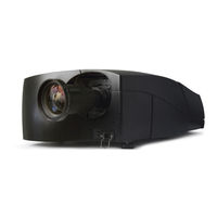
3D stereo, networkcentric, 12,000 lumens, WUXGA, threechip DLP projector
Brand:
Barco
| Category:
Projector
| Size: 0 MB
Advertisement
Related Products
Barco Galaxy NH-12
Barco Galaxy NW-7
Barco Galaxy NW R9040411
Barco Galaxy NW R9240411
Barco Galaxy NW R9040406
Barco Galaxy NW R9240406
Barco Njord
Barco NGS-D200
Barco Nio E-3620
Barco Nio Color 5MP
Barco Categories
Projector
Monitor
Projector Accessories
Controller
Medical Equipment
More Barco Manuals
Login
Sign In
OR
Sign in with Facebook
Sign in with Google
Upload manual
Upload from disk
Upload from URL