Sign In
Upload
Manuals
Brands
Banner Manuals
Accessories
IVU2PTG606
Banner IVU2PTG606 Manuals
Manuals and User Guides for Banner IVU2PTG606. We have
1
Banner IVU2PTG606 manual available for free PDF download: Instruction Manual
Banner IVU2PTG606 Instruction Manual (241 pages)
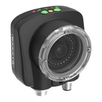
iVu Plus TG and Color Gen2 Image Sensors
Brand:
Banner
| Category:
Accessories
| Size: 12.97 MB
Table of Contents
Table of Contents
2
1 Product Description
6
Models
6
2 Overview
8
Features and Indicators
8
Vision Manager Software
8
Demo Mode
8
Sensor Types
9
Multiple Sensors
9
Multiple Inspections
9
Imager Resolution
9
Communication Channels
10
3 Specifications and Requirements
11
Specifications
11
PC Requirements
11
Dimensions
12
Using Ivu Gen1 and Gen2 Devices in the same Application
15
Banner Engineering Corp. Software Copyright Notice
16
Additional Copyright Information
16
Trademarks
16
4 Installation Instructions
17
Mount the Ivu
17
Cable Connections
17
Installing a Filter on an Ivu
18
Install the Software
19
5 Vision Manager
20
Connect to the Sensor
20
Home Screen
21
Sensor Neighborhood
21
Sensor Maintenance
23
Emulators
24
About
25
Sensor Screen
25
6 Getting Started
26
Setting up an Inspection
26
Acquiring a Good Image
26
Add a New Inspection
28
Trigger Modes
29
Change the Running Inspection
29
7 Device Home Screen
31
Display Mode
31
Image with Annotations
31
Image Without Annotations
31
Inspection Statistics
32
8 Device Main Menu
34
Icon Reference
35
Action Icons
35
Display Icons
37
Communications Log Icons
37
9 Device Inspection Menu
38
Sensors Menu
38
Area Menu
38
Blemish Menu
39
Match Menu
41
Sort Menu
42
Average Color Menu
43
Color Compare Menu
46
Color Area Menu
47
Motion Menu
48
Number of Edges
49
Sensitivity
49
Rotation
49
Teach ROI Type
49
Percent Match
49
Rotation Range
50
Edit Pattern
50
Advanced
50
Timeout
50
Properties Menu
50
Inspection Name
50
Inspection ID
51
Motion
51
Stored Inspections Menu
51
Select
51
Add New
51
Startup
52
Delete Inspections
52
Set Name/ID
52
10 Device Imager Menu
53
Auto Exposure
53
Exposure
53
Gain
53
Trigger
54
Focus
54
Strobe Menu
55
External
55
Internal
55
FOV (Field of View)
55
Adjust the Field of View (Grayscale Models Only)
56
Resolution
56
White Balance
57
11 Device System Menu
58
Mode
58
System Configuration Menu
58
Save to USB
59
Load from USB
59
Reset to Defaults
59
System Information
59
Lock Device
59
Communications Menu
60
Ethernet I/O
60
Serial I/O
61
Industrial Ethernet
61
Command Channel
65
Data Export Menu
66
Image Export
68
Discrete I/O Menu
69
Input Polarity
69
Input Pullup
70
Output Type
70
Output 1, 2, and 3
70
Display Settings
71
Fail Hold Time
72
LCD Timeout
72
Touch Calibration
72
Advanced
72
Reboot Sensor
72
Firmware Update
73
Ivu Trigger, Remote Teach, and I/O Waveforms
73
PNP (Low-To-High) Trigger and Remote Teach Input Waveforms
73
NPN (High-To-Low) Trigger and Remote Teach Input Waveforms
73
Ivu Output Waveforms
74
12 Device Logs Menu
76
Inspection Logs Menu
76
View Logs
76
Setup
77
System Logs
77
Communication Logs Menu
78
Industrial Ethernet Log
78
Command Channel Log
78
Image Export Log
79
13 Configuring Sensors
80
Setting the Trigger
80
Configuring an Area Sensor
80
Configuring a Blemish Sensor
82
Configuring a Match Sensor
84
Remote Teach
87
Configuring a Sort Sensor
87
Configuring Motion
89
Number of Edges
89
Sensitivity
89
Rotation
89
Teach ROI Type
90
Percent Match
90
Rotation Range
90
Timeout
90
Configuring an Average Color Sensor
90
Configuring a Color Compare Sensor
91
Configuring a Color Area Sensor
93
Configuring Multiple Sensors in the Inspection
94
Configuring a Mask
96
14 Communications Guide
98
Ivu Plus Communication Summary of Ethernet and Serial
98
Communication Channels
98
Industrial Ethernet
98
Command Channel
98
Data Export
99
Image Export
101
Enabling Communications
101
Setting up Ethernet Communications
101
Setting up Serial Communications
106
Testing and Troubleshooting Ivu Communications
108
Understanding the Communication Log
108
Ethernet I/O
109
Serial I/O
109
Command Channel Primer
111
Command Channel Commands
111
Conventions Used for Examples
112
Examples
112
Command Channel Reference
113
Multiple Sensors in an Inspection
123
Command Channel Command Status Register
123
Command Channel Error Codes
123
Ivu Discovery Protocol
125
UDP Usage
125
Packet Format
125
Message Flow
128
15 Industrial Ethernet Overview
131
Device Setup
131
Set IP Address
131
Set the Industrial Ethernet Protocol
131
Set Trigger Mode
131
Supported Functions
131
Ivu Input Values
131
Ivu Output Values
132
Ivu Operation
132
General Command Execution
133
Ethernet/Ip
133
Inputs to the Ivu (Outputs from the PLC)
134
Outputs from the Ivu (Inputs to the PLC)
134
Multiple Sensors Mapping Options
135
Input and Output Flags Bits
140
Configuration Assembly Object
140
Data Formats
140
Minimum Requested Packet Interval (RPI) Value
140
Ivu Plus TG and Color Gen2 Image Sensors EDS File Installation in Controllogix Software
141
Rslogix5000 Configuration
146
Modbus/Tcp
152
Ivu Input Values
154
Ivu Output Values
154
Multiple Sensors Mapping Options
154
Input and Output Bits
160
PLC5, SLC500, and Micrologix (PCCC)
160
Configuration
160
Inputs to Ivu (Outputs from PLC)
164
Outputs from Ivu (Inputs to PLC)
164
Multiple Sensors Mapping Options
165
Input and Output Flags
169
Profinet
170
General Station Description (GSD) File
170
Ivu PROFINET IO Data Model
170
Configuration Instructions
183
Sample Timing Diagrams
204
Command Channel Command Status Register
206
Diagnostic Guide
206
Ethernet Diagnostics
206
Networking and TCP/IP Diagnostics
207
Industrial Protocols Troubleshooting
209
Additional Information
214
Ivu Command Channel Commands (Ivu Command Channel over Industrial Ethernet)
214
16 Troubleshooting
219
LED Indicator Troubleshooting
219
Errors
219
Warnings
219
How to Round-Trip Debug Using the Emulator
219
How to Debug Using Inspection Logs
220
How to Debug Using Bitmap Files
220
Vision Manager Error Codes
221
17 Accessories
230
Power Cable - Required
230
Remote Display-Required for Setup (Remote Display Models Only)
230
RDM35 Remote Display Accessory Kit
230
Ethernet Cable Options
231
USB Cable - Optional
231
USB Flash Drive - Optional
231
Brackets
232
Micro Video Lens Accessories
233
Micro Video Lens Models
233
Micro Video Lens Filters - Optional
233
C-Mount Lens Accessories
233
C-Mount Lens Models
233
C-Mount Lens Enclosure Models
234
C-Mount Lens Filters - Optional
234
18 Product Support and Maintenance
235
Product Support
235
Maintenance
235
Clean the Ivu
235
Update the Ivu Firmware
235
How to Set or Modify a Device Name Using the Emulator
236
How to Reset the Device Password
237
Contact Us
237
Banner Engineering Corp Limited Warranty
237
FCC Part 15 and CAN ICES-3 (A)/NMB-3(A)
238
Advertisement
Advertisement
Related Products
Banner IVU2PTG604
Banner IVU2PTG612
Banner IVU2PTG608
Banner IVU2PTG625
Banner IVU2PTG616
Banner IVU2PTGX06
Banner IVU2PTGR04
Banner IVU2PTGB04
Banner IVU2PTGW06
Banner IVU2PTG916
Banner Categories
Accessories
Controller
Gateway
Security Sensors
Measuring Instruments
More Banner Manuals
Login
Sign In
OR
Sign in with Facebook
Sign in with Google
Upload manual
Upload from disk
Upload from URL