Sign In
Upload
Manuals
Brands
Bailey Manuals
Control Unit
infi 90 IMASI03
Bailey infi 90 IMASI03 Manuals
Manuals and User Guides for Bailey infi 90 IMASI03. We have
1
Bailey infi 90 IMASI03 manual available for free PDF download: Instruction
Bailey infi 90 IMASI03 Instruction (105 pages)
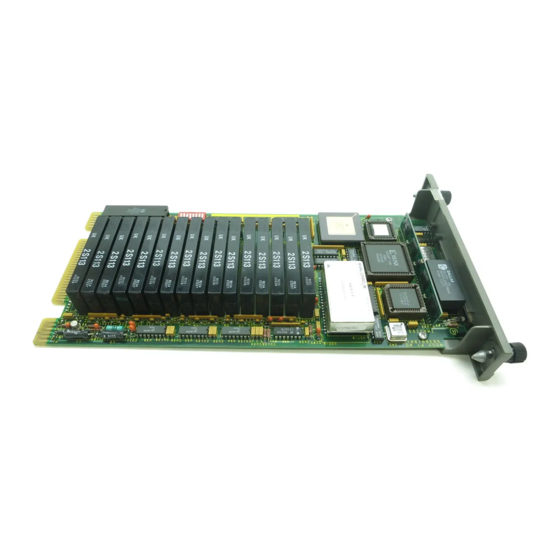
Universal Analog Input Slave Module
Brand:
Bailey
| Category:
Control Unit
| Size: 1 MB
Table of Contents
Table of Contents
7
Section 1 - Introduction
11
Overview
11
Intended User
11
Module Description
11
Features
12
INFI 90 Communication Levels
12
Instruction Content
14
How to Use this Manual
14
Glossary of Terms and Abbreviations
15
Reference Documents
17
Nomenclature
17
Specifications
18
Section 2 - Description and Operation
22
Introduction
22
Functional Operation
22
Block Diagram
22
Isolation Amplifier
23
Input Multiplexer (MUX)
23
Analog to Digital Conversion
23
IMASI03 Functional Block Diagram
23
Microcontroller and Memory
24
Cold Junction Reference
24
Switch Settings
25
On-Board Indicators
25
Slave Expander Bus
25
Data Values
26
Function Codes
26
Slave Expander Bus Interface
26
Termination Units
26
Automatic Adjustments and Corrections
27
Input Processing
27
Point Value Calculation
27
Cold Junction Compensation
28
Input Calibration
28
Lead Wire Resistance Adjustment
28
Engineering Units Conversion
29
User Gain and Offset Adjustment
29
Automatic Calibration
30
Field Calibration
30
Input Calibration
30
Security and Integrity Checks
30
Diagnostics Run on Reset
30
Alarm and Exception Reporting
31
Diagnostics Run During Normal Operation
31
Diagnostics Run in Diagnostic Mode
31
Expander Bus Communication Security
31
Open Input Detection
31
On-Line Configuration
32
Logic Power
32
Section 3 - Installation
33
Introduction
33
Special Handling
33
Unpacking and Inspection
33
Setup/Installation
34
Address Selection Switch (SW1)
34
Address Select Switch (SW1)
34
Configuring Inputs
35
Address Switch Settings (S1)
35
Setup
36
IMASI03 Jumper Configurations
36
IMASI03 Jumpers Used for each Channel
36
IMASI03 Jumper Locations
36
Termination Module/Unit Configuration
37
Physical Installation
37
Wiring Connections and Cabling
37
Cable Connections
38
Wiring
38
NIAI05 to IMASI03 Cable Connections
38
NTAI06 to IMASI03 Cable Connections
39
Section 4 - Configuration and Calibration
40
Introduction
40
Configuring Inputs
40
Configuring Function Codes
40
Calibrating Inputs
41
Field Calibration
42
Field Calibration Instruction
45
Test Equipment Required
45
Individual Channel Calibration
46
Section 5 - Operating Procedures
50
Introduction
50
Start-Up
50
Operation
50
On-Board Indicators
50
On-Board Indicators
51
Alarm and Exception Reporting
52
Problem Reports
52
Section 6 - Troubleshooting
52
IMASI03 Error Types
53
Error Messages and Corrective Actions
55
Input Channel Status
55
Slave Errors
55
Module Status (Byte 3) Error Codes
55
Error Example
57
Module Functional Tests
57
Test Equipment Requirements
57
Halt - Display Error
58
Switch SW1 Settings
58
Switch SW1 Settings, Operating Modes and Error Messages
58
Continue - Do Not Display Error
59
Dipswitch Configurable Diagnostics
59
Test Procedure
59
Dipswitch Test
59
All Tests Mode
60
Slave Expander Bus Interface Test
60
Test Procedure
60
Module Pin Connections
61
P1 Power Pin Connections
61
P2 Expander Bus Connections
61
P3 Input Signal Pin Connections
62
Section 7 - Maintenance
63
Introduction
63
Maintenance Schedule
63
Section 8 - Repair/Replacement Procedures
64
Introduction
64
Module Repair/Replacement
64
Section 9 - Support Services
65
Introduction
65
Replacement Parts and Ordering Information
65
Training
65
Technical Documentation
65
Cold Junction Reference Input
66
Introduction
66
Appendix A - Niai05 Termination Module Configuration
67
Configuring Inputs
67
NIAI05 Input Types
67
NIAI05 Input Type Descriptions
68
Configuring Inputs
69
Configuring Inputs
70
Jumper Locations for Revision a Hardware NIAI05
70
Jumper Locations for Revision B Hardware NIAI05
71
Terminal Assignments for Revision a Hardware NIAI05
72
Terminal Assignments for Revision B Hardware NIAI05
72
Typical Input Circuit for Revision a Hardware
73
Typical Input Circuit for Revision B Hardware
74
Field Input Termination Examples for Revision a Hardware NIAI05
75
Field Input Termination Examples for Revision B Hardware NIAI05
75
Revision a Hardware IMASI03 Input Examples
76
Revision B Hardware IMASI03 Input Examples
77
Cable Connections for Revision a and B Hardware NIAI05
78
Appendix B - Ntai06 Termination Unit Configuration
79
NTAI06 Input Types
80
NTAI06 Input Type Descriptions
80
Jumper Locations and Terminal Assignments for Revision a Hardware NTAI06
82
Jumper Locations and Terminal Assignments for Revision B Hardware NTAI06
83
Typical Input Circuit for NTAI06
84
Field Input Termination Examples for Revision a and B Hardware NTAI06
85
IMASI03 Input Examples
86
Cable Connections for NTAI06
87
Cold Junction Reference Input
88
Appendix C - Function Code Definitions
88
Introduction
88
Enhanced Analog Slave Definition Function Code
89
FC 215 Outputs
89
Remote Cold Junction Compensation
91
Enhanced Analog Input Definition Function Code
92
FC 216 Outputs
92
FC 216 Specifications
93
FC 216 Input Signal Types
94
Enhanced Calibration Command Function Code
96
FC 217 Outputs
97
FC 217 Output Descriptions
98
FC 217 Specifications
99
Advertisement
Advertisement
Related Products
Bailey infi 90 IMASI02
Bailey Infi 90 IMAOM01
Bailey Infi 90 IMCPM02
Bailey Infi 90 IMDSM05
Bailey Infi 90 IMFBS01
Bailey Infi 90 IMDSO02
Bailey Infi 90 IMLMM02
Bailey Infi 90 IMQRC01
Bailey Infi 90 IMRIO02
Bailey INFI 90 IMCOM03
Bailey Categories
Control Unit
Motorhomes
Lighting Equipment
Recording Equipment
Controller
More Bailey Manuals
Login
Sign In
OR
Sign in with Facebook
Sign in with Google
Upload manual
Upload from disk
Upload from URL