Sign In
Upload
Manuals
Brands
Bailey Manuals
Control Unit
infi 90 IMASI02
Bailey infi 90 IMASI02 Manuals
Manuals and User Guides for Bailey infi 90 IMASI02. We have
1
Bailey infi 90 IMASI02 manual available for free PDF download: Instruction
Bailey infi 90 IMASI02 Instruction (43 pages)
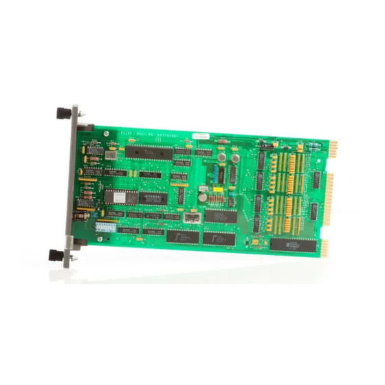
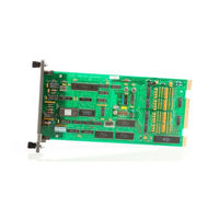
Analog Slave Input Module
Brand:
Bailey
| Category:
Control Unit
| Size: 1 MB
Table of Contents
Table of Contents
7
Section 1 - Introduction
10
Overview
10
Infi 90 Communication Levels
10
Ntended User
11
Module Description
11
Features
11
How to Use this Manual
11
Reference Documents
13
Nomenclature
13
Specifications
14
Glossary of Terms and Abbreviations
15
Section 2 - Description and Operation
16
Introduction
16
Functional Operation
16
Inputs
16
IMASI02 Functional Block Diagram
16
Input Circuit Description
17
Input Circuit Connections
17
Processor and Control Logic
17
IMASI02 Analog Input Circuit
17
A/D Conversion
18
Smart Transmitter Communication
18
MFP Communication
19
STT Terminal Communication
19
Smart Transmitter Communication
19
Command Buffering During Transmitter Communication Failure
19
Data Byte
20
Status Byte
20
Security Byte
20
Communication Lockout Byte
20
Logic Power
21
Slave Expander Bus
21
Universal Slave Expander Bus Interface
21
Section 3 - Installation
22
Introduction
22
Special Handling
22
Unpacking and Inspection
22
Setup/Installation
23
Slave Address Selection Switch (S1)
23
Address Select Switch (S1)
23
Termination Unit/Module Configuration
24
Physical Installation
24
Address Switch Settings (S1)
24
Wiring Connections and Cabling
25
Wiring
25
Cable Connections
25
Fusing
26
Pre-Operating Adjustments
26
IMASI02 Cable Connections and Termination
26
Section 4 - Calibration
27
Introduction
27
Adjusting R22
27
Section 5 - Operating Procedures
28
Introduction
28
Start-Up
28
Operation
28
IMASI02 Adapter Jack Location
29
Section 6 - Troubleshooting
30
Introduction
30
Error Messages and Corrective Action
30
Status Reports
30
Master Module Errors
31
ASI Error Code
31
Smart Transmitter Error Codes
31
Module Pin Connections
32
P1 Power Pin Connections
32
P2 Expander Bus Connections
33
P3 Input Signal Pin Connections
33
Section 7 - Maintenance
34
Introduction
34
Maintenance Schedule
34
Section 8 - Repair/Replacement Procedures
35
Introduction
35
Module Repair/Replacement
35
Section 9 - Support Services
36
Introduction
36
Replacement Parts and Ordering Information
36
Training
36
Technical Documentation
36
Appendix A - Termination Unit (Ntai05) Configuration
37
Introduction
37
Input Circuit for NTAI05
37
Configuring Inputs
38
Terminal Assignments for NTAI05
39
Cable Connections for NTAI05
39
Appendix B - Termination Module (Niai04) Configuration
40
Introduction
40
Configuring Inputs
40
Input Circuit for NIAI04
40
Terminal Assignments for NIAI04
42
Cable Connections for NIAI04
42
Advertisement
Advertisement
Related Products
Bailey infi 90 IMASI03
Bailey Infi 90 IMAOM01
Bailey Infi 90 IMDSI13
Bailey Infi 90 IMDSI14
Bailey Infi 90 IMDSI15
Bailey Infi 90 IMDSI02
Bailey Infi 90 IMDSO15
Bailey Infi 90 IMDSO01
Bailey Infi 90 IMDSO03
Bailey Infi 90 IMSPM01
Bailey Categories
Control Unit
Motorhomes
Lighting Equipment
Recording Equipment
Controller
More Bailey Manuals
Login
Sign In
OR
Sign in with Facebook
Sign in with Google
Upload manual
Upload from disk
Upload from URL