Autonics AiC-D-60MA Manuals
Manuals and User Guides for Autonics AiC-D-60MA. We have 3 Autonics AiC-D-60MA manuals available for free PDF download: User Manual

Autonics AiC-D-60MA User Manual (116 pages)
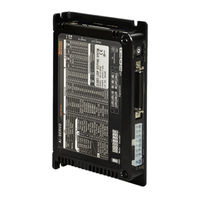
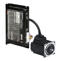
Closed-Loop Stepper System
Brand: Autonics
|
Category: Stepper Machine
|
Size: 4 MB
Table of Contents
Advertisement
Autonics AiC-D-60MA User Manual (98 pages)
Closed-Loop Stepper System
Brand: Autonics
|
Category: Control Unit
|
Size: 3 MB
Table of Contents
Autonics AiC-D-60MA User Manual (88 pages)
Controller Integrated 2-Phase Closed-Loop Stepper Motor System
Brand: Autonics
|
Category: Control Unit
|
Size: 22 MB
Table of Contents
Advertisement