Sign In
Upload
Manuals
Brands
Austro Engine Manuals
Engine
E4P
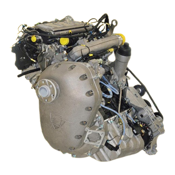
User Manuals: Austro Engine E4P Jet Fuel Piston
Manuals and User Guides for Austro Engine E4P Jet Fuel Piston. We have
3
Austro Engine E4P Jet Fuel Piston manuals available for free PDF download: Maintenance Manual, Operation Manual
Austro Engine E4P Maintenance Manual (658 pages)
Brand:
Austro Engine
| Category:
Engine
| Size: 51 MB
Table of Contents
Table of Contents
7
Introduction
9
General
9
Warning, Cautions and Notes
10
Manual Configuration
10
Chapter Configuration
11
Page Numbering System
11
Figures
11
Revisions
12
List of Revisions
13
List of Included Temporary Revisions
19
List of Service Bulletins Included as Maintenance Procedures
21
Abbreviations
22
General
22
Engine Harness
23
Conversion Factors
24
Conversion Table of Given Torque Values
24
Conversion Table of Given Pressure Values
25
Engine Power Conversions
25
Consumable List
26
General Description of the Engine
27
Transport and Packaging
39
General
39
Packaging
39
Transport
43
Protective Covers
44
Storage and Preservation
45
Storage of a Received Engine
45
Preservation of an Installed Engine
45
Engine Depreservation
47
Engine Storage
48
Return Parts Shipping Instructions
49
Time Limits and Maintenance Check
63
General
63
Words for Special Meanings
64
Claimable Exceed of Maintenance Actions
66
Component Time Limits and Maintenance Requirements
67
Component Time Limits
68
Component Maintenance Requirements
69
Engine Time between Overhaul
70
Scheduled Maintenance Checks
71
Unscheduled Maintenance Checks
76
Performance Deterioration
76
Violation of Temperature Limits
76
Sudden Stoppage Inspection
76
Propeller Strike
76
Lightning Strike
76
High Engine Oil Consumption Inspection
77
Engine Oil System Contaminated
77
Engine Oil Pressure Loss Inspection
77
Inability to Start the Engine
77
Engine over Speed
77
Servicing
82
Engine Oil Servicing
83
Complete a Check of the Oil Level
83
Do a Check of the Gearbox Oil Level
84
Engine Coolant Servicing
84
Electrical Power
89
Electrical System Description
89
Electrical System Installation
90
Alternator
90
Alternator-Regulator Adjustment E4A-91-200-000
91
Paralleling for Twin Engine System E4A-91-200-000
91
Troubleshooting Information
93
General
93
Alternator E4A-91-000-000
95
General
95
Maintenance Procedures
95
Remove the Alternator
95
Install the Alternator
96
Acceptance Criteria for Alternator Bench Tests
98
Inspection of Alternator E4A-91-000-000 and the Carbon Brushes
98
Special Tools
98
Remove the Brush Holder Assembly
98
Visually Examine the Alternator Housing and Pulley
99
Examine the Contact Ring and Brushes
100
Disassemble the Brush Holder Assembly E4A-91-300-000
101
Measure the Length of Carbon Brushes
104
Complete the Brush Holder
104
Install the Brush Holder
106
Functional Check
109
Alternator E4A-91-400-000
116
General
116
Maintenance Procedures
116
Remove the Alternator
116
Install the Alternator
117
Acceptance Criteria for Alternator Bench Tests
120
Inspection of Alternator E4A-91-400-000 and Carbon Brushes
120
Special Tools
120
Remove the Brush the Holder Assembly
120
Visually Examine the Alternator Housing and Pulley
123
Examine the Contact Ring and Brushes
124
Examine the ASSY Brush Holder E4A-91-410-000
125
Measure the Length of Carbon Brushes
125
Install the Brush Holder
126
Functional Check
130
Alternator-Regulator E4A-91-100-000
135
General
135
Adjust the Voltage Regulation E4A-91-100-000
136
Adjust the Alternator Balancing E4A-91-100-000 (Only for Twin-Engine Applications)
136
Replace Alternator-Regulator E4A-91-100-000
136
Standard Procedures
141
General
141
Safetying Methods
141
Standard Torque Values
141
Troubleshooting Information
143
General
143
Safety Wiring
145
General
145
Special Tools
145
Basic Rules
145
Safety Wiring Methods
146
Single Wire Locking
147
Double Wire Locking
148
Examples of Safety Wiring
153
Torque Procedure
157
Installation of Helical Threaded Inserts
161
General
161
Special Tools
164
Install the Threaded Insert
164
Examine the Threaded Insert for Correct Installation
167
Remove the Threaded Inserts
167
Safety the Rotating Threaded Inserts
168
Power Plant
173
General
173
Description
173
Electrical Harness
173
Engine Harness Routing Overview
177
Engine Harness Routing General Instructions
183
Troubleshooting Information
185
General
185
Engine Ground Run
187
General
187
Engine Ground Run Instructions
188
Electrical Harness
190
General
190
Maintenance Procedures
190
Examine the Engine Wiring Harness
190
Examine the Sensors / Actuators
193
Install the Engine Wiring Harness for E4A-90-000-000
194
Install the Engine Wiring Harness E4A-95-000-000 and E4B-95-000-000
213
Engine Fuel and Control
307
General
307
System Description
307
Troubleshooting Information
311
General
311
Engine Fuel Supply
313
General
313
Special Tools
313
Injectors
313
Remove the Injectors
313
Install the Injectors
314
Fuel Return Line
320
Remove the Fuel Return Line
320
Install the Fuel Return Line
320
High Pressure Pump (HPP)
324
Remove the High Pressure Pump (HPP)
324
Install the High Pressure Pump (HPP)
327
Remove the Spur Gear from High Pressure Pump
328
Install the Spur Gear from High Pressure Pump
329
Engine Fuel Control
330
General
330
Low Fuel Pressure Sensor (FPS)
330
Remove the Fuel Pressure Sensor
330
Install the Fuel Pressure Sensor
330
Fuel Rail
331
Remove the Fuel Rail
331
Install the Fuel Rail
331
Engine Control System
337
General
337
System Description/Operation
337
Engine Electronic Control Unit (EECU)
337
Troubleshooting Information
349
General
349
Engine Control
351
General
351
Engine Electronic Control Unit (EECU)
351
Complete an EECU Software Update
351
Examine the EECU Fault Log
354
Glow Plug Control
355
Remove the Glow Plug Control
355
Install the Glow Plug Control
355
Crankshaft Sensor
356
Remove the Crankshaft Sensor
356
Install the Crankshaft Sensor
356
Camshaft Sensor CAS 2
358
Engine Indicating
365
General
365
System Description/Operation
365
Troubleshooting Information
367
General
367
Engine Exhaust System
373
General
373
System Description/Operation
373
Troubleshooting Information
375
General
375
Engine Exhaust
377
General
377
Exhaust Manifold
377
Remove the Exhaust Manifold
377
Install the Exhaust Manifold
378
Exhaust Manifold Gasket Exchange
381
Engine Oil System
387
General
387
System Description/Operation
387
Troubleshooting Information
389
General
389
Oil Storage
391
General
391
Special Tools
391
Oil Sump
391
Remove the Oil Sump
391
Install the Oil Sump
392
Oil Supply
396
General
396
Oil Filter Housing
396
Remove the Oil Filter Housing
396
Install the Oil Filter Housing
396
Oil Filter
396
Remove the Oil Filter
396
Install the Oil Filter
397
Oil Filter Housing Drain Line
400
Remove the Oil Filter Housing Drain Line
400
Install the Oil Filter Housing Drain Line
401
Engine Oil
403
Drain the Engine Oil
403
Fill the Engine Oil
403
Oil Separator
405
Remove the Oil Separator
405
Install the Oil Separator
405
Remove the Oil Separator By-Pass Valve
406
Install the Oil Separator By-Pass Valve
406
Oil Separator Return Line
408
Remove the Oil Separator Return Line
408
Install the Oil Separator Return Line
408
Turbocharger Oil Supply Line
412
Remove the Turbocharger Oil Supply Line
412
Install the Turbocharger Oil Supply Line
412
Turbocharger Oil Return Line
416
Remove the Turbocharger Oil Return Line
416
Install the Turbocharger Oil Return Line
416
Remove and Disassemble the Banjo Bolt/Adapter Assembly
420
Install and Assemble the Banjo Bolt/Adapter Assembly
420
Oil System Sensors
424
General
424
Oil Level Sensor
424
Remove the Oil Level Sensor
424
Install the Oil Level Sensor
424
Oil Pressure Sensor
426
Remove the Oil Pressure Sensor
426
Install the Oil Pressure Sensor
426
Starting
432
General
433
System Description
433
Electrical Starter
433
Glow Plug Control Unit
433
Troubleshooting Information
435
General
435
Cranking
437
General
437
Starter
437
Remove the Starter
437
Install the Starter
438
Glow System
440
Examine the Glow Plug Control Unit (GPC)
440
Remove the Glow Plugs
441
Install the Glow Plugs
441
System Description
447
General
447
Charged Air System
447
Turbocharger
447
Components of the Aircraft
450
Part of the Engine
450
Troubleshooting Information
451
General
451
Turbocharger
451
General
453
Special Tools
453
Turbocharger
453
Remove the Turbocharger
454
Install the Turbocharger
454
Boost Pressure Actuator (BPA)
456
Remove the BPA
456
Install the BPA
456
Wastegate Controller
460
Remove the Wastegate Controller
460
Install and Adjust the Wastegate Controller
462
Examine the Wastegate Controller Adjustment
466
Install the Wastegate Controller Conrod Fail-Safe Bridge
468
Reciprocating Engine
479
System Description/Operation
479
Governor
485
Troubleshooting Information
487
General
487
Reciprocating Engine - Front Section
489
General
489
Special Tools
489
Injector Cover
489
Remove the Injector Cover
489
Install the Injector Cover
490
Gearbox
495
Remove the Gearbox
495
Install the Gearbox
496
Remove the Optional Gearbox Oil Cooler
501
Install the Optional Gearbox Oil Cooler
501
Remove and Examine the Magnetic Drain Plug
503
Install the Magnetic Drain Pug
504
Remove the Gearbox Oil Filter
506
Install the Gearbox Oil Filter
507
Remove the Gearbox Temperature Sensor
508
Install the Gearbox Temperature Sensor
508
Gearbox Oil
510
(A) Drain the Gearbox Oil
510
(B) Fill the Gearbox Oil
510
Two-Mass-Flywheel
511
Remove the Two-Mass-Flywheel
511
Install the Two-Mass Flywheel
512
Examine the Hub
517
Examine the Two-Mass Flywheel
519
Replace the Two-Mass Flywheel
521
Replace the Two-Mass Flywheel
537
Clean the Two-Mass Flywheel
538
Mark the Two-Mass Flywheel after Inspection
540
Assembly the Two-Mass Flywheel
541
Pack and Ship the Two-Mass Flywheel
541
Engine Carrier Mounting Gearbox
542
Repair the Damaged Threads
542
Gearbox Shaft Seal
545
Remove the Gearbox Shaft Seal
545
Install the Gearbox Shaft Seal
546
Reciprocating Engine - Power Section
548
Crankshaft Cover
548
Remove the Crankshaft Cover
548
Install the Crankshaft Cover
549
Reciprocating Engine - Cylinder Section
551
Intake Air System
551
Remove the Intake Air Manifold
551
Install the Intake Air Manifold
552
Boost Pressure Sensor (BPS)
559
Remove the BPS
559
Install the BPS
559
Intake Air Temperature Sensor (IAT)
561
Remove the IAT Sensor
561
Install the IAT Sensor
561
Cylinder Head
562
Remove the Cylinder Head
563
(A) Remove the Parts Attached to the Cylinder Head
565
(B) Remove the Cylinder Head Cover
566
(C) Remove the Camshaft Sensor Housing for CAS 2
567
(D) Remove the Rear Cylinder Head Cover
569
(E) Remove the Front Cylinder Head Cover
570
(F) Remove the Chain Tensioner
571
(G) Remove the Chain Gear
571
(H) Remove the Camshafts
572
(I) Remove the EGR (Exhaust Gas Recirculation) Closing Cover Top
573
(J) Remove the EGR (Exhaust Gas Recirculation) Closing Cover Bottom
573
(K) Remove the Cylinder Head Sub-Assembly from the Crankcase
574
Install the Cylinder Head
576
(A) Install the Cylinder Head Sub-Assembly on the Crankcase
576
(B) Install the EGR Closing Cover Top
580
(C) Install the EGR Closing Cover Bottom
580
(D) Install the Camshafts
581
(E) Install the Chain Gear
585
(F) Install the Chain Tensioner
586
(G) Install the Front Cylinder Head Cover
587
(H) Install the Rear Cylinder Head Cover
588
(I) Install the Camshaft Sensor Housing for CAS 2
589
(J) Install the Cylinder Head Cover
593
(K) Install the Parts Attached to the Cylinder Head
596
Reciprocating Engine - Rear Section
598
V-Ribbed Belt
598
Remove the V-Ribbed Belt
598
Install the V-Ribbed Belt
598
Belt Tensioner
600
Remove the Belt Tensioner
600
Install the Belt Tensioner
600
Belt Tensioner - Roller
601
Remove the Belt Tensioner - Roller
601
Install the Belt Tensioner - Roller
601
Timing Chain
602
Timing Chain Check
602
(A) Prepare for Timing Chain Check
602
(B) Timing Chain Measuring Tool (TCMT)
603
(C) Complete a Check of the Timing Chain
604
(D) Results of the Timing Chain Check
606
(E) Assemble the Engine after the Timing Chain Check
607
Replace the Timing Chain and the Camshaft Chain Wheel
608
(A) Prepare for Timing Chain and Camshaft Chain Wheel Replacement
609
(B) Replace the Timing Chain
612
(C) Replace the Timing Chain Wheel
619
(D) Assemble the Engine after Timing Chain and Chain Wheel Replacement
623
Reciprocating Engine - Liquid Cooling
625
Coolant Temperature Sensor
625
Remove the Coolant Temperature Sensor
625
Install the Coolant Temperature Sensor
625
Water Pump
626
Remove the Water Pump
626
Install the Water Pump
626
Wiring Diagrams
641
Engine Wiring Diagrams for E4A-90-000-000
641
Engine Wiring Diagrams for E4A(B)-95-000-000 Revision AA.1 and Subsequent
643
Aircraft Interface Wiring
647
Propeller Self-Test (Automatic Run-Up Test)
650
Special Tools
656
Advertisement
Austro Engine E4P Maintenance Manual (360 pages)
Brand:
Austro Engine
| Category:
Engine
| Size: 31 MB
Table of Contents
Introduction
4
List of Revision
5
List of Incorporated Temporary Revisions
9
List of Valid Pages
10
List of Abbreviation
14
Conversion Table of Given Torque Values
16
Conversion Table of Given Pressure Values
17
Consumable List
18
Table of Contents
19
General
27
General Engine Description
28
Intake/Exhaust System Description
39
Fuel System Description
41
Exhaust System Description
44
Coolant System Description
44
Lubricating System Description
47
Electrical System Description
48
Governor Description
68
Transport and Packaging
71
Packaging
71
Transport
74
Protective Covers
75
Storage
75
Return Parts Shipping Instruction
75
Engine Installation
77
Airworthiness Limitation
79
Time Limits and Maintenance Check
81
General
81
Time Limits of Engine Model E4
82
Time Limits of Engine Model E4P
82
Claimable Exceed of Maintenance Actions
83
Engine Time between Overhaul
83
Schedule Maintenance Inspections and Checks of Engine Model E4
84
Two Mass Flywheel
85
Alternator
85
Engine Harness and Sensors
85
Eecu
85
EECU Read out
85
Gearbox - Oil
85
Gearbox Oil Filter
86
V-Ribbed Belt
86
Engine - Oil
86
Engine Oil Filter
86
High Pressure Pump
86
Cylinder Head Drain
87
Fuel System
87
Fuel Filter
87
Waste Gate Controller
87
Exhaust System
87
Coolant
87
Cooling System
88
Breather Line
88
Zonal Inspection
88
Injector Cover
88
Timing Chain
89
Schedule Maintenance Inspections and Checks of Engine Model E4P
90
Gearbox
91
Injectors
91
Turbo Charger
91
Cylinder Head
92
Unscheduled Maintenance Checks
93
Performance Deterioration
93
Violation of Temperature Limits
93
Sudden Stoppage Inspection
93
Propeller Strike
93
Lightning Strike
93
High Engine Oil Consumption Inspection
94
Engine Oil System Contaminated
94
Engine Oil Pressure Loss Inspection
94
Inability to Start the Engine
94
Servicing
95
Engine Oil Servicing
95
Check the Oil Level
95
Gearbox Oil
96
Check the Gearbox Oil Level
96
Engine Coolant Servicing
96
Electrical Power
97
General
97
Alternator E4A-91-000-000
97
Replacement of Alternator E4A-91-000-000
97
Removal of the Alternator E4A-91-000-000
97
Installation of the Alternator E4A-91-000-000
98
Inspection of Alternator E4A-91-000-000 and the Carbon Brushes
98
Tools Necessary
99
Removal of the Brush Holder Assembly
99
Visual Inspection of Alternator Housing and Pulley
100
Inspection of Contact Ring and Brushes
101
Disassembly of Brush Holder
102
Measuring the Length of Carbon Brushes
104
Evaluation Criteria
105
Completion of Brush Holder
106
Completion of Alternator (Integration of Brush Holder)
108
Functionality Check
110
Marking of Maintained Alternator E4A-91-000-000
111
Alternator E4A-91-400-000
112
Removal of Alternator E4A-91-400-000
112
Installation of the Alternator E4A-91-400-000
112
Inspection of Alternator E4A-91-400-000 and Carbon Brushes
114
Tools Necessary
114
Removal of Brush Holder Assembly
114
Disassembly of ASSY Brush Holder
118
Measuring the Length of Carbon Brushes
119
Evaluation Criteria
120
Completion of Alternator (Installation of Brush Holder ASSY)
121
Functionality Check
124
Marking of Maintained Alternator E4A-91-400-000
125
Alternator-Regulator Adjustment E4A-91-100-000
126
Adjustment Procedure of Voltage Regulation E4A-91-100-000
127
Adjustment of Alternator Balancing E4A-91-100-000
127
Replacing Alternator-Regulator E4A-91-100-000
127
Alternator-Regulator Adjustment E4A-91-200-000
128
Paralleling for Twin Engine System E4A-91-200-000
128
Standard Practices
129
Safety Wiring
129
The Following Alternator Rules Apply to Safety Wiring
129
Single Wire Safe Tying
130
Double Wire Safety Wiring Using Pliers
131
Samples of Safety Wiring
132
Torque Standards
135
Power Plant
137
General
137
Instruction
137
Engine Ground Run
138
Electrical Harness
140
General
140
General Information -> Wiring Harness
140
Engine Harness Routing
141
Engine Wiring Harness E4A-90-000-000
142
Sensor - Check
143
Description Plug Connector Wiring Harness
143
Material and Saving Material for the Engine Wiring Harness
144
Mounting Backbones
145
Intake Air Manifold
146
Alternator
153
Gpc
154
Mechanical Protection (Mesh Tube)
156
Fastening Point in the Aircraft (E4A-90-000-000)
160
Engine Wiring Harness E4A-95-000-000 and E4B-95-000-000
162
Sensor - Check
164
Description Plug Connector Wiring Harness
164
Material and Saving Material for the E4A Engine Wiring Harness
165
Material and Saving Material for the E4B Engine Wiring Harness
165
E4 Engine Wiring Harness Mounting Instruction
166
Remove the Wiring Harness
183
Repair of the Engine Wiring Harness E4A-90-000-000
185
Exchange of Connector to "Intake Air Temperature"-Sensors
185
Exchange of Connector to Fuel Pressure Sensor (FPS)
187
Exchange of Connector to Boost Pressure Actuator (BPA)
189
Exchange of Connector for Alternator E4A-91-400-000
191
Exchange of Connector for Alternator E4A-91-000-000
193
Exchange of Connector to Fuel Metering Unit (FMU)
196
Repair of the Engine Wiring Harness E4A-95-000-000 und E4B-95-000-000
200
Exchange of Connector of Gearbox Temperature Sensor (GBTS), Fuel Temperature
200
Cts_Gpc
201
Exchange of Connector for Alternator E4A-91-400-000
202
Engine Fuel and Control
205
General
205
Injector
205
Removal of the Injector
205
Installation of the Injector
205
Injector Seals
207
Removal of the Injectors Seals
207
Installation of the Injectors Seals
207
Fuel Return Line
208
Removal of the Fuel Return Line
208
Installation of the Fuel Return Line
208
High Pressure Pump
210
Removal of the High Pressure Pump
210
Removal of the Spur Gear from High Pressure Pump
211
Installation of the Spur Gear Onto High Pressure Pump
212
Installation of the High Pressure Pump
212
Low Fuel Pressure Sensor
213
Removal of the Fuel Pressure Sensor
213
Installation of the Fuel Pressure Sensor
213
Rail Pressure Sensor
214
Removal of the Rail Pressure Sensor
214
Installation of the Rail Pressure Sensor
214
Rail Pressure Control Valve
214
Engine Control
215
General
215
Engine Electronic Control Unit (EECU)
215
Software Updates
215
Glow Plug Control
217
Removal of the Glow Plug Control
217
Installation of the Glow Plug Control
217
Crankshaft Sensor
218
Removal of the Crankshaft Sensor
218
Installation of the Crankshaft Sensor
218
Camshaft Sensor CAS 1
219
Removal of the Camshaft Sensor CAS 1
219
Installation of the Camshaft Sensor CAS 1
219
Camshaft Sensor CAS 2
220
Removal of the Camshaft Sensor CAS 2
220
Installation of the Camshaft Sensor CAS 2
220
Engine Indicating
221
General
221
Gearbox Temperature Sensor
221
Engine Exhaust
223
General
223
Exhaust Manifold
223
Removal of the Exhaust Manifold
223
Installation of the Exhaust Manifold
223
Exhaust Manifold Gasket Exchange
224
Engine Oil
225
General
225
Oil-Filter Housing Draining Line
225
Removal of the Oil-Filter Housing Drain Line
225
Installation of the Oil-Filter Housing Drain Line
225
Drain of Engine Oil
227
Refill of Engine Oil
227
Oil Sump
228
Removal of the Oil Sump
228
Installation of the Oil Sump
228
Oil Sump Gasket Exchange
229
Oil-Filter Housing
231
Removal of the Oil-Filter Housing
231
Installation of the Oil-Filter Housing
231
Oil-Filter
232
Remove and Discard of the Oil-Filter
232
Installation of the Oil-Filter
232
Oil Separator
233
Removal of the Oil Separator
233
Installation of the Oil Separator
233
Removal of the Oil Separator By-Pass Valve
233
Installation of the Oil Separator By-Pass Valve
234
Oil Separator Return Line
235
Removal of the Oil Separator Return Line
235
Installation of the Oil Separator Return Line
235
Lubricant Line
236
Removal of the Lubricant Line
236
Installation of the Lubricant Line
236
Removal of the Lubricant Line Sealing Ring
237
Installation Lubricant Line Sealing Ring
237
Oil Return Line
238
Removal of the Oil Return Line
238
Installation of the Oil Return Line
238
Removal of the Oil Return Line Gasket
239
Installation of the Oil Return Line Gasket
239
Oil Level Sensor
240
Removal of the Oil Level Sensor
240
Installation of the Oil Level Sensor
240
Oil Pressure Sensor
241
Removal of the Oil Pressure Sensor
241
Installation of the Oil Pressure Sensor
241
Governor
242
Removal of the Governor
242
Installation of the Governor
242
Starting
243
General
243
Starter
243
Removal of the Starter
243
Installation of the Starter
243
Glow Plugs
245
Removal of the Glow Plugs
245
Installation of the Glow Plugs
245
Turbocharging
247
Turbo Charger Complete
247
Removal of the Turbo Charger
247
Installation of the Turbo Charger
247
Removal of the Waste Gate Controller
247
Install New Waste Gate Controller
247
Boost Pressure Actuator
249
Removal of the Boost Pressure Actuator (BPA)
249
Installation of the Boost Pressure Actuator
249
Waste Gate Controller
251
Inspection
251
Check /Adjust of the Waste Gate Controller
251
Reciprocating Engine
253
Injector Cover
253
Removal of the Injector Cover
253
Installation of the Injector Cover Without Maintenance Lid
253
Removal of the Maintenance Lid
255
Installation of the Injector Cover with Maintenance Lid
255
Installation of the Maintenance Lid
256
Reciprocating Engine Front System
258
Gearbox
258
Removal of the Gearbox
258
Installation of the Gearbox
258
Removal of the Gearbox with Optional Gearbox Oil Cooler
259
Installation of the Gearbox with Optional Gearbox Oil Cooler
259
Removal of the Optional Gearbox Oil Cooler
264
Installation of the Optional Gearbox Oil Cooler
264
Gearbox Magnet-Drain Plug
265
Removal of the Gearbox Magnet-Drain Plug
265
Installation of the Gearbox Magnet-Drain Plug
266
Gearbox Oil Filter (Gearbox Rev. 70 or Higher)
267
Removal of the Gearbox Oil Filter
267
Installation of the Gearbox Oil Filter
268
Gearbox Temperature Sensor
269
Removal of the Gearbox Temperature Sensor
269
Installation of the Gearbox Temperature Sensor
269
Gearbox Oil
270
General
270
Exchange of the Gearbox Oil
270
Refill of the Gearbox Oil
270
Two-Mass-Flywheel
271
Removal of the Two-Mass-Flywheel
271
Installation of the Two-Mass-Flywheel
271
Removal and Disassembly
272
Cleaning
272
Inspection
274
Repair and Replacement
288
Marking of Inspected Two-Mass-Flywheel
288
Reassembly
289
Special Tools
289
Packing and Shipping
290
Reciprocating Engine Power Section
291
Crankshaft Cover
291
Removal of the Crankshaft Cover
291
Installation of the Crankshaft Cover
291
Reciprocating Engine Cylinder Section
293
Intake Air
293
Removal of the Intake Air Manifold
293
Installation of the Intake Air Manifold
293
Removal of the Air Intake Manifold (if Optional Gearbox Oil Cooler Installed)
294
Installation of the Air Intake Manifold (if Optional Gearbox Oil Cooler Installed)
294
Boost Pressure Sensor
298
Removal of the Boost Pressure Sensor
298
Installation of the Boost Pressure Sensor
298
Intake Air Temperature Sensor
298
Removal of the Intake Air Temperature Sensor
298
Installation of the Intake Air Temperature Sensor
298
Cylinder Head
299
Removal of the Cylinder Head
299
Removal of Parts Attached to the Cylinder Head
300
Removal of the Cylinder Head Cover
301
Removal of the Camshaft Sensor Housing for CAS 2
301
Removal of the Back Cylinder Head Cover
302
Removal of the Front Cylinder Head Cover
303
Removal of the Chain Tensioner
303
Removal of the Chain Gear
304
Removal of the Camshafts
304
Removal of the EGR Closing Cover Top
305
Removal of the EGR Closing Cover Bottom
305
Removal of the Cylinder Head Sub-Assembly from the Crank Case
306
Installation of the Cylinder Head
307
Installation of the Cylinder Head Pre-Assembly on the Crank Case
307
Installation of the EGR Closing Cover Top
310
Installation of the EGR Closing Cover Bottom
310
Installation of the Camshafts
311
Installation of the Chain Gear
313
Installation of the Chain Tensioner
313
Installation of the Front Cylinder Head Cover
314
Installation of the Back Cylinder Head Cover
314
Installation of the Cylinder Head Cover
316
Installation of Parts Attached to the Cylinder Head
318
Reciprocating Engine Rear Section
319
V-Ribbed Belt
319
Removal of the V-Ribbed Belt
319
Installation of the V-Ribbed Belt
319
Belt Tensioner
320
Removal of the Belt Tensioner
320
Installation of the Belt Tensioner
320
Belt Tensioner - Roller
321
Removal of the Belt Tensioner - Roller
321
Installation of the Belt Tensioner - Roller
321
Check of Timing Chain
322
Preparations Prior Check of Timing Chain
322
Timing Chain Measuring Tool (TCMT)
323
Checking Procedure of Timing Chain
324
Results of the Timing Chain Check
325
Assembly of Engine after Timing Chain Check
326
Exposure of Timing Chain and Camshaft Chain Wheel
327
Exchange of Timing Chain
329
Replacing of Timing Chain Wheel
335
Check of Engine Timing
337
Reassembly of Engine
338
Reciprocating Engine Liquid Cooling
340
Coolant Temperature Sensor
340
Removal of the Coolant Temperature Sensor
340
Installation of the Coolant Temperature Sensor
340
Water Pump
341
Removal of the Water Pump
341
Installation of the Water Pump
341
Removal of the Water Pump Bearing Housing Assembly
342
Installation of the Water Pump Bearing Housing Assembly
342
Heat Exchanger
344
Removal of the Heat Exchanger
344
Installation of the Heat Exchanger
344
Coolant Thermostat
345
Removal of the Coolant Thermostat
345
Installation of the Coolant Thermostat
345
Chapter 92-00-00 Additional Information
346
Engine Wiring Diagrams for E4A-90-000-000
346
Engine Wiring Diagrams for E4A-95-000-000 und E4B-95-000-000
348
Aircraft Interface Wiring
350
Aircraft Interface Wiring
352
Propeller Self Test (Automatic Run-Up Test)
353
List of Tools
358
Austro Engine E4P Operation Manual (56 pages)
Brand:
Austro Engine
| Category:
Engine
| Size: 2 MB
Table of Contents
Operation Manual E4
2
Table of Contents
5
Page:
7
1 Identification
8
Record of Revision
8
List of Revision
9
List of Incorporated Temporary Revisions
10
Design Holder
11
List of Abbreviations
12
2 General Information
13
Safety
14
Dimension and Volume
15
Technical Data Sheet for E4P Engine
16
High Power Performance
17
Fuel Consumption
18
Engine and Gearbox Data Sheet
19
Limitation Section
20
Coolant
21
Fuel
22
Speed
23
Information Section
24
Operating Envelope
25
Issue Date: 15.Nov.2016 Revision
26
3 Delivery, Storage and Standstill Period
27
Standstill Period
28
4 Operating Instructions
29
Engine Start
30
Before Take-Off Check
31
Restart in Flight
32
5 Emergency Procedures
33
Low Fuel Pressure
34
6 System Description
35
Fuel System
36
Coolant System
37
Coolant System with Optional Gearbox Oil Cooler
38
Lubricating System
39
Electrical System
40
EECU Functions
42
Engine Speed and Power Regulation
46
Error Handling
48
Resetting ECU Caution in Operation
49
Caution Handling Table Software Vc33_0_05_18_Pre1
50
7 Additional Information
55
Advertisement
Advertisement
Related Products
Austro Engine E4 Series
Austro Engine AE300
Austro Engine AE330
Austro Engine AE50R
Austro Engine AE50RA
Austro Engine AE50RAB
Austro Engine IAE50R-AA
Austro Engine Categories
Engine
Automobile Parts
Accessories
Measuring Instruments
More Austro Engine Manuals
Login
Sign In
OR
Sign in with Facebook
Sign in with Google
Upload manual
Upload from disk
Upload from URL