Table of Contents
Advertisement
Advertisement
Table of Contents

Related Manuals for Austro Engine E4P

Summary of Contents for Austro Engine E4P
-
Page 2: Operation Manual E4
Operation Manual E4.01.02 – Intentionally left blank – Issue date: 15.Nov.2016 Revision no: 1 Page: Intro 1... - Page 3 Operation Manual E4.01.02 Date: Wiener Neustadt, 15.Nov.2016 Author: Austro Engine GmbH Rudolf – Diesel – Straße – 11 A-2700 Wiener Neustadt Document number: E4.01.02 Revision: 1 Issue date: 15.Nov.2016 Revision no: 1 Page: Intro 2...
- Page 4 Operation Manual E4.01.02 – Intentionally left blank – Issue date: 15.Nov.2016 Revision no: 1 Page: Intro 3...
-
Page 5: Table Of Contents
General Information ................2-1 Description and Using ................... 2-1 Safety ......................2-2 Safety Information ..................2-2 Dimension and Volume ................. 2-3 Technical Data Sheet for E4P Engine .............. 2-4 2.5.1 Engine Performance .................... 2-4 2.5.2 High power performance ..................2-5 2.5.3... - Page 6 Operation Manual E4.01.02 Emergency Procedures ................ 5-1 Power loss and abnormal engine behaviour ............ 5-1 Low Oil Pressure ................... 5-1 High Oil Temperature..................5-1 High Gearbox Oil Temperature............... 5-1 Low fuel pressure ..................5-2 High Fuel Temperature ................. 5-2 High Coolant Temperature ................5-2 Engine Fire ....................
-
Page 7: Page:
Type Designation TC-Designation: Model: (Sales Name AE330) For detailed information about available configurations refer to latest revision of Austro Engine Service Bulletin MSB E4-002. If not otherwise stated this manual is applicable to all available configurations. Engine Identification Relevant data for engine identification including the serial number is stated on an engine identification plate, which is fixed onto the crankcase beneath the starter. -
Page 8: Record Of Revision
Operation Manual E4.01.02 Record of Revision All revisions of this manual are recorded in chapter “List of Revisions”. All incorporated temporary revisions are recorded in chapter “List of incorporated Temporary Revisions”. New or amended text is indicated by a vertical black line at the left hand side of the revised page, with the revision number and date appearing at the bottom of the page. -
Page 9: List Of Revision
Operation Manual E4.01.02 1.3.1 List of Revision Date of Approval / Reason Chapter(s) Page(s) Revision Date EASA / First Release 26.Mar.2015 26.Mar.2015 EASA / MDC-E4-377 15.Nov.2016 29.Nov.2016 *) The technical content of this document is approved under the authority of DOA ref. EASA.21J.0399 Issue date: 15.Nov.2016 Revision no: 1 Page: 1-3... -
Page 10: List Of Incorporated Temporary Revisions
Operation Manual E4.01.02 1.3.2 List of incorporated Temporary Revisions Incorporated with Temporary Revision Number Title of Temporary Revision Manual Rev. OM-TR-MDC-E4-217d Engine preservation OM-TR-MDC-E4-359b EECU Software VC33_x_05_19 OM-TR-MDC-E4-378 TBO extension of engine components OM-TR-MDC-E4-382 EECU Software VC33_x_05_20 OM-TR-ODC-E4-008 Gearbox Oil Cooler Issue date: 15.Nov.2016 Revision no: 1 Page: 1-4... -
Page 11: Design Holder
Operation Manual E4.01.02 Design Holder Austro Engine GmbH Rudolf – Diesel – Straße 11 A-2700 Wiener Neustadt DOA No.: EASO.21J.399 Manufacturer Austro Engine GmbH Rudolf – Diesel – Straße 11 A-2700 Wiener Neustadt EASA POA No.: AT.21G.0010 Issue date: 15.Nov.2016... -
Page 12: List Of Abbreviations
Operation Manual E4.01.02 List of Abbreviations Austro Engine BATT Battery Computer Aided Design Controller Area Network Counter-Clockwise Connector Type Certification Specification DOHC Double Overhead Camshaft EECS Electronic Engine Control System EECU Electronic Engine Control Unit Electronic Control Unit Electromagnetic Interference... -
Page 13: General Information
E4.01.02 General Information In the present Operation Manual the proper operation of the aircraft engine E4P is documented. With the publication of the Operation Manual Austro Engine GmbH ensures the correctness of the instructions. In case of changes Austro Engine GmbH will inform with Service Bulletins, Service Letters or manual amendments, if it is necessary. -
Page 14: Safety
Operation Manual E4.01.02 Safety The required provisions of the employer’s liability insurance organization and the other relevant safety rules, like for example the trade supervision authority have to be kept in mind. The described work steps, contained in this Operation Manual have to be performed only by trained, qualified persons and / or specialized companies, with a current and valid license from the aviation authority to do such work For further information the national aviation authority has to be contacted. -
Page 15: Dimension And Volume
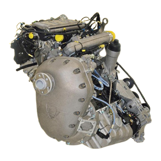
Operation Manual E4.01.02 Dimension and Volume For further information about measurements refer to the Installation Manual of the E4 series (Doc. No.: E4.02.01). Fig. 2.1: Engine view Fig. 2.2: Engine view Issue date: 15.Nov.2016 Revision no: 1 Page: 2-3... -
Page 16: Technical Data Sheet For E4P Engine
Operation Manual E4.01.02 Technical Data Sheet for E4P Engine All speed information’s refer to the revolution speed of the propeller. The revolution speed of the engine is declared separately. For detailed manifold data and dimensions refer to the “Installation Manual” of the E4 engine (Doc. No.: E4.02.01). -
Page 17: High Power Performance
Operation Manual E4.01.02 2.5.2 High power performance Fig. 2.4: Power Curve RPM 2300 Fig. 2.5: Power Curve RPM 2200 Rated Power (100%): 132 kW (177,0 hp) Issue date: 15.Nov.2016 Revision no: 1 Page: 2-5... -
Page 18: Fuel Consumption
100% Power Lever [%] Fig. 2.7: Propeller Setpoint Curve E4P The propeller setpoint is set on the governor by the EECS on the basis of power lever position. This propeller speed (rpm) is held at any airspeed as long as the propeller is within the range of stops. -
Page 19: Engine And Gearbox Data Sheet
Operation Manual E4.01.02 2.5.5 Engine and Gearbox Data Sheet Max. take-off power (max. 5 min.): 132 kW Max. continuous power: 126 kW Max. recommended cruising power: 93,8 kW Max. prop. Over speed: 2500 rpm Max. take-off speed: 2300 rpm Max. continuous speed: 2200 rpm Max. -
Page 20: Limitation Section
6.5 bar (94.25 psi) Approved engine oil types: Brand name SAE Grade AUSTRO ENGINE Aero 5W-40 recommended by Austro Engine GmbH CASTROL Edge Professional A3 5W-40 CASTROL Magnatec Professional A3 5W-40 GULF Formula GX 5W-40 LIQUI MOLY Leichtlauf High Tech... -
Page 21: Coolant
0W-40 Only use above listed engine oils for operation if conformance to MB 229.5 specification is ensured (e.g. by label on the oil packaging). Austro Engine GmbH will not assume any liabilities if other sorts of oil are used. It is not recommended to mix different SAE grades. -
Page 22: Fuel
Any mixture of the different types of additives is not permitted. Both specified brands of additive are qualified for the operation with the certified fuel grades for the E4P engine. To clean the fuel system of the aircraft a higher dosage of the specified additive is allowed under consideration of the instructions of the additive manufacturer. -
Page 23: Speed
Operation Manual E4.01.02 OPERATION WITH ANTI-ICING FUEL ADDITIVES: The application of the following additive is allowed for an operated engine: PRIST Hi-Flash max. 1500 ppm “I-M” (acc. to OST 54-3-175-72-99) max. 3000 ppm Any mixture of the different types of additives is not permitted. PRIST Hi-Flash anti-icing fuel additive is only allowed for operation with Jet A, Jet A-1 (ASTM D 1655) and JP-8 (F34). -
Page 24: Information Section
E4.01.02 2.5.7 Information Section The pressure and temperature in the information section are the optimum of the E4P engine and should be kept in mind. The range between the limits and the optimum can be indicated yellow. For a better overview the optimum can be shown in a green range. -
Page 25: Operating Envelope
Operation Manual E4.01.02 2.5.8 Operating Envelope Fig. 2.8: Banking Rotation Banking rotation deviations from the apparent perpendicular: Around the x - axis: max. ±15 º Around the y - axis max. -35 º / + 25 º Around the z - axis max. -
Page 26: Issue Date: 15.Nov.2016 Revision
Operation Manual E4.01.02 – Intentionally left blank – Issue date: 15.Nov.2016 Revision no: 1 Page: 2-14... -
Page 27: Delivery, Storage And Standstill Period
Close engine openings airproof. The engine must not be started after V-belt tension relieve. Storage over 6 months Contact engine manufacturer Austro Engine GmbH. Engine depreservation Remove all covers from engine openings Install V-belt – refer to Maintenance Manual E4.08.04 ... -
Page 28: Standstill Period
Operation Manual E4.01.02 Standstill Period If the engine is installed already and it is not intended to operate the engine for a longer time, the following is required: Above -30°C: Maximum allowed standstill period: 4 weeks The following procedure has to be performed: Engine Start and Warm Up according to chapter 4.1.2 and chapter 4.1.3. -
Page 29: Operating Instructions
E4.01.02 Operating Instructions These operating instructions are for the using of the E4P engine. For more information about the flight operation the manufacturer of the aircraft has to be contacted. Only authorised persons who hold a valid license are allowed to execute the following steps. -
Page 30: Engine Start
Operation Manual E4.01.02 4.1.2 Engine Start 1. Engine Master – “ON” 2. Glow plug lights – “ON” 3. Glow plugs – „OFF“ (the glow plug lights extinguish after not more than 15 seconds) 4. Propeller Area – Clear and Save 5. -
Page 31: Before Take-Off Check
Operation Manual E4.01.02 4.1.4 Before Take-off Check 1. Engine Instruments – CHECKED 2. Fuel Temperature – CHECKED (refer to chapter 2.5.6.3 and 2.5.7.3 Fuel) 3. Power Levers – “IDLE” 4. ECU-Self Test – PERFORM The ECU cockpit switch (voter switch) must remain in the “Auto”-Position throughout the whole self test procedure. -
Page 32: Restart In Flight
Operation Manual E4.01.02 Restart in flight It is not recommended to shut-off a servicable engine in flight for any reason. The following procedure is recommended to restart an engine in flight: In case of an engine malfunction determine the root cause and only continue in case a safe restart is possible. -
Page 33: Emergency Procedures
Operation Manual E4.01.02 Emergency Procedures Power loss and abnormal engine behaviour ● Power lever “FULL FORWARD” ● Select the fuel tank with sufficient fuel level. ● Continue engine operation ● If abnormal engine behavior is still evident land as soon as possible In case of electrical failures in power generation the internal EECU voter switches automatically to the ECU which provides the better engine performance. -
Page 34: Low Fuel Pressure
Operation Manual E4.01.02 Low fuel pressure Fuel pressure indication is provided. The internal EECU voter switches automatically to the Standby-ECU further the corresponding fuel pump will be switched active. Both fuel pumps can be activated by a switch if the behaviour is not considered as sufficient. High Fuel Temperature ●... -
Page 35: System Description
Operation Manual E4.01.02 System Description Intake System The intake air is cleaned by an air filter and then compressed by the turbo charger. During compression the intake air gets hot. An intercooler between turbo charger and engine is provided to cool the intake air down thus the desired engine performance can be obtained. -
Page 36: Fuel System
E4.01.02 Fuel System In the following picture a typical Fuel System of the E4P engine is shown. Fig. 6.1: Fuel System In the fuel feeding line two feeding pumps are provided which deliver fuel at low pressure to the high pressure pump. -
Page 37: Coolant System
E4.01.02 Coolant System 6.4.1 Standard Coolant System In the following picture the cooling system of the E4P engine is shown. Small Circuit Fig. 6.2: Cooling system The water pump pumps the coolant through the engine. The coolant leaves the engine at the heat exchanger connection point and at the thermostat. -
Page 38: Coolant System With Optional Gearbox Oil Cooler
Operation Manual E4.01.02 6.4.2 Coolant System with optional Gearbox Oil Cooler In addition to the standard cooling circuit a Gearbox Oil-Water Heat Exchanger (HEX) is integrated in the circuit (see Fig. 6.3). The example for an acceptable standard cooling circuit (refer to Fig. 6.2) is only extended by the gearbox HEX. -
Page 39: Lubricating System
Operation Manual E4.01.02 Lubricating System The lubricating system of the engine consists of an internal oil pump, which pumps the engine oil through the oil filter, the coolant-oil heat exchanger and the lubrication ports of the engine. In front of the oil filter the oil pressure is measured. The oil temperature is measured in oil sump next to the oil filler neck. -
Page 40: Electrical System
– Sensors & Actuators – The EECS Block Diagram shows the connection between the EECS components which are used in the E4P Engine and displays also the Interface from the Airframe to the EECS of the E4P. Engine Sensors Actuators... - Page 41 Operation Manual E4.01.02 The starter is manually controlled by the pilot. The EECU will detect a running engine at 600rpm (Propeller) and further activation is not necessary. The Generator is a 28V/70A power supply which consists of an alternator mounted to the engine and an external regulator.
-
Page 42: Eecu Functions
Operation Manual E4.01.02 6.6.1 EECU Functions Sensors and Actuators Sensors ECU A Camshaft Sensor EECU Crankshaft Sensor Intake Air Temperature Sensor Boost Pressure Sensor Power Lever Sensor Actuators ECU A Shared Sensors Injectors (4) Gearbox Temperature Sensor Boost Pressure Acutator Oil Temperature Sensor Rail Pressure Relay... - Page 43 Operation Manual E4.01.02 Sensors ● Power Lever Sensor Power Lever Sensor position evaluation Hall Effect Sensor with dual output ● Crank Shaft Sensor Engine speed evaluation ● Cam Shaft Sensor Engine position evaluation ● Fuel Pressure Sensor Used for evaluation of the fuel pressure after the pre-supply pump ●...
- Page 44 Operation Manual E4.01.02 EECU Power Supply ECU A ECU A Sensors ECU A Relay Shared Sensors Voter Actuators Matrix Sensors ECU B ECU B Power Supply ECU B 3way Cockpit Engine Switch Power Indications / Sensor A Sensor B Lever Annunciations ECU A ECU B...
- Page 45 Operation Manual E4.01.02 ● Failure monitoring / Fault Code Memory Reported Failures are stored in the Fault Code Memory Up to 20 entries Can lead to an ECU switch over Can activate the ECU caution Can cause a substitute function (e.g. substitute value) ...
-
Page 46: Engine Speed And Power Regulation
Operation Manual E4.01.02 6.6.2 Engine Speed and Power Regulation The desired propeller speed set point is calculated depending on the power lever sensor position. The current engine speed is used to compute the deviation of the actual propeller speed from the set point. The deviation is converted into an output ratio for the set point actuator. - Page 47 Operation Manual E4.01.02 Fig. 6.7: EECU and Governor Issue date: 15.Nov.2016 Revision no: 1 Page: 6-13...
-
Page 48: Error Handling
Not indicated errors In case of a latched caution an unscheduled maintenance is necessary and Austro Engine GmbH has to be informed. 6.6.3.1 Description of ECU Switch Over In case of an ECU switch over, the other ECU channel takes over the control of the engine. -
Page 49: Resetting Ecu Caution In Operation
Operation Manual E4.01.02 6.6.3.2 Resetting ECU caution in Operation A procedure may be performed for resetting a non-latched caution according to the description in this section. If a non-latched caution failure occurs, this may lead to an ECU switch over e.g from ECUA to ECU B. In the then passive ECU the last valid caution status is stored and not reset, even if the cause of the caution is not valid any more. -
Page 50: Caution Handling Table Software Vc33_0_05_18_Pre1
Operation Manual E4.01.02 6.6.3.3 Caution Handling Table Software VC33_0_05_18_pre1 The table in this section applies to SW versions VC33_0_05_18_pre1 and later versions. Latched Caution Indication Failure Caution Caution ECU Switch Failure description Code Indication Latched Over Analogue-digital converter failure 2319 YES Power lever sensor 1 failure 1222 YES Power lever sensor 2 failure... - Page 51 Operation Manual E4.01.02 Failure Caution Caution ECU Switch Failure description Code Indication Latched Over Main relay path 1 failure 1A01 YES Main relay path 2 failure 1A02 YES Main relay path 3 failure 1A03 YES Engine oil pressure sensor failure 1B13 YES Oil temperature sensor 2014 YES...
- Page 52 Operation Manual E4.01.02 Failure Caution Caution ECU Switch Failure description Code Indication Latched Over Coolant temperature sensing of ECU A and B not consistent 1B07 YES Fuel pressure sensing of ECU A and B not consistent 1B08 YES Fuel temperature sensing of ECU A and B not consistent 1B09 YES Gearbox oil temperature sensing of ECU A...
- Page 53 Operation Manual E4.01.02 Failure Caution Caution Switch Failure description Code Indication Latched Over Common rail, pressure control valve failure 1 2019 YES Common rail, pressure control valve failure 2 2020 YES Common rail, pressure control valve failure 3 2021 YES Common rail, pressure control valve failure 4 2023 YES Common rail, pressure control valve failure 5...
- Page 54 Operation Manual E4.01.02 – Intentionally left blank – Issue date: 15.Nov.2016 Revision no: 1 Page: 6-20...
-
Page 55: Additional Information
(mechanical) propeller control lever. With the single power lever installation of the E4P engine, the self test button must be pressed during the automatic run up. The self test button in the cockpit has to be released once before a new (subsequent) self test can be initiated by pressing the button again. - Page 56 These technical data and the information contain therein are the property of Austro Engine GmbH and may not be reproduced either in full or in part or passed on to a third party without written consent from Austro Engine GmbH.
Need help?
Do you have a question about the E4P and is the answer not in the manual?
Questions and answers