Sign In
Upload
Manuals
Brands
Aplisens Manuals
Transmitter
LI-24L
Aplisens LI-24L Manuals
Manuals and User Guides for Aplisens LI-24L. We have
4
Aplisens LI-24L manuals available for free PDF download: User Manual, Manual
Aplisens LI-24L User Manual (27 pages)
TEMPERATURE TRANSMITTERS
Brand:
Aplisens
| Category:
Transmitter
| Size: 2 MB
Table of Contents
Table of Contents
4
Introduction
6
Purpose of the Document
6
Registered Trademarks
6
Definitions and Abbreviations
7
Table 1. Definitions and Abbreviations
7
Transmitter Set Range
8
Figure 1. Set Range and Measurement Limits
8
Safety
9
Figure 2. Warning Plate - Protective Seal
9
Transport and Storage
10
Delivery Check
10
Transport
10
Storage
10
Guarantee
10
Identification
11
Manufacturer's Address
11
Transmitter Identification
11
CE Mark, Declaration of Conformity
11
Figure 3. Examples of LI-24G Transmitter Nameplates in Standard and Exi Version
11
Figure 4. Examples of LI-24L Transmitter Nameplates in Standard and Exi Version
11
Installation
12
General Recommendations
12
Installation of Rail-Mounted Transmitter LI-24L on a DIN Rail
12
Figure 5. LI-24L Transmitter Installation on a DIN Rail
12
Installation of Head-Mounted Transmitter LI-24G in the Housing
13
Figure 6. Installation of the LI-24G Transmitter in an Example Enclosure Manufactured by Aplisens
13
Figure 7. Fastening Screw Lock Protection in the LI-24G Transmitter
14
Electrical Connection
15
Cable Connection to Transmitter Terminals
15
Cable Connection
15
Figure 8. Markings of LI-24L Transmitter Terminals
15
Figure 9. Markings of LI-24G Transmitter Terminals
15
Options for Connecting Sensors, Potentiometers and Voltage Sources to the Transmitter
16
Figure 10. Methods of Connecting Sensors, Potentiometers and Voltage Sources
16
Connection of Transmitters with the Option of Using Local HART Communication
17
Figure 11. Electrical Connection 4
17
Figure 12. Electrical Connection 4
17
Transmitter Power Supply
18
Transmitter Supply Voltage
18
Specifications of Electrical Switching Terminals
18
Resistance Load in Power Supply Line
18
Table 2. Permissible Transmitter Supply Voltages
18
Shielding, Equipotential Bonding
19
Final Inspection of Cabling
19
Start-Up
19
Alarm Configuration
19
Figure 13. Set Range Current, Saturation Currents, Alarm Currents in Standard Mode
19
Figure 14. Set Range Current, Saturation Currents, Alarm Currents in NAMUR Mode
20
Figure 15. LED Indicator on the LI-24L Transmitter
21
Configuration of the Operating Mode
22
Metrological Parameters, Types of Sensors, Measuring Ranges and Errors
22
Table 3. Metrological Parameters of RTD Sensors
23
Table 4. Metrological Parameters of Thermocouples
24
Table 5. Types of Measurements, Linearization and Mathematical Operations
25
Operation
26
Operating Temperature
26
Remote Configuration of Setpoints (HART 5)
26
Compatible Devices
26
Compatible Configuration Software
26
Method of Connecting Communication Devices
26
Maintenance
27
Periodic Inspections
27
Non-Periodic Inspections
27
Spare Parts
27
Repair
27
Returns
27
Scrapping, Disposal
27
History of Revisions
27
Advertisement
Aplisens LI-24L User Manual (28 pages)
TEMPERATURE TRANSMITTERS
Brand:
Aplisens
| Category:
Transmitter
| Size: 2 MB
Table of Contents
Table of Contents
4
1 Introduction
6
Purpose of the Document
6
Registered Trademarks
6
Definitions and Abbreviations
7
Table 1. Definitions and Abbreviations
7
Transmitter Set Range
8
Figure 1. Set Range and Measurement Limits
8
Figure 2. Warning Plate - Protective Seal
9
2 Safety
9
3 Transport and Storage
10
Delivery Check
10
Transport
10
Storage
10
4 Guarantee
10
Figure 3. Examples of LI-24G Transmitter Nameplates in Standard and Exi Version
11
Figure 4. Examples of LI-24L Transmitter Nameplates in Standard and Exi Version
11
5 Identification
11
CE Mark, Declaration of Conformity
11
Manufacturer's Address
11
Transmitter Identification
11
Figure 5. LI-24L Transmitter Installation on a DIN Rail
12
Installation of Head-Mounted Transmitter LI-24G in the Housing
13
6 Installation
12
General Recommendations
12
Installation of Rail-Mounted Transmitter LI-24L on a DIN Rail
12
Figure 6. Installation of the LI-24G Transmitter in an Example Enclosure Manufactured by Aplisens
13
Figure 7. Fastening Screw Lock Protection in the LI-24G Transmitter
14
Figure 8. Markings of LI-24L Transmitter Terminals
15
Figure 9. Markings of LI-24G Transmitter Terminals
15
7 Electrical Connection
15
Cable Connection to Transmitter Terminals
15
Cable Connection
15
Figure 10. Methods of Connecting Sensors, Potentiometers and Voltage Sources
16
Options for Connecting Sensors, Potentiometers and Voltage Sources to the Transmitter
16
Connection of Transmitters with the Option of Using Local HART Communication
17
Figure 12. Electrical Connection 4
17
Table 2. Permissible Transmitter Supply Voltages
18
Final Inspection of Cabling
19
Shielding, Equipotential Bonding
19
Figure 11. Electrical Connection 4
17
Transmitter Power Supply
18
Transmitter Supply Voltage
18
Specifications of Electrical Switching Terminals
18
Resistance Load in Power Supply Line
18
8 Operation
20
Operating Temperature
20
Remote Configuration of Setpoints (HART 5)
20
Compatible Devices
20
Compatible Configuration Software
20
Method of Connecting Communication Devices
20
Figure 13. Set Range Current, Saturation Currents, Alarm Currents in Standard Mode
21
9 Start-Up
21
Alarm Configuration
21
Figure 14. Set Range Current, Saturation Currents, Alarm Currents in NAMUR Mode
22
Configuration of the Operating Mode
23
Figure 15. LED Indicator on the LI-24L Transmitter
23
Table 3. Types of Measurements, Linearization and Mathematical Operations
25
10 Maintenance
26
Periodic Inspections
26
Non-Periodic Inspections
26
Spare Parts
26
Repair
26
Returns
26
11 Scrapping, Disposal
27
12 History of Revisions
27
Aplisens LI-24L User Manual (28 pages)
Temperature transmitters
Brand:
Aplisens
| Category:
Transmitter
| Size: 2 MB
Table of Contents
Table of Contents
4
Introduction
6
Purpose of the Document
6
Registered Trademarks
6
Definitions and Abbreviations
6
Table 1. Definitions and Abbreviations
6
Transmitter Set Range
7
Figure 1. Set Range and Measurement Limits
7
Safety
8
Figure 2. Warning Plate - Protective Seal
8
Transport and Storage
9
Delivery Check
9
Transport
9
Storage
9
Guarantee
9
Identification
10
Manufacturer's Address
10
Transmitter Identification
10
CE Mark, Declaration of Conformity
10
Figure 3. Examples of LI-24G Safety Transmitter Nameplates in Standard and Exi Version
10
Figure 4. Examples of LI-24L Safety Transmitter Nameplates in Standard and Exi Version
10
Installation
11
General Recommendations
11
Installation of Rail-Mounted Transmitter LI-24L Safety on a DIN Rail
11
Figure 5. LI-24L Safety Transmitter Installation on a DIN Rail
11
Installation of Head-Mounted Transmitter LI-24G Safety in the Housing
12
Figure 6. Installation of the LI-24G Safety Transmitter in an Example Enclosure Manufactured by Aplisens
12
Figure 7. Fastening Screw Lock Protection in the LI-24G Safety Transmitter
13
Electrical Connection
14
Cable Connection to Transmitter Terminals
14
Figure 8. Markings of LI-24L Safety Transmitter Terminals
14
Figure 9. Markings of LI-24G Safety Transmitter Terminals
14
Options for Connecting Sensors, Potentiometers and Voltage Sources to the Transmitter15
15
Figure 10. Methods of Connecting Sensors, Potentiometers and Voltage Sources
15
Connection of Transmitters with the Option of Using Local HART Communication
16
Figure 11. Electrical Connection 4
16
Figure 12. Electrical Connection 4
16
Transmitter Power Supply
17
Transmitter Supply Voltage
17
Specifications of Electrical Switching Terminals
17
Resistance Load in Power Supply Line
17
Shielding, Equipotential Bonding
17
Final Inspection of Cabling
17
Table 2. Permissible Transmitter Supply Voltages
17
Start-Up
18
Alarm Configuration
18
Figure 13. Set Range Current, Saturation Currents, Alarm Currents
18
Figure 14. LED Indicator on the LI-24L Safety Transmitter
19
Configuration of the Operating Mode
20
Metrological Parameters, Types of Sensors, Measuring Ranges and Errors
21
Table 3. Metrological Parameters of RTD Sensors
21
Table 4. Metrological Parameters of Thermocouples
22
Table 5. Types of Measurements, Linearization and Mathematical Operations
23
Operation
24
Operating Temperature
24
Remote Configuration of Setpoints (HART)
24
Compatible Devices
24
Compatible Configuration Software
24
Method of Connecting Communication Devices
24
Maintenance
25
Periodic Inspections
25
Non-Periodic Inspections
25
Spare Parts
25
Repair
25
Returns
25
Scrapping, Disposal
26
History of Revisions
26
Advertisement
Aplisens LI-24L Manual (16 pages)
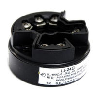
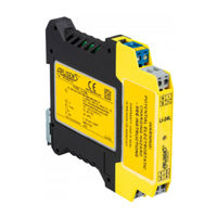
RAIL / HEAD-MOUNTED SMART TEMPERATURE TRANSMITTERS
Brand:
Aplisens
| Category:
Transmitter
| Size: 2 MB
Table of Contents
Table of Contents
3
1 Introduction
5
2 Complete Delivery Checklist
5
3 Identification Marks
6
4 Construction of the Transmitter
7
5 Electrostatic Hazards
7
6 Special Conditions of Use
8
7 INTRINSICALLY-SAFE Exi TRANSMITTERS LI24G and LI-24G SAFETY
8
Standards Used for Assessment
8
Transmitter Intrinsic Safety Designations
8
Permissible Input and Output Parameters of the Intrinsic Safety Transmitters LI-24G and LI-24G Safety
9
8 INTRINSICALLY-SAFE Exi TRANSMITTERS LI24L and LI-24L SAFETY
9
Standards Used for Assessment
9
Table 2. Permissible Output Parameters in the Temperature Sensor Circuit (Terminals "1", "2", "3", "4", "5") for the LI-24G and LI-24G Safety Transmitters in Exi Version
9
Table 1. Permissible Input Parameters in the Power Supply Circuit (Terminals "+", "-") for LI-24G and LI-24G Safety Transmitters in Exi Version
9
Table 3. Permissible Input Parameters in the Power Supply Circuit (Terminals "+", "-") for LI-24L and LI-24L Safety Transmitters in Exi Version
10
Linear Power Supply Example
11
Rectangular Power Supply Example
11
Trapezoidal Power Supply Example
11
Transmitter Intrinsic Safety Designations
9
Load Resistance
10
Minimum and Maximum Supply Voltage
10
Permissible Input and Output Parameters of the Intrinsic Safety Transmitters LI-24L and LI-24L Safety
10
11 CONNECTING Exi TRANSMITTERS
12
12 Additional Information
13
History of Revisions
13
Advertisement
Related Products
Aplisens LI-24
Aplisens LI-24G
Aplisens LI-24L Exi
Aplisens LI-24G Exi
Aplisens LI-24ALW Safety
Aplisens LI-24/Ex
Aplisens 0005 0004 0006 0000 0000 0002 0001 72
Aplisens 0005 0007 0005 0000 0000 0000 0001 05
Aplisens 0005 0007 0005 0000 0000 0001 0001 53
Aplisens 0005 0007 0005 0000 0000 0003 0001 52
Aplisens Categories
Transmitter
Measuring Instruments
Accessories
Media Converter
Monitor
More Aplisens Manuals
Login
Sign In
OR
Sign in with Facebook
Sign in with Google
Upload manual
Upload from disk
Upload from URL