Aplisens LI-24ALW Safety Manuals
Manuals and User Guides for Aplisens LI-24ALW Safety. We have 3 Aplisens LI-24ALW Safety manuals available for free PDF download: User Manual
Aplisens LI-24ALW Safety User Manual (25 pages)
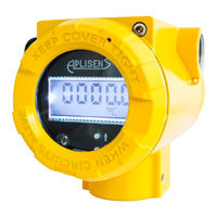
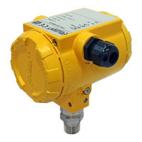
SMART TEMPERATURE TRANSMITTER
Brand: Aplisens
|
Category: Transmitter
|
Size: 1 MB
Table of Contents
Advertisement

Aplisens LI-24ALW Safety User Manual (25 pages)
SMART TEMPERATURE TRANSMITTER
Brand: Aplisens
|
Category: Transmitter
|
Size: 1 MB
Table of Contents
Aplisens LI-24ALW Safety User Manual (24 pages)
TEMPERATURE TRANSMITTER
Brand: Aplisens
|
Category: Transmitter
|
Size: 1 MB
Table of Contents
Advertisement