Sign In
Upload
Manuals
Brands
Anritsu Manuals
Measuring Instruments
VNA master
Anritsu VNA master Manuals
Manuals and User Guides for Anritsu VNA master. We have
2
Anritsu VNA master manuals available for free PDF download: Manual, User Manual
Anritsu VNA master Manual (296 pages)
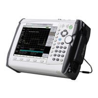
Spectrum Analyzer for Anritsu RF and Microwave Handheld Instruments
Brand:
Anritsu
| Category:
Measuring Instruments
| Size: 22 MB
Table of Contents
Table of Contents
3
Chapter 1-General Information
11
Introduction
11
Selecting a Measurement Mode
11
Contacting Anritsu
12
Chapter 2-Spectrum Analyzer
13
Introduction
13
General Measurement Setups
13
Making Spectrum Analyzer Measurements
13
Setting Frequency
13
Setting Bandwidth Parameters
14
Setting Sweep Parameters
15
Spectrum Analyzer MG PN: 10580-00349 Rev. M
19
Resolution Bandwidth
20
Video Bandwidth
20
Sweep Limitations
21
Attenuator Functions
21
Detection
22
Indications of Excessive Signal Level
22
Preamplifier Measurement Example
26
Field Measurements
26
Field Strength
27
Antenna Calculations
28
Occupied Bandwidth Measurement
29
Channel Power Measurement
31
Channel Power Measurement for GSM
31
Adjacent Channel Power Measurement
33
EMF Measurement (Option 444)
34
Out-Of-Band Spurious Emission Measurements
35
In-Band/Out-Of-Channel Measurements
37
AM/FM/SSB Demodulation
38
Carrier to Interference Ratio Measurement
39
Emission Mask (In-Band)
42
Spurious Emissions (Out-Of-Band)
43
Creating a New Spurious Emission Mask
43
Loading an Existing Mask
45
Modifying an Existing Mask
45
Spurious Emissions (Out-Of-Band) Measurements
47
Coverage Mapping (Option 431)
49
IQ Waveform Capture (Option 24)
50
Waveform Capture Setup
50
Capturing a Waveform
51
Spectrum Analyzer Menus
52
Marker Menu
53
Measure Menu (1 of 5)
54
Measure Menu (2 of 5)
55
Measure Menu (3 of 5)
56
Measure Menu (4 of 5)
57
Measure Menu (5 of 5)
58
Sweep Menu
59
Trace Menus
60
Limit Menus
60
Application Options Menu
61
Freq (Frequency) Menu
62
Freq (Frequency) Menu (Continued)
63
Frequency Menu (Freq 1/2) with Offset Function
64
Freq 2/2 Menu
66
Amplitude Menu
68
Units & Detection Menu
69
Span Menu
70
Zero Span if BW Menu (Option 89)
71
BW (Bandwidth) Menu
72
Marker Menu
73
More Peak Options (Marker & Peak) Menu
74
Marker 2/2 Menu
75
Sweep Menu
76
Sweep Mode Menu
77
Triggering Menu
78
Trigger Source Menu
79
Gate Setup Menu
80
Measure Menu
81
Power and BW Menu
82
Field Strength Menu
83
OCC BW Menu
84
Channel Power Menu
85
ACPR Menu
86
EMF Menu (Option 444)
88
Masks and C/I Menu
89
Emission Mask (In-Band) Menu
90
Spurious Emissions (Out-Of-Band) Menu
91
C/I Menu
93
C/I Signal Type Menu
94
AM/FM Demod 1/2 Menu
95
Demod Type (AM/FM) Menu
96
AM/FM Demod 2/2 (More) Menu
97
Generator Menu (Optional)
98
IQ Waveform Capture Menu (Option 24)
99
IQ Capture Triggering Menu
100
IQ Capture Save Menu
100
IQ Capture Frequency/Amplitude Menu
101
Coverage Mapping Menu (Option 431)
101
Trace Menu
102
Trace a Ops Menu
104
Trace B Ops Menu
105
Trace C Ops Menu
106
Limit Menu
107
Edit Menu (Limit)
108
Edit Menu (Continued)
109
Limit Move Menu
110
Limit Envelope Menu
111
Limit Advanced Menu
113
Application Options Menu
114
Other Menus
114
Chapter 3-Interference Analyzer (Option 25)
115
Introduction
115
General Measurement Setups
115
Spectrum
115
Spectrogram
116
Section 3-4 "Spectrogram
116
Signal Strength
118
Section 3-5 "Signal Strength
118
Received Signal Strength Indicator (RSSI)
119
Section 3-6 "Received Signal Strength Indicator (RSSI)
119
Signal ID
120
Section 3-7 "Signal ID
120
Interference Mapping
122
Section 3-8 "Interference Mapping
122
Note
122
Overview
123
Interference Mapping (Antenna Only)
124
Interference Mapping (MA2700A and Antenna)
128
Save the Mapping Information
133
Interference Analyzer (IA) Menu Maps
136
Measurements Menu (1 of 4)
137
Measurements Menu (2 of 4)
138
Measurements Menu (3 of 4)
139
Measurements Menu (4 of 4)
140
Marker Menus
141
Sweep Menus
142
Trace Menus
143
Limit Menus
143
Application Options Menu
144
Freq (Frequency) Menu
145
Freq (Frequency) Menu (Continued)
146
Frequency Menu with Offset Function
147
Freq 2/2 Menu
148
Span Menu
150
Zero Span if BW Menu (Option 89)
151
Amplitude Menu
152
Units & Detection Menu
153
BW (Bandwidth) Menu
154
Measurements Menu
156
[Spectrum] Measure Menu
156
Power and BW Menu
157
Field Strength Menu
158
OCC BW Menu
159
Channel Power Menu
160
ACPR Menu
161
EMF Menu (Option 444)
163
Masks and C/I Menu
164
Emission Mask (In-Band) Menu
165
C/I Menu
166
C/I Signal Type Menu
167
AM/FM Demod 1/2 Menu
168
Demod Type Menu
169
AM/FM Demod 2/2 Menu
170
Generator Menu (Optional)
171
IQ Waveform Capture Menu (Option 24)
172
IQ Capture Triggering Menu
173
IQ Capture Save Menu
173
IQ Capture Frequency/Amplitude Menu
174
Coverage Mapping Menu (Option 431)
175
Spectrogram Menu
176
Signal Strength Menu
177
RSSI Menu
178
Signal ID Menu
179
Interference Mapping Menu
180
Bearing Lines Menu
181
Mapping Save/Recall Menu
182
Direction Finding Menu
183
Pan & Zoom Menu
184
DF Sound Settings Menu
184
Marker Menu
185
Marker and Peak Menu
186
Marker 2/2 Menu
187
Sweep Menu
188
Sweep Mode Menu
189
Triggering Menu
190
Trigger Source Menu
191
Gate Setup Menu
192
Trace Menu
193
Trace a Ops Menu
194
Trace B Ops Menu
195
Trace C Ops Menu
196
Limit Menu
197
[Limit] Edit Menu
198
[Limit] Edit Menu (Continued)
199
Limit Move Menu
200
Limit Envelope Menu
201
Limit Advanced Menu
203
Application Options
204
Other Menus
204
Chapter 4-Channel Scanner (Option 27)
205
Introduction
205
General Measurement Setups
205
Sample Procedure
206
Custom Setup Measurements
207
Custom Setup Example
207
Script Master Measurement Setup
208
Channel Scanner Menu Map
210
Scanner Menu
211
Channel Scan Menu
211
Freq Scan Menu
212
Scan Script Master Menu
213
Amplitude Menu
214
Custom Scan Menu
215
Measurements Menu
216
Sweep Menu
218
Measure Menu
218
Trace Menu
218
Limit Menu
218
Other Menus
218
Chapter 5-CW Signal Generator (Option 28)
219
Introduction
219
Required Equipment
219
Procedure
220
Chapter 6-Coverage Mapping (Option 431)
223
Introduction
223
General Measurement Setups
223
Spectrum Analysis Settings
223
Coverage Mapping
224
Anritsu Easymap Tools
226
Instrument Settings
227
Map the Signal Strength
229
Save the Coverage Mapping Information
231
Coverage Mapping Menus
235
Coverage Mapping Menu
237
Mapping Save/Recall Menu
238
Pan & Zoom Menu
239
Measurement Setup Menu
241
Point Distance/Time Setup Menu
242
RSSI Menu
243
ACPR Menu
244
Field Strength Menu
245
Chapter 7-AM/FM/PM Analyzer (Option 509)
247
Introduction
247
General Measurement Setup
248
Example FM Demodulation Measurement
250
AM/FM/PM Analyzer Menus
254
Map of Main Menus
254
Map of Frequency Menus
255
Map of Measurements Menus
256
Map of Audio Demod Menus
257
RF Freq (Frequency) Menu
258
RF Span Menu
259
Signal) Standard List Menu
260
Amplitude Menu
261
Setup Menu
262
Measurements Menu
263
RF Spectrum Menu
264
Audio Spectrum am Menu
265
Audio Waveform am Menu
266
Audio Spectrum FM Menu
267
Audio Waveform FM Menu
268
Audio Spectrum PM Menu
269
Audio Waveform PM Menu
270
Coverage Mapping Menu
271
Mapping Save/Recall Menu
272
Measurement Setup Menu
273
Point Distance/Time Setup Menu
274
Audio Demod am Menu
275
Audio Demod FM Menu
276
Marker Menu
277
Chapter 8-Bias Tee (Option 10)
279
Introduction
279
Bias Tee Menu
281
Chapter 9-EMF (Option 444)
283
Introduction
283
Connecting the Antenna
283
EMF Menu
284
EMF Auto Menu
285
Trace Menu
286
Measurement Results
287
Pass/Fail
288
Advertisement
Anritsu VNA master User Manual (164 pages)
vector network analyzer with spectrum analyzer
Brand:
Anritsu
| Category:
Measuring Instruments
| Size: 6 MB
Table of Contents
Safety Symbols
7
Table of Contents
9
Chapter 1-General Information
17
Introduction
17
Contacting Anritsu
17
Anritsu Service Centers
18
Additional Documents
18
VNA Master Specifications
18
Identifying the Connections
19
Description
20
Soft Carrying Case and Tilt Bail
21
VNA Master Soft Carrying Case
21
VNA Master Tilt Bail Stand
23
Preventive Maintenance
24
1-10 Calibration Requirements - Vector Network Analyzer
24
Annual Verification
24
1-12 Battery Replacement
25
1-13 ESD Cautions
26
Chapter 2-Quick Start Guide
27
Introduction
27
Turning the VNA Master on for the First Time
27
Front Panel Overview
29
Front Panel Overview Image
30
Battery Charge LED (Green)
31
Power LED (Green)
31
Fan Inlet and Exhaust Ports
31
Typical Vector Network Analyzer Display
32
Instrument Settings Summary
35
Typical Spectrum Analyzer Display
37
Front Panel Keys
38
Esc Key
38
Enter Key
38
Arrow Keys
38
Shift Key
38
Back Key
38
Plus/Minus (+/-) Key
38
Number Keypad
39
Rotary Knob
39
Function Hard Keys
39
Soft Keys
39
Soft Key Types
39
Select
39
Input
40
Toggle
40
Switching
40
Parameter Setting
41
Text Entry
41
2-10 Mode Selector
45
Test Panel Connectors
46
Ms202Xc Test Panel Connectors
46
Ms203Xc Test Panel Connectors
47
LAN Connection
48
USB Interface - USB Type Mini-B
50
USB Interface - USB Type a
50
2-12 VNA Master Connectors
51
External Power
51
Ext Trigger (50 Ohm)
51
Ext Freq Ref (50 Ohm)
51
RF Detector (DIN)
51
Port 1 (50 Ohm)
52
Port 2 (50 Ohm)
52
Bias Input Port 1
52
Bias Input Port 2
52
Bias Status LED
52
Headset Jack
53
2-13 Connector Care
54
Connecting Procedure (for Type-N and Type-K)
54
Disconnecting Procedure
54
GPS Antenna Connector
55
Reference Output, 10 Mhz (50 Ohm)
55
Spectrum Analyzer RF in (50 Ohm)
55
2-14 Symbols and Indicators
56
Battery Symbol
56
Hold
57
Single Sweep
57
2-15 Memory Profile and Security Issues
58
2-16 System Settings
59
Power on Self Test
59
Vector Network Analyzer Mode
59
Spectrum Analyzer Mode
59
Frequency Blanking
59
2-17 File Types
60
File Management
60
Chapter 3 - Power Monitor, Option 5
61
Introduction
61
Using the Power Monitor
61
Zeroing the Power Monitor
61
Measuring High Input Power Levels
61
Displaying Power in Dbm or in Watts
62
Setting Relative Power
62
Power Monitor Display
63
Power Monitor Menu
63
Chapter 4 - Secure Data Option 7
65
Introduction
65
Procedure
65
Calibration Setup
66
Memory Profile and Security Issues
67
Frequency Blanking
69
Chapter 5-File Management
71
Introduction
71
File Types
71
Managing Files
72
Save Files
72
Save Dialog Box
73
Recall Files
74
Recall Dialog Box
74
Copy Files
75
Delete Files
76
Delete Dialog Box
76
File Menu Overview
77
File Menu
78
Save Menu
79
Save Location Menu
80
File Type Menu
81
Save on
82
Recall Menu
83
Copy Menu
84
Delete Menu
85
Chapter 6-System Operations
87
Introduction
87
System Menu Group Overview
88
Additional Menu Group
89
System Menu
90
System Options Menu
91
System Options 2/2 Menu
92
Application Options Menu (VNA Mode)
93
Time Domain Options Menu (VNA Mode)
94
Application Options Menu (SPA Mode)
95
Meas Gain Range Menu (VNA Mode)
95
Display Settings Menu
96
6-10 Reset Menu
97
Preset Menu
98
6-12 Power on Self Test
99
6-13 Updating the VNA Master Firmware
100
Chapter 7 - GPS Receiver, Option 31
101
Introduction
101
Activating the GPS Feature
101
GPS Menu
103
GPS Info Window
104
Tracked Satellites
104
Latitude and Longitude
104
Altitude
104
Utc
104
Fix Available
105
Almanac Complete
105
Antenna Status
105
Receiver Status
105
Other Status Messages
106
GPS Antenna Voltage
106
GPS Antenna Current
106
Saving and Recalling Traces with GPS Information
106
Saving Traces with GPS Information
106
Recalling GPS Information
106
Chapter 8-Anritsu PC Software Tools
107
Introduction
107
Anritsu Tool Box
107
Line Sweep Tools
108
Master Software Tools
109
Easymap Tools
110
Appendix A-Supplemental Documentation
111
Introduction
111
A-1 Introduction
111
Appendix B-Signal Standards B-1 Introduction
113
Appendix C-Error Messages
117
Introduction
117
Reset Options
117
Reset Via Instrument Menus
117
Reset from off Condition
117
C-1 Introduction
117
Self Test or Application Self Test Error Messages
118
Self Test
118
Application Self Test Results Window - VNA
120
Application Self Test (Vector Network Analyzer Mode Only
120
Application Self Test Results Window - SPA
121
Operation Error Messages
122
Fan Failure
122
High Temp Warning
122
Operation Not Permitted in Recall Mode
122
PMON PLD Fail
123
Power Supply
123
Error Saving File. General Error Saving File
123
Vector Network Analyzer Specific Warning Messages
124
Bias Tee Cannot be Enabled for Start Freq < 2Mhz
124
Bias Tee Is Not Allowed for Start Freq < 2Mhz
124
Changing Source Power
124
No Valid Calibration to Change Correction
124
Cannot Continue with Calculating
124
Bias Tee State Cannot be Changed During Calibration
124
Turning Bias Tee to off
125
Calibration will be Lost after Change
125
Changes Not Allowed During Calibration
125
Option 10 (Bias Tee) Not Enabled
125
No External Reference Signal Detected
125
Limit Is Not Available for this Graph Type
125
Appendix D-Tower Mounted Amplifiers
127
Introduction
127
D-1 Introduction
127
Appendix E-Coaxial Cable Technical Data
129
Coaxial Cable Technical Data
129
Appendix F-Waveguide Data
133
Introduction
133
Calibration Components
133
F-1 Introduction
133
F-3 Waveguide-To-Coaxial Adapters
134
F-4 Flange Compatibility
135
Flange Compatibility
137
Universal Flange Compatibility
138
F-5 Waveguide Technical Data
139
Waveguide Technical Data
142
Appendix G-More about DHCP
143
Introduction
143
G-1 Introduction
143
G-2 Ethernet Configuration
144
Ethernet Config
145
Ethernet Menu
146
Using DHCP
146
Static IP Address
146
IP Address
147
Default Gateway
147
Subnet Mask
147
Example 1
147
Example 2
147
G-5 Operating System Tools
147
Ipconfig Tool
148
Appendix H-Glossary of Terms
151
Glossary Terms
152
Index
157
Advertisement
Related Products
Anritsu VectorStar
Anritsu 3656C W1
Anritsu 37 C Series
Anritsu 37 D Series
Anritsu 37225C
Anritsu 37247C
Anritsu 37247D
Anritsu 37269C
Anritsu 37269D
Anritsu 37277C
Anritsu Categories
Measuring Instruments
Test Equipment
Portable Generator
Control Unit
Thermometer
More Anritsu Manuals
Login
Sign In
OR
Sign in with Facebook
Sign in with Google
Upload manual
Upload from disk
Upload from URL