Sign In
Upload
Manuals
Brands
Anritsu Manuals
Signal Processors
Rubidium MG362 1A Series
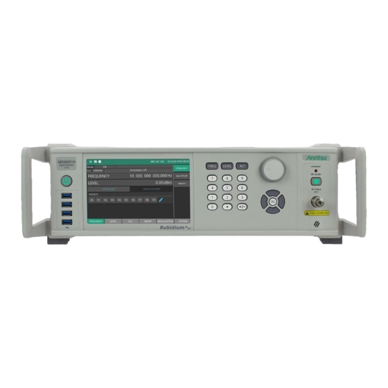
Anritsu Rubidium MG362 1A Series Manuals
Manuals and User Guides for Anritsu Rubidium MG362 1A Series. We have
4
Anritsu Rubidium MG362 1A Series manuals available for free PDF download: Maintenance Manual, Operation Manual
Anritsu Rubidium MG362 1A Series Maintenance Manual (294 pages)
Brand:
Anritsu
| Category:
Portable Generator
| Size: 12 MB
Table of Contents
Table of Contents
3
Chapter 1 - General Information
13
Scope of Manual
13
Document Format
13
Introduction
13
Description
13
Identification Number
13
Additional Documentation
14
Contacting Anritsu
14
Options
14
Level of Maintenance
14
Preventive Maintenance
14
Troubleshooting
15
Repair
15
Calibration
15
ESD Requirements
15
Chapter 2 - Functional Description
17
Introduction
17
Major Subsystems
17
Digital Control
17
Front Panel Assembly
17
Frequency Synthesis
17
YIG Assembly
17
Alc
18
RF Deck
18
Power Supply
18
Inputs/Outputs
18
Motherboard/Interconnections
18
Frequency Synthesis
21
Khz to 2.2 Ghz Digital down Converter
21
To 43.5 Ghz (Model MG36241A)
21
Frequency Extension Module (FEM)
22
Frequency Switching Speed
22
Step Sweep Mode
22
Modulation
23
Amplitude Modulation
23
Pulse Modulation Operation
23
Pulse Generator Operation
23
Frequency Modulation
23
Phase Modulation
24
ALC Loop Operation
25
External Leveling
25
ALC Slope
25
Power Sweep
25
RF Deck Assemblies
26
RF Deck Configurations
26
YIG-Tuned Oscillator
26
RF Signal Filtering
27
Step Attenuators
27
Block Diagram (Without Option 15)
28
Block Diagram (Option 15)
29
Chapter 3 - Calibration
31
Introduction
31
Test Equipment List
31
Maximum Permissible Tolerance of Return Loss
33
Anritsu Test Executive (ATE)
36
Station Asset Utility
37
Station Asset Utility Setup
37
Enter Test Equipment Assets
38
Set the Communication Parameters
39
ATE Testing
40
Initial Calibration
41
Equipment Required
41
Harmonics and Spurious Signals Test
42
Equipment Required
42
Single Sideband Phase Noise Test
44
Equipment Required
44
Power Level Accuracy and Flatness
45
Equipment Required
45
Pulse Modulation Tests
47
Equipment Required
47
External Pulse Reference Cal
47
External Pulse Reference Calibration
48
External Pulse
48
Internal Pulse
48
External Video Feedthru
49
Internal Video Feedthru
49
3-10 Amplitude Modulation Tests
50
Equipment Required
50
AM Meter Calibration
51
AM Internal Source Calibration
52
Am_Cal_Dac Linear Calibration
53
Am_Cal_Dac LOG Calibration
54
AM External Mod Linear Calibration
55
AM External Mod LOG Calibration
56
AM SEN_DAC Setting (External Source LOG Mode)
57
ALC Gain Calibration
57
FM and Phase Modulation Calibration
58
Ext FM ADC Offset
60
Ext FM Input Gain
61
Rear Panel FM Waveform Amplitude
61
LNFM Tune Gain and FM Delay for YIG Low Band
62
LNFM Tune Gain for YIG High Band
63
Wide FM Tune Gain for YIG Low Band
64
Wide FM Tune Gain for YIG High Band
65
Chapter 4 - Performance Verification
67
Introduction
67
Test Records
67
Connector and Key Notation
67
Measurement Uncertainty
67
Test Equipment List
68
Measurement Uncertainty
72
Internal Time Base Aging Rate Test
72
Internal Time Base Aging Rate Test with Absolute Time Model 300
73
Internal Time Base Aging Rate Test with Symmetricom (Datum) Model 9390-9600
74
Spurious Signals Tests
75
Harmonic Test Setup
75
Harmonic Test Procedure
76
Non-Harmonic Test Setup
77
Non-Harmonic Test Procedure
77
Single Sideband Phase Noise Test
79
4-10 Power Level Accuracy and Flatness Tests
85
Power Level Log Conformity
86
Power Level Accuracy ( -50 Dbm)
87
Power Level Flatness
91
Maximum Leveled Power
93
FM Verification
95
Equipment Required
95
4-12 Max FM Deviation Tests
97
Ext Low Noise FM Max Deviation - Mod Rates up to 1 Mhz
97
Int Low Noise FM Max Deviation - Mod Rates up to 1 Mhz
99
Ext Low Noise FM Max Deviation - Mod Rates > 1 Mhz
100
Int Low Noise FM Max Deviation - Mod Rates > 1 Mhz
102
Ext Wide FM Max Deviation
103
Int Wide FM Max Deviation
104
4-13 Min FM Deviation Tests
105
Ext Low Noise FM Min Deviation (at 1Vpk Input) 5 Ghz Test
105
Int Low Noise FM Min Deviation 5 Ghz Test
105
4-14 FM Flatness Tests
106
FM Highpass Filter 3 Db BW
106
Ext Low Noise FM Flatness and 3 Db BW
106
Int Low Noise FM Flatness and 3 Db BW
109
Ext Wide (Unlocked) FM 3 Db BW
111
4-15 FM Deviation Accuracy Tests
112
Ext Low Noise FM Accuracy
112
Int Low Noise FM Accuracy
114
Ext Wide (Unlocked) FM Accuracy
114
Int Wide (Unlocked) FM Accuracy
116
4-16 FM Harmonic Distortion Tests
116
Ext Low Noise FM THD
116
Int Low Noise FM THD
117
4-17 FM Mode Residual FM and Incidental am Tests
118
Ext Low Noise FM Mode Residual FM / Incidental am
118
4-18 FM Mode Carrier Offset Relative to CW Mode
119
Ext Low Noise FM Mode Carrier Offset
119
Perform Ext FM Offset Calibration to Minimize DC Offsets
119
Int Low Noise FM Mode Carrier Offset
119
4-19 Phase Mod - Max Deviation Tests
120
Ext Low Noise ΦM - Max Phase Deviation
120
Int Low Noise ΦM - Max Phase Deviation
123
Ext Wide ΦM - Max Phase Deviation
124
Modulation Index Calculations
127
4-20 Phase Mod - Min Phase Deviation Tests
129
Ext Low Noise ΦM Min Deviation
129
Int Low Noise ΦM Min Deviation
130
4-21 Phase Mod - Flatness Tests
130
Ext Low Noise ΦM Flatness and 3 Db BW
130
Measurement Uncertainties and Test Limits
131
Int Low Noise ΦM Flatness and 3 Db BW
133
Measurement Uncertainties and Test Limits
133
Ext Wide ΦM 3 Db BW
136
Measurement Uncertainties and Test Limits
136
Int Wide ΦM 3 Db BW
138
4-22 Phase Mod - Deviation Accuracy Tests
140
Ext Low Noise ΦM - Phase Deviation Accuracy
140
Int Low Noise ΦM - Phase Deviation Accuracy
141
Ext Wide ΦM - Phase Deviation Accuracy
141
Int Wide ΦM - Phase Deviation Accuracy
142
4-23 Rear Panel FM-Out Tests
143
FM-Out Accuracy, Ext FM
143
FM Out" Flatness, Ext FM
144
4-24 Amplitude Modulation Tests
145
Equipment Required
145
AM Meter Verification
146
AM Depth Indicator Settings
147
AM Internal Source Verification (Linear Mode)
147
AM SEN_DAC Settings (Internal Source)
148
AM External Mod Linear Verification (Linear Mode)
148
AM SEN_DAC Setting (External Source Linear Mode)
149
AM External Mod LOG Verification (Linear Mode)
149
4-25 Pulse Modulation Tests with the Sampling Oscilloscope
150
Pulse Rise Time, Fall Time and Overshoot
151
Pulse Power Accuracy
153
Pulse On/Off Ratio
155
4-26 Pulse Modulation Tests with the 86100C Oscilloscope
157
Pulse Rise Time, Fall Time and Overshoot Measurement
158
Pulse Power Accuracy Measurement
160
Pulse On/Off Ratio
162
Chapter 5 - Troubleshooting
165
Introduction
165
Error Messages
165
Self-Test Error Messages
165
Mg362X1A Block Diagram
166
Main Board Designator Pin-Outs
167
Basic Configuration
176
Troubleshooting
177
Malfunctions Not Displaying an Error Message
177
Mg362X1A Does Communicate Via Ethernet Connection
178
Self Test Messages
179
System Messages that Display Fail
179
SG Messages
179
MOD Supply Voltage Errors
179
ALC Temperature Error
179
YIG Temperature Error
180
SWF Errors (Switched Filter Errors)
180
REG Errors (Regulator Errors)
180
The OCXO Module Is Not Phase-Locked to the External 10 Mhz Reference
180
The Hi-Performance Reference Not Phase-Locked to the External 100 Mhz Reference
181
The Mg362X1A Displays Lock Error
181
ALC Error
182
Output Power Level Related Problems in the DDC (9 Khz to 2.2 Ghz)
182
Output Power Level Related Problem above 20 Ghz
183
AM Meter or Associated Circuitry Failed
183
Internal FM or Φ Modulation Circuitry Failed
183
Pulse Circuitry Failed
184
Chapter 6 - Assemblies Removal and Replacement
185
Introduction
185
Replaceable Parts
185
Adjustment and Verification after Replacing an Assembly
188
Semi-Rigid Cable Installation (Standard Model)
190
SMA Cable Installation (Standard Model)
191
Frequency Extension Module (FEM) Cable Installation
192
Option 13 Configuration
193
Option 3 and Option 56 Configuration
194
6-9 Option 23 Configuration
195
6-10 Removal Procedures
196
Remove the Handles
196
Remove the Rear Feet
197
Remove the Covers
198
Remove the Top Sub-Panel
199
Remove Front Panel
199
Remove the Rear Panel
201
Remove the Rear Panel BNC PCB
203
Remove the Power Supply
204
Remove the Sub-Panel
205
Remove the Standard Reference Module
206
Remove the Modules with Mounting Flange
208
Remove the YIG Module
210
Procedure
210
Remove the Modules with Mounting Bracket
211
Procedure
211
Remove the Dielectric Resonator Oscillator (DRO) (Option 13)
212
Remove the Main Board
214
Appendix A - Test Records
215
Technical Reference
215
Internal Time Base Aging Rate Test (Optional
216
Harmonics and Harmonically Related Signal Test Records
217
Non-Harmonic Testing (Part 1
222
Non-Harmonic Testing (Part 2
224
Single Sideband Phase Noise Test (Standard
226
SSB Phase Noise (Option
228
Power Line & Fan
231
Power Level Log Conformity
233
Power Level Accuracy Test (10 Mhz
235
Power Level Accuracy Test (15 Mhz
236
Power Level Accuracy Test (60 Mhz
237
Power Level Accuracy Test (500 Mhz
238
Power Level Accuracy Test (600 Mhz
239
Power Level Accuracy Test (1.0 Ghz
240
Power Level Accuracy Test (2.0 Ghz
241
Power Level Accuracy Test (4.0 Ghz
242
Power Level Accuracy Test (6.0 Ghz
243
Power Level Accuracy Test (8.0 Ghz
244
Power Level Accuracy Test (10.0 Ghz
245
Power Level Accuracy Test (12.0 Ghz
246
Power Level Accuracy Test (14.0 Ghz
247
Power Level Accuracy Test (16.0 Ghz
248
Power Level Accuracy Test (18.0 Ghz
249
Power Level Accuracy Test (20.0 Ghz
250
Power Level Accuracy Test (22.0 Ghz
251
Power Level Accuracy Test (24.0 Ghz
252
Power Level Accuracy Test (27.0 Ghz
253
Power Level Accuracy Test (28.0 Ghz
254
Power Level Accuracy Test (30.0 Ghz
255
Power Level Accuracy Test (32.0 Ghz
256
Power Level Accuracy Test (34.0 Ghz
257
Power Level Accuracy Test (36.0 Ghz
258
Power Level Accuracy Test (38.0 Ghz
259
Power Level Accuracy Test (40.0 Ghz
260
Power Level Accuracy Test (43.5 Ghz
261
Power Level Flatness Test (no Option 2
262
Power Level Flatness Test (Option 2
264
Frequency Modulation Tests (Option 12
270
Frequency Modulation Tests (Option 12
271
Frequency Modulation Tests (Option 12
272
Frequency Modulation Test (Option 12
273
Amplitude Modulation Test (Option 12
276
Pulse Modulation Tests (Option 12
279
Pulse Modulation Tests (Option 12
280
Pulse Modulation Tests (Option 12
281
Advertisement
Anritsu Rubidium MG362 1A Series Maintenance Manual (276 pages)
Low-Noise RF/Microwave Signal Generators
Brand:
Anritsu
| Category:
Portable Generator
| Size: 11 MB
Table of Contents
Table of Contents
3
Chapter 1 - General Information
11
Scope of Manual
11
Introduction
11
Description
11
Identification Number
11
Additional Documentation
11
Contacting Anritsu
12
Specifications and Options
12
Level of Maintenance
12
Preventive Maintenance
12
Troubleshooting
12
Repair
12
Calibration
12
ESD Requirements
12
Chapter 2 - Functional Description
13
Introduction
13
Mg362X1A Subsystems
13
Digital Control
13
Front Panel Assembly
13
Frequency Synthesis
13
Reference Module
13
Synthesizer Module
14
YIG Assembly
14
Alc/Am/Pulse Modulator
14
RF Deck
14
Power Supply
14
Inputs/Outputs
14
Frequency Synthesis
15
Khz to 2.2 Ghz Digital down Converter
15
RF Outputs 2.2 Ghz to 20 Ghz
15
Frequency Extension Module (FEM)
15
Frequency Switching Speed
16
Step Sweep Mode
16
Modulation
17
Amplitude Modulation
17
Pulse Modulation Operation
17
Pulse Generator Operation
17
Frequency Modulation
18
Phase Modulation
18
ALC Loop Operation
19
External Leveling
19
Power Sweep
19
RF Deck Assemblies
20
RF Deck Configurations
20
YIG-Tuned Oscillator
20
RF Signal Filtering
21
Frequency Extension Module (FEM)
21
Step Attenuators
21
Block Diagram MG36221A
22
Chapter 3 - Performance Verification Using AACS
25
Introduction
25
Test Records
25
Connector and Key Notation
25
Test Equipment List
26
Measurement Uncertainty
30
Maximum Permissible Tolerance of Return Loss of Adapters, Attenuators and Cables
30
Internal Time Base Aging Rate Test
33
Internal Time Base Aging Rate Test with Absolute Time Model 300
33
Internal Time Base Aging Rate Test with Symmetricom (Datum) Model 9390-9600
35
Spurious Signals Tests
36
Harmonic Test Setup
36
Harmonic Test Procedure
38
Non-Harmonic Test Setup
39
Non-Harmonic Test Procedure
39
Single Sideband Phase Noise Test
41
Power Level Accuracy and Flatness Tests
46
Power Level Log Conformity
47
Power Level Accuracy ( -50 Dbm)
48
Power Level Flatness
50
Maximum Leveled Power
52
3-10 FM Verification
54
Test Methodology
54
Equipment Required
54
Max FM Deviation Tests
56
Ext Low Noise FM Max Deviation - Mod Rates up to 1 Mhz
56
Int Low Noise FM Max Deviation - Mod Rates up to 1 Mhz
58
Ext Low Noise FM Max Deviation - Mod Rates > 1 Mhz
59
Int Low Noise FM Max Deviation - Mod Rates > 1 Mhz
61
Ext Wide FM Max Deviation
62
Int Wide FM Max Deviation
63
3-12 Min FM Deviation Tests
64
Ext Low Noise FM Min Deviation (at 1Vpk Input) 5 Ghz Test
64
Int Low Noise FM Min Deviation 5 Ghz Test
64
3-13 FM Flatness Tests
65
FM Highpass Filter 3 Db BW
65
Ext Low Noise FM Flatness and 3 Db BW
65
Int Low Noise FM Flatness and 3 Db BW
68
Ext Wide (Unlocked) FM 3 Db BW
70
3-14 FM Deviation Accuracy Tests
71
Ext Low Noise FM Accuracy
71
Int Low Noise FM Accuracy
73
Ext Wide (Unlocked) FM Accuracy
73
Int Wide (Unlocked) FM Accuracy
75
3-15 FM Harmonic Distortion Tests
75
Ext Low Noise FM THD
75
Int Low Noise FM THD
76
3-16 FM Mode Residual FM and Incidental am Tests
77
Ext Low Noise FM Mode Residual FM / Incidental am
77
3-17 FM Mode Carrier Offset Relative to CW Mode
78
Ext Low Noise FM Mode Carrier Offset
78
Perform Ext FM Offset Calibration to Minimize DC Offsets
78
Int Low Noise FM Mode Carrier Offset
78
Int Low Noise ΦM - Max Phase Deviation
82
Ext Wide ΦM - Max Phase Deviation
83
Modulation Index Calculations
86
3-19 Phase Mod - Min Phase Deviation Tests
88
Ext Low Noise ΦM Min Deviation
88
Int Low Noise ΦM Min Deviation
89
3-20 Phase Mod - Flatness Tests
89
Ext Low Noise ΦM Flatness and 3 Db BW
89
Measurement Uncertainties and Test Limits
90
Int Low Noise ΦM Flatness and 3 Db BW
92
Measurement Uncertainties and Test Limits
92
Ext Wide ΦM 3 Db BW
95
Measurement Uncertainties and Test Limits
95
Int Wide ΦM 3 Db BW
96
3-21 Phase Mod - Deviation Accuracy Tests
99
Ext Low Noise ΦM - Phase Deviation Accuracy
99
Int Low Noise ΦM - Phase Deviation Accuracy
100
Ext Wide ΦM - Phase Deviation Accuracy
100
Int Wide ΦM - Phase Deviation Accuracy
101
3-22 Rear Panel FM-Out Tests
102
FM-Out Accuracy, Ext FM
102
FM Out" Flatness, Ext FM
103
3-23 Amplitude Modulation Tests
104
Equipment Required
104
AM Meter Verification
105
AM Depth Indicator Settings
106
AM Internal Source Verification (Linear Mode)
106
AM SEN_DAC Settings (Internal Source)
107
AM External Mod Linear Verification (Linear Mode)
107
AM SEN_DAC Setting (External Source Linear Mode)
108
AM External Mod LOG Verification (Linear Mode)
108
3-24 Pulse Modulation Tests with the 86100C Oscilloscope
109
Pulse Rise Time, Fall Time and Overshoot Measurement
110
Pulse Power Accuracy Measurement
112
Pulse On/Off Ratio
114
Chapter 4 - Adjustment
117
Introduction
117
Test Equipment List
117
Maximum Permissible Tolerance of Return Loss
119
Station Asset Utility
123
Station Asset Utility Setup
123
Enter Test Equipment Assets
124
Set the Communication Parameters
125
AACS Testing
126
Initial Calibration
127
Equipment Required
127
Harmonics and Spurious Signals Test
128
Equipment Required
128
Single Sideband Phase Noise Test
131
Equipment Required
131
Power Level Accuracy and Flatness
133
Equipment Required
133
Pulse Modulation Tests
135
Equipment Required
135
External Pulse Reference Cal
135
External Pulse Reference Calibration
136
External Pulse
136
Internal Pulse
136
External Video Feedthru
137
Internal Video Feedthru
137
Amplitude Modulation Tests
138
Equipment Required
138
AM Meter Calibration
139
AM Internal Source Calibration
140
Am_Cal_Dac Linear Calibration
141
Am_Cal_Dac LOG Calibration
142
AM External Mod Linear Calibration
143
AM External Mod LOG Calibration
144
AM SEN_DAC Setting (External Source LOG Mode)
145
ALC Gain Calibration
145
4-10 FM and Phase Modulation Calibration
146
Ext FM ADC Offset
148
Ext FM Input Gain
149
Rear Panel FM Waveform Amplitude
149
LNFM Tune Gain and FM Delay for YIG Low Band
150
LNFM Tune Gain for YIG High Band
151
Wide FM Tune Gain for YIG Low Band
152
Wide FM Tune Gain for YIG High Band
153
Chapter 5 - Troubleshooting
155
Introduction
155
Error Messages
155
Self Test Error Messages
155
Mg362X1A Block Diagram
156
Main Board Designator Pin-Outs
157
Basic Configuration
166
Troubleshooting
167
Malfunctions Not Displaying an Error Message
167
Self Test Messages
169
System Messages that Display Fail
169
SG Messages
169
MOD Supply Voltage Errors
169
ALC Temperature Error
169
YIG Temperature Error
170
SWF Errors (Switched Filter Errors)
170
REG Errors (Regulator Errors)
170
The OCXO Module Is Not Phase-Locked to the External 10 Mhz Reference
170
The Hi-Performance Reference Not Phase-Locked to the External 100 Mhz Reference
171
The Mg362X1A Displays Lock Error
171
ALC Error
172
Output Power Level Related Problems in the DDC (9 Khz to 2.2 Ghz)
172
Output Power Level Related Problem above 20 Ghz
173
AM Meter or Associated Circuitry Failed
173
Internal FM or Φ Modulation Circuitry Failed
173
Pulse Circuitry Failed
174
Chapter 6 - Removal and Replacement
175
Introduction
175
Replaceable Parts
175
Adjustment and Verification after Replacing an Assembly
180
Semi-Rigid Cable Installation (Standard Model)
183
SMA Cable Installation (Standard Model)
184
Frequency Extension Module (FEM) Cable Installation
185
Option 13 Configuration
186
Option 3 and Option 56 Configuration
187
Option 23 Configuration
188
6-10 Removal Procedures
189
Remove the Handles
189
Remove the Rear Feet
190
Remove the Covers
191
Remove the Top Sub-Panel
192
Remove Front Panel
192
Remove the Rear Panel
194
Remove the Rear Panel BNC PCB
196
Remove the Power Supply
197
Remove the Sub-Panel
198
Remove the Standard Reference Module
199
Remove the Modules with Mounting Flange
201
Remove the YIG Module
203
Procedure
203
Remove the Frequency Extension Module (FEM)
204
Procedure
205
Remove the Modules with Mounting Bracket
205
Procedure
206
Remove the Dielectric Resonator Oscillator (DRO) (Option 13)
207
Remove the Main Board
209
Introduction
211
Uncertainty Specifications
211
Adapter, Attenuator and Cable Insertion Loss
211
Test Records
211
A-5 Technical Reference
212
Internal Time Base Aging Rate Test (Optional
212
Harmonics and Harmonically Related Signal Test Records
213
Non-Harmonic Testing (Part 1
218
Non-Harmonic Testing (Part 2
219
Single Sideband Phase Noise Test (Standard
222
SSB Phase Noise (Option
224
Power Line & Fan
227
Power Level Log Conformity
229
Power Level Accuracy Test
231
Power Level Accuracy Test
233
Power Level Accuracy Test
234
Power Level Accuracy Test
235
Power Level Accuracy Test
236
Power Level Accuracy Test
237
Power Level Accuracy Test
238
Power Level Flatness Test (no Option 2
239
Power Level Flatness Test (Option 2
241
Maximum Leveled Power Test (Without Option 15
243
Maximum Leveled Power Test (with Option 15
245
Maximum Leveled Power Test (Without Option 15
246
Frequency Modulation Tests (Option 12
247
Frequency Modulation Tests (Option 12
249
Frequency Modulation Tests (Option 12
250
Frequency Modulation Tests (Option 12
251
Frequency Modulation Test (Option 12
252
Amplitude Modulation Test (Option 12
253
Pulse Modulation Tests (Option 12
256
Pulse Modulation Tests (Option 12
258
Pulse Modulation Tests (Option 12
259
Pulse Modulation Tests (Option 12
260
Pulse Modulation Tests (Option 12
261
Anritsu Rubidium MG362 1A Series Operation Manual (164 pages)
Low-Noise RF/Microwave Signal Generators, 9 kHz to 20.0/43.5/70.0 GHz
Brand:
Anritsu
| Category:
Portable Generator
| Size: 15 MB
Table of Contents
Table of Contents
3
Chapter 1 - General Information
9
About this Guide
9
Additional Documentation
9
Description
10
Instrument Integrity
10
Antivirus Protection
10
ESD Caution
11
Instrument Care and Preventive Maintenance
11
Cleaning the Fan Grill
11
Connector Care
11
Power Output
11
Unpacking the Product
11
Operating Environment
11
1-10 Typographic Conventions
12
Preparation for Storage/Shipment
12
Preparation for Storage
12
Preparation for Shipment
12
1-12 Contacting Anritsu for Sales and Service
12
Instrument Identification
12
Chapter 2 - Instrument Overview
13
Introduction
13
Front Panel
13
Front Panel Controls
14
Menu Buttons
14
Rotary Knob
14
Cursor Control Pad
14
Numeric Keypad
15
RF Output
15
Rear Panel
16
Rear Panel Bncs
17
Installation and Power Requirements
19
Powering on the Mg362X1A
19
Standby Mode
20
Warm-Up Time
20
Common GUI Controls
21
GUI Overview
22
Title Bar
23
Menu Buttons
24
2-10 Status Area
25
Entering Data
26
Opening a Parameter
27
Cursor Control Buttons
27
Text Entry
30
System Menu
32
System Information
33
INSTRUMENT Menu
33
SOFTWARE Menu
34
CONNECTIVITY Menu
35
2-13 SETTINGS Menu
36
DISPLAY Settings
37
SOUND Settings
37
ETHERNET Settings
38
Network Settings
39
2-14 Connecting to the Mg362X1A or Localhost
41
Working with the Localhost
41
Measurement Setup Parameters
41
2-15 REMOTE Settings
41
GPIB Interface Connection and Setup
41
SCREENSHOT Settings
43
Previewing Screenshots
44
DATE TIME Settings
45
OPTIONS Settings
46
RESET Menu
47
Resetting to Default Parameters
48
2-16 FILES Menu
49
File Management
49
File Locations
49
File Management Operations
49
2-17 DIAGNOSTICS Menu
50
EVENT LOG Menu
50
Self Test
51
SERVICE Mode
53
Tools
54
Chapter 3 - Instrument Operation
55
Introduction
55
Power-On Display
55
Standby Mode
55
Self Testing the Mg362X1A
56
Resetting to Default Parameters
56
CW Frequency Operation
57
FREQUENCY Menu
57
FREQUENCY Menu
58
FREQUENCY Menu (Option 36)
59
FREQUENCY PRESETS Menu
60
Frequency Step Sweep Operation
61
SWEEP Menu
61
SUMMARY Menu
62
Step Sweep SETUP Menu
63
Editing the Current Start/Stop Frequencies
63
Setting the Step Size
64
Number of Points
64
Setting DWELL TIME
64
Setting SWEEP DIRECTION
65
Setting PRESET SWEEP RANGES
65
RANGE Menu
66
Setting SWEEP TYPE
66
Starting a Step Sweep
67
TRIGGER Menu
67
Sweep TRIGGER TYPES
68
Initiate Step Sweep
69
LIST Menu
70
SWEEP LIST Index
70
LIST TRIGGER Menu
72
LIST - LIST Menu
73
Copy to the LIST
74
3-10 Power Level Operations
75
LEVEL Menu
75
LEVEL SETUP Menu
77
Units
79
LEVEL PRESETS Menu
80
Setting Fixed Power
81
Setting a Preset Power Level
83
LEVEL OFFSET Menu
84
Edit the Offset Value
85
Power Level Sweep Operation
86
LEVEL SWEEP Menu
86
Setting CW Power Sweep, Step Size, and Dwell Time
87
Triggering a CW Power Sweep
87
RANGE Menu
90
Setting a Power Level Sweep Range
90
Setting SWEEP TYPE
91
3-12 Setting the ALC Control
92
ALC Menu
92
ALC Level Modes
92
Step Attenuator (Option 2)
94
ATTENUATOR Menu
94
Decoupling the Attenuator
95
POWER SEARCH Menu
97
3-14 Modulation
98
3-15 Amplitude Modulation
98
Setting am SOURCE
98
Amplitude Modulation Set to Internal
99
Amplitude Modulation Set to External
102
3-16 Frequency Modulation
104
Setting FM SOURCE
104
Frequency Modulation Set to Internal
105
Frequency Modulation Set to External
108
3-17 Phase Modulation
110
PHASE Modulation Set to Internal
110
PHASE Modulation Set to External
113
3-18 Pulse Modulation
114
Setting Pulse SOURCE
114
PULSE Modulation Set to Internal
115
Setting Period and (PRF) FREQUENCY
116
Pulse Width-Delay Menu
116
PULSE Modulation Set to External
120
3-19 Saving/Recalling Instrument Setups
121
Saving Setups
121
Erasing Stored Setups
122
3-20 Reference CALIBRATION
123
100 Mhz Calibration (Standard Reference)
124
10 Mhz Calibration (Option 3)
124
100 Mhz Calibration
125
10 Mhz Calibration with Option 66
127
RUBIDIUM Menu (Option 56)
128
GNSS Menu (Option 66)
129
3-21 Reference Status Conditions
130
Reference Oscillator Current Source
130
Reference Oscillator Lock Status
130
Reference Oscillator 100 Mhz Lock Status
131
Reference Oscillator GPS Lock Status
131
Reference Oscillator Rubidium Lock Status
131
Config Menu
132
INCREMENT Menu
133
Increment Size
133
RESET Menu
134
Chapter 4 - Operation Verification
135
Introduction
135
Test Records
135
Initial Mg362X1A Checkout
135
Power on
135
Warm-Up Time
135
Self Test
135
Presetting the Mg362X1A
136
Frequency Synthesis Test
137
Level Accuracy and Flatness Test
139
Accuracy Test Procedure
140
Flatness Test Procedure
142
Appendix A - Software Installation
145
PC Requirements
145
Installation
145
FILE (File Management
146
Advertisement
Anritsu Rubidium MG362 1A Series Operation Manual (158 pages)
Low-Noise RF/Microwave Signal Generators
Brand:
Anritsu
| Category:
Signal Processors
| Size: 13 MB
Table of Contents
Table of Contents
3
Chapter 1 - General Information
9
About this Guide
9
Additional Documentation
9
Description
10
Instrument Integrity
10
Antivirus Protection
10
ESD Caution
11
Instrument Care and Preventive Maintenance
11
Cleaning the Fan Grill
11
Connector Care
11
Power Output
11
Unpacking the Product
11
Operating Environment
11
1-10 Typographic Conventions
12
Preparation for Storage/Shipment
13
Preparation for Storage
13
Preparation for Shipment
13
1-12 Contacting Anritsu for Sales and Service
13
Instrument Identification
13
Chapter 2 - Instrument Overview
15
Introduction
15
Front Panel
15
Front Panel Controls
16
Menu Buttons
16
Rotary Knob
16
Cursor Control Pad
16
Numeric Keypad
17
RF Output
17
Rear Panel
18
Rear Panel Bncs
19
Installation and Power Requirements
21
Powering on the Mg362X1A
21
Standby Mode
22
Warm-Up Time
22
Common GUI Controls
23
GUI Overview
24
Title Bar
25
Menu Buttons
26
2-10 Status Area
27
Entering Data
28
Opening a Parameter
29
Cursor Control Buttons
29
Text Entry
32
2-12 System Menu
34
System Information
35
INSTRUMENT Menu
35
SOFTWARE Menu
36
CONNECTIVITY Menu
37
2-13 SETTINGS Menu
38
DISPLAY Settings
39
SOUND Settings
39
ETHERNET Settings
40
Network Settings
41
2-14 Connecting to the Mg362X1A or Localhost
43
Working with the Localhost
43
Measurement Setup Parameters
43
2-15 Remote Programming Setup and Interface
43
GPIB Interface Connection and Setup
43
SCREENSHOT Settings
45
Previewing Screenshots
46
DATE TIME Settings
47
OPTIONS Settings
48
RESET Menu
49
Resetting to Default Parameters
50
2-16 FILES Menu
51
File Management
51
File Locations
51
File Management Operations
51
2-17 DIAGNOSTICS Menu
52
EVENT LOG Menu
52
Self Test
53
SERVICE Mode
55
Chapter 3 - Instrument Operation
57
Introduction
57
Power-On Display
57
Standby Mode
57
Self Testing the Mg362X1A
58
Resetting to Default Parameters
58
CW Frequency Operation
59
FREQUENCY Menu
59
FREQUENCY PRESETS Menu
62
Frequency Step Sweep Operation
63
SWEEP Menu
63
SUMMARY Menu
64
Step Sweep SETUP Menu
65
Editing the Current Start/Stop Frequencies
65
Setting the Step Size
66
Number of Points
66
Setting DWELL TIME
66
Setting SWEEP DIRECTION
67
Setting PRESET SWEEP RANGES
67
RANGE Menu
68
Setting SWEEP TYPE
68
Starting a Step Sweep
69
TRIGGER Menu
69
Sweep TRIGGER TYPES
70
Initiate Step Sweep
71
LIST Menu
72
SWEEP LIST Index
72
LIST TRIGGER Menu
74
LIST - LIST Menu
75
Copy to the LIST
76
3-10 Power Level Operations
77
LEVEL Menu
77
LEVEL SETUP Menu
79
Units
81
LEVEL PRESETS Menu
82
Setting Fixed Power
83
Setting a Preset Power Level
85
LEVEL OFFSET Menu
86
Edit the Offset Value
87
Power Level Sweep Operation
88
LEVEL SWEEP Menu
88
Setting CW Power Sweep, Step Size, and Dwell Time
89
Triggering a CW Power Sweep
89
RANGE Menu
92
Setting a Power Level Sweep Range
92
Setting SWEEP TYPE
93
3-12 Setting the ALC Control
94
ALC Menu
94
ALC Level Modes
94
Step Attenuator (Option 2)
96
ATTENUATOR Menu
96
Decoupling the Attenuator
97
POWER SEARCH Menu
99
3-14 Modulation
100
3-15 Amplitude Modulation
100
Setting am SOURCE
100
Amplitude Modulation Set to Internal
101
Amplitude Modulation Set to External
104
3-16 Frequency Modulation
106
Setting FM SOURCE
106
Frequency Modulation Set to Internal
107
Frequency Modulation Set to External
110
3-17 Pulse Modulation
112
Setting Pulse SOURCE
112
PULSE Modulation Set to Internal
113
Setting Period and (PRF) FREQUENCY
114
Pulse Width-Delay Menu
114
PULSE Modulation Set to External
118
3-18 Phase Modulation
119
PHASE Modulation Set to Internal
119
PHASE Modulation Set to External
122
3-19 Saving/Recalling Instrument Setups
123
Saving Setups
123
Erasing Stored Setups
124
3-20 Reference CALIBRATION Menu
125
100 Mhz Calibration Menu (Standard Reference)
126
10 Mhz Calibration Menu (Option 3)
126
100 Mhz Menu
127
10 Mhz Menu (with Option 66)
128
3-21 Reference Status Conditions
129
Reference Oscillator Current Source
129
Reference Oscillator Lock Status
129
Reference Oscillator 100 Mhz Lock Status
130
Reference Oscillator GPS Lock Status
130
Reference Oscillator Rubidium Lock Status
130
INCREMENT Menu
131
Increment Size
131
RESET Menu
132
Chapter 4 - Operation Verification
133
Introduction
133
Test Records
133
Initial Mg362X1A Checkout
133
Power on
133
Warm-Up Time
133
Self Test
133
Presetting the Mg362X1A
134
Frequency Synthesis Test
135
Level Accuracy and Flatness Test
137
Power Level Accuracy Test Procedure
138
Power Level Flatness Test Procedure
140
Advertisement
Related Products
Anritsu Rubidium MG36221A
Anritsu Rubidium MG36241A
Anritsu MX371054A
Anritsu MX371055A
Anritsu MX370073B
Anritsu Rubidium MG36271A
Anritsu MG3642A
Anritsu MG3690A
Anritsu MG3692B
Anritsu MG3692C
Anritsu Categories
Measuring Instruments
Test Equipment
Portable Generator
Control Unit
Thermometer
More Anritsu Manuals
Login
Sign In
OR
Sign in with Facebook
Sign in with Google
Upload manual
Upload from disk
Upload from URL