Sign In
Upload
Manuals
Brands
Anritsu Manuals
Test Equipment
MG3642A
Anritsu MG3642A Signal Generator Manuals
Manuals and User Guides for Anritsu MG3642A Signal Generator. We have
3
Anritsu MG3642A Signal Generator manuals available for free PDF download: Operation Manual
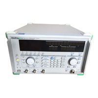
Anritsu MG3642A Operation Manual (212 pages)
Anritsu Synthesized Signal Generator Operation Manual
Brand:
Anritsu
| Category:
Test Equipment
| Size: 1 MB
Table of Contents
Operation Manual
1
Safety Symbols
2
Symbols Used in Manual
2
For Safety
3
Equipment Certificate
7
Notes on Export Management
8
CE Conformity Marking
10
Applied Standards
10
C-Tick Marking
12
Table of Contents
15
General
19
Brief Description
19
Section 3 Panel Layout
20
Operation Manual
20
Composition of Devices
21
Standard Composition
21
Options
22
Application Parts
23
Specifications
24
Precaution
31
Installation Precautions
31
Installation Site Environmental Conditions
31
Safety Measures
32
General Power Supply Safety Measures
32
Reverse Power Input to RF Output Connector
32
Mounting the MG3641A/MG3642A in the Frame
33
Preparation before Power-On
34
Connecting the Power Cord
35
Fuse Replacement
36
Panel Layout
37
Front Panel Layout
37
Rear Panel Layout
39
Panel Layout Diagram
40
Operating Instructions
41
Turning Power On/Off
41
Turning Power on
43
Turning Power off
44
Explanation of Screens
45
Initial Settings
46
Setting the Frequency
48
Displaying the Frequency Relative Value
49
Frequency Offset
50
Setting the Output Level
51
Displaying the Output Level Relative Value
52
Output Level Offset
53
Level Continuous Mode
54
Switching the Output Signal On/Off
55
Special Functions Related to Level
56
Setting the Modulation
58
Outline of Modulation
58
Setting the Modulation Function
59
Setting the Modulation Factor and Frequency Deviation
60
Setting Range of FM Frequency Deviation
61
Polarity of Modulation Signal
61
Pulse Modulation
62
Setting the Modulation Signal Source
64
Internal Modulation Signal (Int1)
64
Internal Modulation Signals (Int2, Int3)
65
External Modulation Signals (Ext1, Ext2)
66
Setting the AF Output
68
Outline of Memory Functions
70
Memory Functions
70
Storing in the Memory
70
Recalling Memory Contents
71
Clearing the Memory
73
Selecting the Memory Recall Mode
74
Sweep Functions
75
Outline of Sweep Functions
75
Setting and Executing the Sweep
76
Sweep Auxiliary Outputs
78
Trigger Functions
81
Outline of Trigger Function
81
Registering the Trigger Program
82
Executing the Trigger Program
83
Checking the Contents of the Trigger Program
84
Miscellaneous Functions
85
Setting Display On/Off
85
Setting Bell • Alarm On/Off
86
Setting Address and Only Mode of GPIB
87
Panel Lock
88
Removing Reverse Power Protection (RPP) Circuit Operation
89
Error Messages
90
Section 5 Measurement
93
Measurement
93
Measurement of Sensitivity
93
Measuring 20 Db NQ Sensitivity
94
Measuring 12 Db SINAD Sensitivity
95
Measuring the 1-Signal Selectivity
96
Measuring Selectivity Characteristics of the FM Receiver in 20 Db NQ Method
96
Measuring Spurious Response
99
Measuring the 2-Signal Sensitivity
101
Measuring the Sensitivity Blocking of the FM Receiver
101
Measuring the Cross-Modulation Characteristics
104
Section 6 Gpib
107
Gpib
107
Outline of GPIB
107
Overview
107
GPIB Functions
107
Setup Example
108
Standard
109
Device Message List
110
Outline
110
General Information on SCPI
110
Command Structure
110
Writing Commands
111
Compounding Commands
112
Parameter
113
Unit
113
Command Tree
114
Connecting the GPIB Cable
120
Device Message Format
121
Program Message Format
121
Response Message Format
124
Status Message
126
Status Register Configuration
126
IEEE488.2-Based Status Register
127
SCPI Standard Status Register
128
Reading, Writing, Clearing, and Resetting the Status Register
129
SCPI Error Messages
131
Initializing Device
133
Bus Initialization
133
Message Initialization
133
Device Initialization
133
Device State at Power-On
133
Detailed Description of Commands
134
Frequency Subsystem
134
Output Level Subsystem
138
AM Subsystem
144
FM Subsystem
145
PM Subsystem
147
Modulation Source Subsystem
148
MEMORY Subsystem
151
Display Subsystem
153
System Subsystem
154
Status Subsystem
155
IEEE488.2 Common Command
157
Sample Program
159
GPIB Command Interchange Function
162
Outline
162
Restrictions in Mg3633Acommand Interchange Mode
163
Restrictions in MG3631A/32A Command Interchange Mode
166
Section 7 Performance Test
169
Performance Test
169
Performance Test Required
169
Performance Test Device List
170
Performance Test
171
Output Frequency
172
Output Level Frequency Characteristics
173
Output Level Accuracy
174
FM Deviation and FM Distortion
176
AM Modulation Factor and am Distortion
178
Section 8 Calibration
181
Calibration
181
Calibration Required
181
Calibration Device List
181
Calibration
182
Storage and Transportation
185
Daily Servicing and Preventive Maintenance
185
Storage Precautions
185
Precautions before Storage
185
Recommended Storage Conditions
186
Repacking and Transportation
186
Repacking
186
Transportation
186
Appendix Ainitial Factory Settings
187
Appendix Bfunction-Key Transition
191
Appendix Cfront and Rear Panel Layout
197
Appendix D Index
201
Appendix E Performance Test Results Sheet
207
Appendix E Performance Test Result Sheet
207
Advertisement
Anritsu MG3642A Operation Manual (36 pages)
Synthesized Signal Generator, Option 23: Pattern Generator
Brand:
Anritsu
| Category:
Inverter
| Size: 0 MB
Table of Contents
Table of Contents
7
Section 1 Overview
9
Product Overview
9
Devices Configuration
9
Specifications
10
Section 2 Preparation before Use
11
Data and Clock Connectors Labeling
11
Connection
12
Section 3 Operation Overview
15
Section 4 Detailed Description
17
Delivery Mode
17
Data Output Method
21
Section 5 Remote Control by GPIB
23
Overview
23
Command Tree
23
Command Details
25
Data Write Details
30
Appendix Initialization
33
Anritsu MG3642A Operation Manual (18 pages)
Synthesized Signal Generator Option 22: FSK ENCODER
Brand:
Anritsu
| Category:
Test Equipment
| Size: 0 MB
Table of Contents
Safety Symbols
2
Table of Contents
7
1 Overview
9
Outline of the Product
9
Unit Configuration
9
Specifications
9
2 Preparation before Use
10
Attaching the Data and Clock Connector Labels
10
3 Outline of Operation
11
4 Detailed Description
13
Level FSK
13
5 Remote Control Using Gpib
14
Overview
14
Command Tree
15
Details of Commands
16
Appendix Settings at Shipment
17
Advertisement
Advertisement
Related Products
Anritsu MG3641A
Anritsu MG369 A Series
Anritsu MG3692A
Anritsu MG3691A
Anritsu MG3693A
Anritsu MG3694A
Anritsu MG3695A
Anritsu MG3696A
Anritsu MN9664A
Anritsu MU110010A
Anritsu Categories
Measuring Instruments
Test Equipment
Portable Generator
Control Unit
Thermometer
More Anritsu Manuals
Login
Sign In
OR
Sign in with Facebook
Sign in with Google
Upload manual
Upload from disk
Upload from URL