
Related Manuals for ANCA Motion AMD5x

Summary of Contents for ANCA Motion AMD5x
- Page 1 AMD5x Passive Infeed Unit and AMD5x Servo Drive - User Guide AMD5x Passive Infeed Unit and AMD5x Servo Drive - User Guide D-000129 Rev 09 ANCA MOTION D-000129 Rev 09...
- Page 2 AMD5x Passive Infeed Unit and AMD5x Servo Drive - User Guide Page intentionally left blank ANCA MOTION D-000129 Rev 09...
- Page 3 AMD5x Passive Infeed Unit and AMD5x Servo Drive - User Guide AMD5x Passive Infeed Unit and AMD5x Servo Drive - User Guide Some Important Links Related Manuals and Brochures Related Documentation Sales and Support Contact Information Product, Sales and Service Enquiries...
- Page 4 AMD5x Passive Infeed Unit and AMD5x Servo Drive - User Guide Page intentionally left blank ANCA MOTION D-000129 Rev 09...
- Page 5 AMD5x Passive Infeed Unit and AMD5x Servo Drive - User Guide Chapter Summaries Safety General Product safety information Introduction Target Audience, model applicability, help in reading the manual and related manuals/brochures Product Overview Features, operating principles, labels, connector overview Mechanical Installation...
- Page 6 AMD5x Passive Infeed Unit and AMD5x Servo Drive - User Guide Page intentionally left blank ANCA MOTION D-000129 Rev 09...
-
Page 7: Table Of Contents
AMD5x Passive Infeed Unit and AMD5x Servo Drive - User Guide Contents 1 Safety ................................. 1 General Safety ............................1 2 Introduction............................... 3 What This Chapter Contains ........................3 Purpose ..............................3 About The AMD5x Series Passive Infeed Units ..................3 About The AMD5x Series Servo Drives .................... - Page 8 AMD5x Passive Infeed Unit and AMD5x Servo Drive - User Guide 4 Mechanical Installation ..........................35 What This Chapter Contains ......................... 35 Pre Installation Checks.......................... 35 Requirements ............................35 4.3.1 Installation Site ........................35 4.3.2 Mounting ..........................36 4.3.3 Drive Array Mounting Options and Benefits ................37 4.3.4...
- Page 9 AMD5x Passive Infeed Unit and AMD5x Servo Drive - User Guide Motor Brake Connection........................73 5.7.1 Shielded Armature Cable with Brake ..................74 Motor Thermal Sensor........................... 74 5.8.1 Shielded Armature Cable with Thermal Sensor Schematic ............. 75 5.8.2 Shielded Armature Cable with Brake and Thermal Sensor ............. 76 Regeneration ............................
- Page 10 AMD5x Passive Infeed Unit and AMD5x Servo Drive - User Guide 8 Installation Checklist ............................99 What this Chapter Contains ........................99 Checklist ..............................99 9 PIU Operation..............................101 What this Chapter Contains ........................ 101 PIU Introduction ..........................101 PIU not Enabled ..........................102 Enabling the PIU ..........................
- Page 11 AMD5x Passive Infeed Unit and AMD5x Servo Drive - User Guide 10.5.8 Drive Physical Characteristics ................... 118 10.5.9 Capacitor Module Physical Characteristics ............... 118 10.6 Dimension Drawings ........................... 119 10.6.1 15kW and 24kW PIU Physical Dimensions ............... 119 10.6.2 15kW and 24kW PIU Mounting Hole Positions and Heatsink Cut-Out Specifications ..122 10.6.3...
-
Page 13: Safety
This manual and the warnings attached to the AMD5x only highlight hazards that can be predicted by ANCA Motion. Be aware they do not cover all possible hazards. ANCA Motion shall not be responsible for any accidents caused by the misuse or abuse of the device by the operator. - Page 14 Do not touch heatsinks during drive system function as they may be hot. Care must be taken to avoid burns. Warning: Insulation resistance testers (megohmmeter) are not to be used on AMD5x PIU and Servo Drives, as a false resistance reading and/or damage to the tested equipment may result. Refer 5.11 Checking the Insulation...
-
Page 15: Introduction
2.3 About The AMD5x Series Passive Infeed Units The AMD5x Passive Infeed Unit (PIU) is the power input component of the AMD5x system. The PIU converts AC mains into a DC supply which is distributed to the servo drives on common DC Bus. It is called “passive” because there is no regulation of the conversion (rectification) process, and no ability to regenerate excess energy back into the mains supply. -
Page 16: Piu Model Applicability
AMD5x Passive Infeed Unit and AMD5x Servo Drive - User Guide 2.6 PIU Model Applicability AMD5x Series PIU Catalogue Numbers are shown in Figure 2-1. AMD5x PIU is marked with an identification label. The Catalogue number is explained as follows:... -
Page 17: Drive Model Applicability
D: Recessed mounting H: High Overload Figure 2-2: AMD5x Series Servo Drive Catalogue number interpretation For any warranty work to be undertaken these labels must be readable and undamaged. Care should be taken to record these numbers in a separate register in the event of damage or loss. -
Page 18: Capacitor Module Model Applicability
AMD5x Passive Infeed Unit and AMD5x Servo Drive - User Guide 2.8 Capacitor Module Model Applicability AMD5x Series Capacitor Module Catalogue Numbers are shown in Figure 2-3. AMD5x Capacitor Module is marked with an identification label. The Catalogue number is explained as follows:... -
Page 19: Related Documents
Digital Servo Drive SoE Parameter Reference – Included with firmware bundle Digital Servo Drive Error Code Reference – Included with firmware bundle To obtain these documents, contact your local ANCA Motion sales office. See 12.3 Product, Sales and Service Enquiries. -
Page 20: Terms And Abbreviations
AMD5x Passive Infeed Unit and AMD5x Servo Drive - User Guide 2.11 Terms and Abbreviations Table 1: Terms and Abbreviations Acronym Description Φ Mains supply phase Ø Diameter Ω Ohms AIN / AI Analogue Input AOUT / AO Analogue Output... -
Page 21: Product Overview
Explanation of Labelling and Markings Electrical Connections 3.2 Features The AMD5x is a multi-axis servo drive system controlled by an external CNC via EtherCAT interface. Standard features include: Variable mounting options (Duct, Recessed, Wall Mount). Conformal Coating on Recessed and Wall Mount versions. -
Page 22: Amd5X Variant Identification
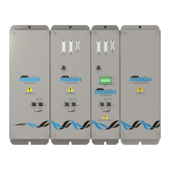
AMD5x Passive Infeed Unit and AMD5x Servo Drive - User Guide 3.3 AMD5x Variant Identification Table 2: AMD5x Variant Identification Duct Mount Drive Capacitor Module Wall Mount Drive Capacitor Module Recessed Mount Drive Capacitor Module ANCA MOTION D-000129 Rev 09... -
Page 23: Operating Principle
3.4 Operating Principle The simplified diagram of the AMD5x control is shown below. The 3 phase AC supply voltage is converted to DC, which is then distributed via a bus to each Drive. The number of drives is chosen by the customer. Each drive converts the DC into the required variable frequency AC voltage signal to drive each motor. -
Page 24: Piu
AMD5x Passive Infeed Unit and AMD5x Servo Drive - User Guide 3.5.1 The Passive Infeed Unit (PIU) primary function is to convert 3 phase mains into a filtered DC supply which is then distributed to the servo drives. The PIU also distributes the customer supplied 24 Vdc control voltage to all drives, and connects the EtherCAT master device to the PIU and Drive system. -
Page 25: Piu Connector Overview
Product Overview 3.6 PIU Connector Overview The top view of the AMD5x PIU is shown in Figure 3-4. Figure 3-4: Regenerative Brake Resistor (X1) and 3 Phase Mains + Earth Supply (X2) ANCA Motion D-000129 Rev 09... -
Page 26: X1 - Regenerative Brake Resistor
AMD5x Passive Infeed Unit and AMD5x Servo Drive - User Guide The bottom view of the AMD5x PIU is shown in Figure 3-5. Figure 3-5: Digital Input (X5), LED Supply (X6), and 24 Vdc Supply (X7) X1 – Regenerative Brake Resistor 3.6.1... -
Page 27: X2 - 3 Phase Mains + Earth Supply
3.6.3 Table 5: Digital Input Pin Assignment Connector Function Pin Number Label (Looking at bottom of PIU) SWITCH_RETURN Switch Input (N/C). 24 Vdc system SWITCH_24 VDC Mating Connector: Phoenix Plug 1910351, ANCA Part Number: ICN-3077-0875 ANCA Motion D-000129 Rev 09... -
Page 28: X6 - Led Supply
AMD5x Passive Infeed Unit and AMD5x Servo Drive - User Guide X6 – LED Supply 3.6.4 Table 6: LED Supply Connector Function Label Number Pin Assignment LED OUT - Provides LED OUT + EtherCAT brightness control for customer LED ring... -
Page 29: Drive Connector Overview
Product Overview 3.7 Drive Connector Overview The top view of the AMD5x Drive is shown in Figure 3-6 Figure 3-6: 24 Vdc Brake Connections (X10), 3 Phase Armature Supply (X11), Motor Temperature Sensor Input (X12) and Hiperface DSL Interface (X30) - Page 30 AMD5x Passive Infeed Unit and AMD5x Servo Drive - User Guide The front view of the AMD5x Drive is shown in Figure 3-7. Figure 3-7: Encoder Inputs (X13, X14), Probe Input (X15), Encoder CH1 Monitor Output (X16), EtherCAT In (X17), EtherCAT Out (X18), BiSS Encoder Monitor Output (X31) and BiSS/ABZ Encoder Input (X32)
-
Page 31: X10 - 24 Vdc Brake Connections
Table 11: Motor Temperature Sensor Input Pin Assignment Connector Function Pin Number Label (Looking at top of Drive) (KTY84/130 CATHODE) Connects to Motor Thermistor + (KTY84/130 ANODE) Mating Connector: Phoenix Plug Female 1910351, ANCA Part Number: ICN-3077-0875 ANCA Motion D-000129 Rev 09... -
Page 32: X13 - Encoder 1 Input
AMD5x Passive Infeed Unit and AMD5x Servo Drive - User Guide X13 – Encoder 1 Input 3.7.4 The drive supports 2 channels of 1Vpp encoders on channel 1 (Figure 3-8) and channel 2 (Figure 3-9). Brake Power (24V) Servo Motor... - Page 33 (Looking at front of Drive) REF1+ COS1- COS_COM1- SIN_COM1- SIN1- ENC1+5V Connects to 1 Vpp Analog Encoder REF1- COS1+ COS_COM1+ SHIELD SIN_COM1+ SIN1+ ENC1_0V CASE SHIELD Mating Connector: D-SUB 15-WAY Male with 4-40 UNC jack screws ANCA Motion D-000129 Rev 09...
-
Page 34: X14 - Encoder 2 Input
AMD5x Passive Infeed Unit and AMD5x Servo Drive - User Guide X14 – Encoder 2 Input 3.7.5 The drive supports 2 channels of 1Vpp encoders on channel 1 (Figure 3-8) and channel 2 (Figure 3-9). Brake Power (24V) Servo Motor... - Page 35 Pin Number Label (Looking at front of Drive) REF2+ COS2- SIN2- ENC2+5V Connects to 1 Vpp Analog Encoder REF2- COS2+ SHIELD SIN2+ ENC2_0V CASE SHIELD Mating Connector: D-SUB 15-WAY Male with 4-40 UNC jack screws ANCA Motion D-000129 Rev 09...
-
Page 36: X15 - Probe 1&2 Input, Probex +24 Vdc Probe/Proxy Feed
AMD5x Passive Infeed Unit and AMD5x Servo Drive - User Guide X15 – Probe 1&2 Input, ProbeX +24 Vdc Probe/Proxy Feed 3.7.6 Table 14: Probe Input +24 Vdc Probe/Proxy Feed Pin Assignment Connector Function Pin Number Label (Looking at front of Drive) -
Page 37: X16 - Encoder Monitor Output
KXE-1100-0010 Shielded Ethernet Cable Cat 5e SF/UTP 1 metre KXE-1100-0015 Shielded Ethernet Cable Cat 5e SF/UTP 1.5 metres KXE-1100-0030 Shielded Ethernet Cable Cat 5e SF/UTP 3 metres KXE-1100-0050 Shielded Ethernet Cable Cat 5e SF/UTP 5 metres ANCA Motion D-000129 Rev 09... -
Page 38: X30 - Hiperface Dsl Encoder Interface
AMD5x Passive Infeed Unit and AMD5x Servo Drive - User Guide X30 – Hiperface DSL Encoder Interface 3.7.9 Typical drive with Hiperface DSL encoder is shown in Figure 3-10 Brake Power (24V) HDSL Probe DC Bus DC Bus EtherCAT In... - Page 39 The connector-plug has a Spring Cage format and supports the termination of a wire gauge range of 16 – 24 AWG with a wire strip length of 10 mm, or ferrules (including a plastic sleeve) with a cross sectional area range of 0.14 – 0.75 mm ANCA Motion D-000129 Rev 09...
-
Page 40: X32 Biss/Abz Encoder Input
AMD5x Passive Infeed Unit and AMD5x Servo Drive - User Guide 3.7.10 X32 BiSS/ABZ Encoder Input Typical drive with BiSS or ABZ encoder is shown in Figure 3-11 Brake Power (24V) Servo Motor Probe BiSS/ABZ DC Bus DC Bus EtherCAT In... - Page 41 Pin Number Label (Looking at front of Drive) BiSS_+5V BiSS_MA+/A+ BiSS_MA-/A- BiSS_+5V BiSS_MO-/Z- Connects to BiSS or ABZ digital encoder BiSS_+0V BiSS_SLO+/B+ BiSS_SLO-/B- BiSS_MO+/Z+ CASE SHIELD Mating Connector: D-SUB 9-WAY Male with 4-40 UNC jack screws ANCA Motion D-000129 Rev 09...
-
Page 42: X31 Biss Encoder Functional Safety Output
AMD5x Passive Infeed Unit and AMD5x Servo Drive - User Guide 3.7.11 X31 BiSS Encoder Functional Safety Output The BiSS encoder signals can be monitored by an external functional safety device. Table 19: BiSS Encoder Monitor Output Pin Assignment Connector... -
Page 43: X20 - Io Interface
Polarisation is provided for each mating connector-plug via the inclusion of factory fitted Coding Keys (Red) on pins 12 and 13 of the IO Interface connector-header (X20); the two supplied connector-plugs are provided with the associated pin keys removed. ANCA Motion D-000129 Rev 09... - Page 44 AMD5x Passive Infeed Unit and AMD5x Servo Drive - User Guide Figure 3-12: AMD5x Drive IO Interface Connector ANCA MOTION D-000129 Rev 09...
-
Page 45: Led Display And Control Panel - Piu
Product Overview 3.7.13 LED Display and Control Panel - PIU The AMD5x series PIUs are fitted with a bi-colour status LED as shown in the following figure: Table 21: LED Display and Control Panel - PIU PIU Display LED Status Blue... -
Page 46: Led Display And Control Panel - Drive
AMD5x Passive Infeed Unit and AMD5x Servo Drive - User Guide 3.7.14 LED Display and Control Panel - Drive The AMD5x series Drives are fitted with a bi-colour status LED as shown in the following figure: Table 22: LED Display and Control Panel - Drive Drive Display LED Status Blue... -
Page 47: Mechanical Installation
The maximum recommended operating altitude is 1000m above sea level. Consult ANCA Motion for ratings at higher altitudes. The AMD5x must be installed in a cabinet or enclosure of rating IP54 or higher. Higher IP ratings may be required depending on application. ... -
Page 48: Mounting
Painted panels are not to be used. If any AMD5x 35A (125mm wide) drives are to be installed, these must be mounted adjacent to the PIU. All 24 Vdc ribbon cable configurations require this installation method. Refer 11.4 24 Vdc Ribbon Cable. -
Page 49: Drive Array Mounting Options And Benefits
Heatsinks are not visible. Allows easier maintenance of the internal electrical cabinet operating conditions by moving the majority of the losses to an isolated area behind the gear tray. Refer to 10.5.3 Installation and Operation more details ANCA Motion D-000129 Rev 09... -
Page 50: Heatsink Cooling With External Cabinet Air Using Duct Mount Fitment
Heatsink Cooling with Internal Cabinet Air Using Duct Mount Fitment The duct mounted AMD5x PIU and Drives MUST use a duct (air tunnel) which can be installed in a cabinet where the cooling duct air is supplied from internal cabinet air (see Figure 4-3). - Page 51 The PIU and Drives are mounted on a small gear tray which also supports the cooling duct and fan mounting (see Figure 4-4). Figure 4-3: AMD5x system with internal cabinet air supplying cooling duct Figure 4-4: AMD5x cooling duct and gear tray with internal cabinet air supplying cooling duct ANCA Motion D-000129 Rev 09...
-
Page 52: Example Cooling Duct Design
AMD5x Passive Infeed Unit and AMD5x Servo Drive - User Guide 4.3.6 Example Cooling Duct Design A suitable cooling duct system can be created with folded sheet-metal as per Figure 4-5. Figure 4-5: Cooling Duct with typical dimensions The duct must have no air leaks, and is mounted onto the rear of the gear tray with PIU and Drives. - Page 53 Mechanical Installation Figure 4-8: Duct entry view A suitable fan module kit to mount on the duct end can be supplied by ANCA Motion. See 11.6 Cooling Duct Fan Kit. The two fans should be fitted inside the duct end as per Figure 4-9, and sealed to maximise air flow.
-
Page 54: Heatsink Cooling - Wall Mount Fitment
AMD5x Passive Infeed Unit and AMD5x Servo Drive - User Guide A correctly selected fan kit module and duct design provide sufficient air flow across the drive heatsinks to allow full operation within the acceptable temperature range. If air flow is insufficient the heat sink temperature may increase to the point that the PIU or Drive will signal an error and cease to provide energy to the motor. -
Page 55: Cabinet Cooling
4.3.9.1 Mounting of Drives for Effective Cooling Inside the Electrical Cabinet: The AMD5x PIU and drives require 100mm clearance on the top and bottom as shown in Figure 4-12, to allow connector access and provide sufficient ventilation. There is no clearance requirement for the sides of PIU provided adjacent equipment does not exceed the product temperature specifications. -
Page 56: Installation
4.4.1 Installation Order If any AMD5x 35A or 35AH (125mm wide) Drives are to be installed, these must be mounted adjacent to the PIU. All 24 Vdc ribbon cable configurations are based on this installation order. Refer 11.4 24 Vdc Ribbon Cable ... - Page 57 When installing the recessed mount PIU, be careful not to damage the pull tabs on the fan housing when the product is inserted into the gear tray slot. Refer to Figure 4-15 Figure 4-15: Mechanical Mounting of PIU Recessed Mount ANCA Motion D-000129 Rev 09...
-
Page 58: Mounting A Drive
AMD5x Passive Infeed Unit and AMD5x Servo Drive - User Guide 4.4.3 Mounting a Drive The following sections show the drive mounting holes for the Duct mount (Figure 4-16), Wall mount (Figure 4-17) and Recessed mount (Figure 4-18) variants. The installation is intended to insert the bottom screw first, before the drive is lifted into position. The screw should not be made tight, but screwed with about 5mm of thread exposed. - Page 59 Mechanical Installation Figure 4-17: Mechanical Mounting of a Drive Wall Mount Figure 4-18: : Mechanical Mounting of a Drive Recessed Mount ANCA Motion D-000129 Rev 09...
-
Page 60: Mounting A Capacitor Module
AMD5x Passive Infeed Unit and AMD5x Servo Drive - User Guide 4.4.4 Mounting a Capacitor Module The following sections show the capacitor module mounting holes for the Duct mount (Figure 4-19), Wall mount (Figure 4-20) and Recessed mount (Figure 4-19) variants. - Page 61 Mechanical Installation Figure 4-20: Mechanical Mounting of Capacitor Module for a Wall Mount ANCA Motion D-000129 Rev 09...
-
Page 62: System Installation
AMD5x Passive Infeed Unit and AMD5x Servo Drive - User Guide 4.4.5 System Installation The AMD5x PIU and Drives must be installed as a system with the following steps. 4.4.5.1 Protective Cover Installation Fit the Protective Cover to the last Drive or Capacitor Module on the right to prevent accidental contact with the... - Page 63 Protective Cover to the Capacitor Module in the array Figure 4-24: Fitted high voltage DC Busbars and PE Wire Harnesses Figure 4-24-A: Close-up view of DC Busbars pointing to the LEFT ANCA Motion D-000129 Rev 09...
- Page 64 AMD5x Passive Infeed Unit and AMD5x Servo Drive - User Guide 4.4.5.3 Fit Drive Controller PCBAs Prior to fitting the controller cards to the drives, connect the two ribbon cables for each drive to the controller PCBA as shown in Figure 4-25.
- Page 65 4-28. Ensure the cover flanges are located within the folded tabs on the chassis as shown in Figure 4-29. Captive screws located on the four corners of each of the front covers Figure 4-28: FItted Front Covers on PIU, Drives and Capacitor Module ANCA Motion D-000129 Rev 09...
-
Page 66: Uninstalling The Piu And Drive System
4.4.7 Uninstalling the PIU or one Drive from the Array The following steps are required when removing a PIU or Drive from an AMD5x Drive System. Ensure mains power has been isolated from the drives. Refer to 5.3.1 Power Isolation. -
Page 67: Fan Housing Assembly Replacement
Figure 4-32. For the 35A and 35AH Drives there are three fan connections. For the 20A Drive there are two fan connections. For the 12A / 6A / 3A Drives there is one fan connection. ANCA Motion D-000129 Rev 09... - Page 68 AMD5x Passive Infeed Unit and AMD5x Servo Drive - User Guide Figure 4-32: Disconnect and remove the fan plug(s) from the Drive PCBA Pull on the handles as shown in Figure 4-32 to disengage the fan housing assembly from the unit. Carefully remove the fan housing assembly completely and then the whole fan housing assembly can be discarded.
-
Page 69: Installing The New Fan Housing Assembly
Ensure the fan wires are not damaged during this process. Once the fan housing assembly has been fully inserted, check the plastic snaps are located into their slots in the chassis. Figure 4-34: Routing the fan wires through the chassis slot into the Drive ANCA Motion D-000129 Rev 09... -
Page 70: Fan Harness Routing And Connection
AMD5x Passive Infeed Unit and AMD5x Servo Drive - User Guide 4.5.3 Fan Harness Routing and Connection For the PIU, route the fan harness as shown in Figure 4-35 through the cut-out hole in the PCB board. Before fixing the wire harness to the chassis wall with a new cable tie from the box, ensure the plug is fully inserted and plugged into the connector on the PCB board and there is no strain on the harness. -
Page 71: Power Wiring
EMC compliant installation. The AMD5x PIUs and Drives are suitable for use on supplies of installation overvoltage Category III, according to IEC 61800-5-1. This means they may be connected permanently to the supply at its origin in a building, but for machine installations closer to primary distribution supply (overhead cables etc.) additional over-voltage... -
Page 72: Connection Of Piu To Grounded Systems (Tn Or Tt)
5.2.2 Connection of PIU to Grounded Systems (TN or TT) The AMD5x PIU is designed to operate with grounded TN & TT systems where the three phase supply is from a transformer with a grounded star point (Refer to Figure 5-1). -
Page 73: Residual Current Detection (Rcd) Protection
This DC current can reduce the ability of a type A or AC type RCD to trip. Warning: The AMD5x system is designed for category C3, and is not intended to be used on a low-voltage public network which supplies domestic premises. -
Page 74: Power Disconnect And Protection Devices
Safety of Machinery standard EN 60204-1 and local regulations. The AMD5x PIU must have suitable input power protection for the three phase input. This protection must conform to the requirements and applicable safety regulations of the region of operation. An appropriate approval for switches is IEC 60947-2 and for circuit breakers IEC 60947-3. -
Page 75: Power Isolation
Mains Contactors When the AMD5x Passive Infeed Unit (PIU) is connected directly to a 3 phase mains AC supply with no isolation contactors, the Drive Array DC Bus & Servo Drive motor armature cable outputs are constantly at a high voltage even when the PIU is not enabled. - Page 76 In multiple drive installations, each motor must be individually wired to its corresponding X11 plug PE point. Do not daisy chain PE connections from one Drive to the next or to a separate earth bar. The AMD5x system uses an internal PE Busbar which is connected to the customer supply with PIU (X2) and then distributed to all drives.
-
Page 77: Installations Conforming To The Emc Directive
For this reason, the EMC conformance of the system as a whole must be confirmed by the customer in accordance to the appropriate standards for their application and market. Converter Cabinet Line Filter Line Reactor AMD5x PIU AMD5x Drive Motor Cable Distribution Transformer leak Heatsink... -
Page 78: Harmonics And Reactive Power Compensated Supplies
AMD5x Passive Infeed Unit and AMD5x Servo Drive - User Guide 5.5.1 Harmonics and Reactive Power Compensated Supplies The PIU input diode bridge is a non-linear load to the mains supply and generates low frequency conducted harmonic effects in the frequency range up to 9 kHz. The non-linear currents cause non-sinusoidal voltage drops across the internal resistance of the mains supply transformer and therefore distort the voltage at the point of common coupling (PCC). -
Page 79: Installation Guidelines Of Emc Components
Drive connector PE terminal (X11). Do not connect directly to the mains supply protective earth as this will increase EMC noise. Minimise unshielded Motor lengths AMD5x Drive Earth shield connected 360° to gear tray or armature bracket Figure 5-7: Motor connections and shielding... -
Page 80: Motor Circuit Contactors
AMD5x Passive Infeed Unit and AMD5x Servo Drive - User Guide 5.6.1 Motor Circuit Contactors A motor circuit contactor may be installed if required by local codes or for safety reasons. The motor circuit contactor isolates the motor fully from the Drive to allow maintenance and may form part of a safety system. -
Page 81: Motor Power Cable Shielding
5.6.4 Motor Power Cable Shielding Motor power cables from the AMD5x drive to the motor must have braided outer shields to minimize effects to other equipment. The cable shield minimizes radiated electromagnetic noise which may be coupled into nearby conductors, and the shield provides a low impedance path for common mode noise currents back to the drive via correct shield grounding. -
Page 82: Motor Signal Cable Shielding
11.8.9 Motor Power Cable Shield Clamps for details of the recommended Hiperface DSL Segment EMC Shield Clamp). All AMD5x Drives use the same EMC Clamp for the Outer Shield (ICN-3049-0522) and the same EMC Clamp for the Hiperface DSL Segment Shield (ICN-3049-0523). - Page 83 Power Wiring Figure 5-11: Hiperface DSL Cable Assembly: Drive Interface The nominal placement of the EMC Shield Clamps is dependent on the AMD5x Drive variant (refer to Figure 5-12): Duct/Recessed Mount: The Outer Shield and Hiperface DSL Segment Shield EMC Clamps must be co- located at the Gear Tray DIN Rail, which would normally both be placed 100 mm (D1, D3) above the top face of the Drive.
-
Page 84: Shielded Hiperface Dsl Armature Cable
AMD5x Passive Infeed Unit and AMD5x Servo Drive - User Guide 5.6.10 Shielded Hiperface DSL Armature Cable Shielded Hiperface DSL armature cable schematic for Gamma Motors is shown in Figure 5-13 with connector pin identification. K5B-DSMD cable variant catalogue numbers can be found in 11.8.7 Shielded Hiperface DSL... -
Page 85: Motor Brake Connection
The relay is activated, causing the brake to be disengaged. The AMD5x drive contains a configurable brake release delay after the motor is enabled to prevent undesired AMD5x Series Servo Drive – SoE Configuration Guide movement, refer to the for more information. -
Page 86: Shielded Armature Cable With Brake
Figure 5-17: K5B-BSMD schematic and connector pin identification Motor Thermal Sensor The AMD5x Drive employs a fully isolated input circuit to receive the signal from a KTY84/130 temperature sensor, which is embedded in the motor windings. This input circuit complies with LVD requirements to assume that the temperature sensor itself may under some circumstances be live at the full armature voltage potential. -
Page 87: Shielded Armature Cable With Thermal Sensor Schematic
Figure 5-19:AMD5x Drive motor thermal sensor installation For ANCA Motion Motors fitted with Hiperface DSL Encoders, the Temperature Sensor information is communicated to the AMD5x Drive through the Hiperface DSL Encoder communications channel, rather than via the separate Thermal Sensor interface connector. -
Page 88: Shielded Armature Cable With Brake And Thermal Sensor
AMD5x Passive Infeed Unit and AMD5x Servo Drive - User Guide 5.8.2 Shielded Armature Cable with Brake and Thermal Sensor Shielded armature cable with brake and thermal sensor schematic for Beta and Gamma Motors is shown in Figure 5-22 with connector pin identification. K5B-SSMD cable variant catalogue numbers can be found in 11.8.5... -
Page 89: Regeneration
36kW, and have a continuous rms resistor dissipation of 3kW. In selecting and sizing the Brake Resistor, BOTH the peak power capability AND the continuous rms capability must be satisfied. AMD5x Drive(s) AMD5x PIU Regenerative Brake Resistor... -
Page 90: Capacitor Module
5.9.2 Capacitor Module The AMD5x Capacitor module is used to increase the DC Bus capacitance and allows regenerative energy to be stored and reused. Each module has a capacitance of 2115µF, with greater energy storage capability at lower mains voltage. The modules are connected directly to the AMD5x system DC Bus. No pre-charging is necessary as the PIU is capable of soft charging the DC Bus with the capacitor modules connected. -
Page 91: Regenerative Energy Calculations
10.4.1 AMD5x PIUs 10.4.2 Drives for drive capacitance specifications. AMD5x PIU(705µF) + 2 x 35A drives(270µF each) + 1 x 20A drive(135µF) + 1 x 12A drive(135µF) , thus total bus capacitance = 1,515µF Mains 3 phase line-line voltage: 380V, thus V... -
Page 92: Dc Busbar And Pe Terminals
1 Safety The AMD5x PIU and Drives utilise a common DC Bus where power is supplied from the PIU and distributed to all Drives connected on the same bus. The Protective Earth bus runs parallel to the DC Bus and uses the same busbars to connect between Drives and PIU. -
Page 93: Control Wiring
24 Vdc cable should be appropriately insulated for 1000V. 6.3 24 Vdc Control Circuit Supply The AMD5x requires an external 24 Vdc supply to power all control circuits in the PIU and Drives. This supply is Refer 3.6.5 X7 – 24 Vdc connected to PIU with connector X7. -
Page 94: Fan Operation On Wall And Recessed Mount Drives
AMD5x Passive Infeed Unit and AMD5x Servo Drive - User Guide The current demand of the 24 Vdc supply must be sized on the number and types of Drives, types of encoders, and additional loads such as probes. A conservative estimate is 0.3 A for the PIU and 1 A for each Drive. This is based on two high current encoders and both Proximity Switches being used. -
Page 95: Ethernet Interface
AMD5x supports the EtherCAT protocol with ‘Servo Profile over EtherCAT’ (SoE). This protocol provides deterministic communication over a standard 100Mbit/s (100Base-TX) Fast Ethernet (IEEE802.3) connection. This makes it suitable for the transmission of control and feedback signals between the AMD5x and other EtherCAT enabled controllers. - Page 96 EtherCAT OUT 6.4.2.3 EtherCAT Cables To connect the AMD5x drive and PIU to other EtherCAT devices the following types of cables must be used with Ethernet 8P8C modular connectors. They are commonly referred to as “RJ45 shielded patch leads”. Table 27: EtherCAT Cables...
-
Page 97: Motor Encoder Feedback
(casing) of the D-SUB connector. NOTE: Poor or absent shielding connections is the main cause of noise problems within a system. The AMD5x Drives are particularly robust, and have characteristically low noise in Encoder signal processing, but good shielding is nevertheless essential in achieving this robustness. -
Page 98: Hiperface Dsl Encoder
3.7.9 X30 – Hiperface DSL Encoder Interface. The ANCA Motion Hiperface DSL Motor Cable Assembly range is designed to be used with an AMD5x Drive fitted with HDLS Encoder support and an ANCA Motion Motor fitted with a Hiperface DSL Encoder. Two exposed shielded braid areas on the Hiperface DSL Cable Assembly support the separate clamping of the Outer Shield and Hiperface DSL Segment Shield at the Drive Gear Tray, adjacent to the top face of the Drive –... -
Page 99: Biss Rs-422 Physical Interface
The BiSS Functional Safety Monitor Clock(MA) and Data(SL) signals are buffered with a maximum propagation delay of 12ns, which can be compensated in the BiSS Functional Safety Monitor. Figure 6-3: AMD5x Drive BiSS RS-422 connections The RS-422 cables must have the following characteristics: ... -
Page 100: Probe Inputs
Feed for pin assignment. The D-SUB 9-WAY X15 connector on the AMD5x Drive has provision for two separate Probe Inputs and a dedicated 24 Vdc power source intended for use with Probes or Proxy switches. A feature of the 24 Vdc power source not only means that probe/proxy wiring is simplified, but more importantly, noise free probe/proxy operation can be achieved since the 24 Vdc feed is “clean”, and free of noise usually present on general use 24... -
Page 101: Io Interface
Control Wiring 6.7 IO Interface The AMD5x Servo Drive with an integral IO Interface provides a core Servo Drive function along with a generic Input/Output (IO) Interface to support customer IO requirements. The Drive is used in Servo Motor Drive Systems requiring additional IO control and detection for external transducers and other control/measurement equipment. -
Page 102: X20 - Io Interface For The Associated Pin Assignment
All Positive and Negative References are functionally isolated (between SELV circuits) from the rest of the AMD5x Drive system. It should be noted that a common Negative Reference (0 Vdc) could be used between the AMD5x Drive (system) and the IO interface, but this could lead to noise related performance issues on some subsystems. -
Page 103: General Purpose Digital Output
An isolated Positive Reference between +5 to +24 Vdc is connected to the Positive Reference (VREFHS) for this subsystem. A typical wiring diagram of the High Speed Digital Output subsystem is shown in Figure 6-4: Typical Wiring Diagram: DO-GP and DO-HS. Figure 6-4: Typical Wiring Diagram: DO-GP and DO-HS ANCA Motion D-000129 Rev 09... -
Page 104: Digital Input
AMD5x Passive Infeed Unit and AMD5x Servo Drive - User Guide 6.7.6 Digital Input An isolated Positive Reference of +24 Vdc is connected to Positive Reference (VREF24 V) for this subsystem. A typical wiring diagram of a Digital Input subsystem is shown in Figure 6-5: Typical Wiring Diagram: DI-GP. -
Page 105: Analog Input
(P/N) and connecting the other channel input to the appropriate Reference (usually the Negative Reference). A typical wiring diagram of the Analog Input subsystem is shown in Figure 6-6: Typical Wiring Diagram: AI. Figure 6-6: Typical Wiring Diagram: AI ANCA Motion D-000129 Rev 09... -
Page 106: Analog Output
AMD5x Passive Infeed Unit and AMD5x Servo Drive - User Guide 6.7.8 Analog Output The Analog Output subsystem has one Single Ended Output referenced to the common Negative Reference. A Transducer with a Differential Input format could be interfaced to the Analog Output by connecting the Channel Output Signal to the appropriate Transducer Differential Input (P/N) and connecting the other Transducer Differential Input to the Negative Reference. -
Page 107: Ethercat Configuration
Reference, please contact Product, Sales and Service Enquiries The AMD5x PIU Frame Packet Mapping includes information on the Input and Output types. This chapter also describes the Boolean Inputs and Outputs, and Integer Inputs for when used with ANCA CNCs. When being... -
Page 108: Ethercat Error Indicator
AMD5x Passive Infeed Unit and AMD5x Servo Drive - User Guide 7.2.2 EtherCAT Error Indicator The normal (working) state of the ERROR LEDs is Off. Table 30: EtherCAT ERROR LED Indicator states State of LED Description A critical communication or application error has occurred... -
Page 109: Piu Frame Packet Mapping
Warning: Heatsink fan is either not connected or not rotating correctly. **For the 15kW PIU IDC+ = 130A (Load current), and IDC- = -50A (Regen current). For the 24kW PIU IDC+ = 240A (Load current), and IDC- = -100A (Regen current). ANCA Motion D-000129 Rev 09... -
Page 110: Inputs - Analogue Variables
AMD5x Passive Infeed Unit and AMD5x Servo Drive - User Guide Inputs – Analogue Variables 7.3.2 The EtherCAT Frame Packet for analogue variables which can be monitored is shown in Table Table 34: Input Analogue variables. LABEL DESCRIPTION UNIT SIZE... -
Page 111: Installation Checklist
Appropriate supply fuses and disconnect devices have been installed. See 5.2 Mains Power Supply An appropriate inductor must be installed between the AMD5x PIU input (X2) and 3 phase mains AC supply. See 5.5 Installations Conforming to the EMC Directive recommended inductor ratigns and installation. - Page 112 AMD5x Passive Infeed Unit and AMD5x Servo Drive - User Guide implemented Excess lengths of Hiperface DSL motor cables are not coiled Hiperface DSL motor cables are separated from each other No power factor compensation capacitors have been connected to the motor cable.
-
Page 113: Piu Operation
The PIU also distributes the customer supplied 24 Vdc control voltage to all drives, provides a LED power supply, and interfaces via EtherCAT. Figure 9-1: Block diagram of the PIU system ANCA Motion D-000129 Rev 09... -
Page 114: Piu Not Enabled
AMD5x Passive Infeed Unit and AMD5x Servo Drive - User Guide 9.3 PIU not Enabled When the PIU is not Enabled, the thyristors in the half bridge (see Figure 9-1: Block diagram of the PIU system) will be turned off and not allow charging of the DC Bus. The thyristors control power flow to the DC Bus but do not provide electrical isolation from the mains supply. -
Page 115: Capacitor Charging
If load is applied during the Regenerative Brake Resistor test or capacitor charging stage, the test may fail or the error E_LoVolt =1 may occur. During operation of applied load regeneration may occur when DC Bus rises above 806V , and the status bit Rgn=1 will be set. Refer Regeneration. ANCA Motion D-000129 Rev 09... -
Page 116: Disabling The Piu
This is a measurement of customer 24 Vdc supply with a range of 0V to 48.18V. An error is generated when the voltage is less than 19V and greater than 29V, and the error E_24 V=1 is set. When the control voltage drops below 19V, the AMD5x Drive(s) will shut down. 9.5.4 Grid Frequency Measurement of customer mains frequency begins after the PIU has been enabled. -
Page 117: Fault Detection Bits
AC voltage between DC Bus and customer connection. 14. W_Gnd Protective Earth is too large. AMD5x Drive has phase to PE short circuit which does not trip drive overcurrent. The LED driver has detected no LEDs Check LEDs and wiring circuit connected to 15. -
Page 118: Led Supply
9.6 LED Supply The AMD5x PIU has an additional LED driver feature where the brightness to a customer string of 6 LEDs can be controlled via EtherCAT Output Analogue variable LED_Intensity. The LEDs are connected to X6. Refer 3.6.4... -
Page 119: Technical Data
PIU heat-sink temperature limit 70° C Drive Adjustable dynamic current limiting Drive Adjustable continuous over-current monitoring Drive Adjustable instantaneous over-current monitoring Drive amplifier junction temperature estimation and protection for motor low rotation frequency and standstill operation ANCA Motion D-000129 Rev 09... -
Page 120: Self-Protection Features
AMD5x Passive Infeed Unit and AMD5x Servo Drive - User Guide Attribute Qualification 10.2.3 Self-Protection Features PIU DC Bus overcurrent PIU DC Bus over and under voltage Motor overload Yes, see AMD5x Series Servo Drive –SoE Configuration Guides for adjustment. -
Page 121: Interface Specifications
5.19V DC, regulated Supply Voltage Range 5.10V DC to 5.25V DC Supply Voltage Monitoring Maximum Supply Current per Channel 500mA Maximum Supply Current total, both Channels 500mA Short Circuit Protection Yes, 950mA maximum (internally limited) ANCA Motion D-000129 Rev 09... -
Page 122: Biss/Abz Encoder
AMD5x Passive Infeed Unit and AMD5x Servo Drive - User Guide Attribute Qualification 10.3.5 Hiperface DSL Encoder Number of Hiperface DSL Channels per AMD5x Drive Encoder Cable Format Two wire (integrated data and power signals) Signal Bandwidth 9.375 Mbps 7 Vdc ≤ Vsupply ≤ 12 Vdc at 250 mA... -
Page 123: Io Interface
500 mA at +24 Vdc per digital output Multiple Output State Configuration Multiple digital outputs can be turned ON concurrently Output Architecture Push Pull Load Type Resistive Output Setting: Enable Control Enable control per output: Normal (Active), high impedance ANCA Motion D-000129 Rev 09... - Page 124 AMD5x Passive Infeed Unit and AMD5x Servo Drive - User Guide Attribute Qualification Switching Frequency Range DC to 20 kHz PWM Output Mode: Switching Frequency Range 1 Hz to 5 kHz PWM Output Mode: Pulse Width 0.2 to 20 mS PWM Output Mode: Pulse Width: Resolution µ...
-
Page 125: Electrical Specifications
Technical Data 10.4 Electrical Specifications Table 40: Electrical Specifications 10.4.1 AMD5x PIUs Attribute Symbol 15kW PIU 24kW PIU 3 Phase Input Voltage 380 to 480 VAC LL-(3 Φ) 3 Phase Mains Voltage Fluctuation ± 10% δ ƒ 3 Phase Input Frequency... -
Page 126: Drives
AMD5x Passive Infeed Unit and AMD5x Servo Drive - User Guide Attribute Symbol Qualification 10.4.2 Drives Current Rating 35AH DC Voltage 600V Nominal, 500 to 850V range Max. Line to Line rms output voltage 370V AC @ 600V DC Bus Input LL-(3 Φ) -
Page 127: Temperature Derating
Figure 10-1: Drive continuous rms output current derating The air inlet temperature to the heatsink of the duct mounted drives is limited to 0⁰C to 45⁰C to enable the full load current to be delivered. ANCA Motion D-000129 Rev 09... -
Page 128: Environmental Specifications
AMD5x Passive Infeed Unit and AMD5x Servo Drive - User Guide 10.5 Environmental Specifications Table 41: Environmental Specifications Attribute Qualification 10.5.1 Storage Ambient Temperature -20 to +65° C Relative Humidity 5 to 90% Storage dust and solid particles exposure limit... -
Page 129: Duct Mount Cooling
Technical Data Attribute Qualification 10.5.4 Duct Mount Cooling AMD5x Product Variant 15kW 24kW 35AH Drive Drive Drive Drive Drive Drive Heat-sink losses to duct at 60 W 75 W 42 W 70 W 131 W 194 W 298 W 297 W... -
Page 130: Physical Characteristics
AMD5x Passive Infeed Unit and AMD5x Servo Drive - User Guide Attribute Qualification 10.5.6 Physical Characteristics Degree of Ingress Protection (IP Rating) IP 20 in accordance with EN60529 Mounting position in Operation Vertical 10.5.7 15kW and 24kW PIU Physical Characteristics... -
Page 131: Dimension Drawings
10.6.1 15kW and 24kW PIU Physical Dimensions Physical dimensions for Duct mount ( Figure 10-2), Wall mount( Figure 10-3) and Recessed mount( Figure 10-4) for PIU. Figure 10-2: 15kW and 24kW PIU dimensions Duct mount ANCA Motion D-000129 Rev 09... - Page 132 AMD5x Passive Infeed Unit and AMD5x Servo Drive - User Guide Figure 10-3: 15kW and 24kW PIU dimensions Wall mount ANCA MOTION D-000129 Rev 09...
- Page 133 Technical Data Figure 10-4: 15kW and 24kW PIU dimensions Recessed mount ANCA Motion D-000129 Rev 09...
-
Page 134: 15Kw And 24Kw Piu Mounting Hole Positions And Heatsink Cut-Out Specifications
AMD5x Passive Infeed Unit and AMD5x Servo Drive - User Guide 10.6.2 15kW and 24kW PIU Mounting Hole Positions and Heatsink Cut-Out Specifications Mounting hole positions and heatsink cut outs for Duct( Figure 10-5) and Wall( Figure 10-6) mount PIU. - Page 135 Technical Data Figure 10-6: Mounting holes for PIU Wall mount For Recessed Mount heatsink hole cut out details refer to Figure 10-26 Figure 10-30. ANCA Motion D-000129 Rev 09...
-
Page 136: And 35Ah Drive Mounting Hole Positions And Physical Dimensions
AMD5x Passive Infeed Unit and AMD5x Servo Drive - User Guide 10.6.3 35A and 35AH Drive Mounting Hole Positions and Physical Dimensions Mounting hole positions and physical dimensions for Duct mount( Figure 10-7), Duct mount with IO interface( Figure 10-8), Wall mount(... - Page 137 Technical Data Figure 10-8: 35A and 35AH Drive dimensions (with IO Interface) Duct mount ANCA Motion D-000129 Rev 09...
- Page 138 AMD5x Passive Infeed Unit and AMD5x Servo Drive - User Guide Figure 10-9: 35A and 35AH Drive dimensions (without IO Interface) Wall mount ANCA MOTION D-000129 Rev 09...
- Page 139 Technical Data Figure 10-10: 35A and 35AH Drive dimensions (with IO Interface) Wall mount ANCA Motion D-000129 Rev 09...
- Page 140 AMD5x Passive Infeed Unit and AMD5x Servo Drive - User Guide Figure 10-11: 35A and 35AH Drive dimensions (without IO Interface) Recessed mount ANCA MOTION D-000129 Rev 09...
- Page 141 Technical Data Figure 10-12: 35A and 35AH Drive dimensions (with IO Interface) Recessed mount ANCA Motion D-000129 Rev 09...
-
Page 142: 6A, 12A & 20A Drive Mounting Hole Positions And Physical Dimensions
AMD5x Passive Infeed Unit and AMD5x Servo Drive - User Guide 10.6.4 3A, 6A, 12A & 20A Drive Mounting Hole Positions and Physical Dimensions Mounting hole positions and physical dimensions for Duct mount( Figure 10-13), Duct mount with IO interface (... - Page 143 Technical Data Figure 10-14: 3A, 6A, 12A & 20A Drive dimensions (with IO Interface) Duct mount ANCA Motion D-000129 Rev 09...
- Page 144 AMD5x Passive Infeed Unit and AMD5x Servo Drive - User Guide Figure 10-15: 3A, 6A, 12A & 20A Drive dimensions (without IO Interface) Wall mount ANCA MOTION D-000129 Rev 09...
- Page 145 Technical Data Figure 10-16: 3A, 6A, 12A & 20A Drive dimensions (with IO Interface) Wall mount ANCA Motion D-000129 Rev 09...
- Page 146 AMD5x Passive Infeed Unit and AMD5x Servo Drive - User Guide Figure 10-17: 3A, 6A, 12A & 20A Drive dimensions (without IO Interface) Recessed mount ANCA MOTION D-000129 Rev 09...
- Page 147 Technical Data Figure 10-18: 3A, 6A, 12A & 20A Drive dimensions (with IO Interface) Recessed mount ANCA Motion D-000129 Rev 09...
-
Page 148: Drive Mounting Hole Positions And Heatsink Cut-Out Specifications
AMD5x Passive Infeed Unit and AMD5x Servo Drive - User Guide 10.6.5 Drive Mounting Hole Positions and Heatsink Cut-Out Specifications Mounting hole positions and heatsink cut outs for Duct (Figure 10-19) and Wall ( Figure 10-20) mount 3A, 6A, 12A, 20A, 35A and 35AH Drives. - Page 149 Technical Data Figure 10-20: Mounting hole & cut-out specifications for 3A, 6A, 12A, 20A, 35A & 35AH Wall mount Drives For Recessed Mount heatsink hole cut out details refer to Figure 10-26 Figure 10-30. ANCA Motion D-000129 Rev 09...
-
Page 150: Capacitor Module Physical Dimensions
AMD5x Passive Infeed Unit and AMD5x Servo Drive - User Guide 10.6.6 Capacitor Module Physical Dimensions Physical dimensions of Duct & Recessed ( Figure 10-21) and Wall (Figure 10-22) mount Capacitor Modules. Figure 10-21: Capacitor Module dimensions for Duct and Recessed mount... -
Page 151: Capacitor Module Mounting Hole Positions
10.6.7 Capacitor Module Mounting Hole Positions The capacitor module has the same mounting hole positions as the 15kW and 24kW PIU. See section 10.6.1 15kW and 24kW PIU Physical Dimensions No heatsink cut-out is required. ANCA Motion D-000129 Rev 09... -
Page 152: Piu, 35A, 20A, And 12A/6A/3A Drives And Capacitor Module Mounting Hole Positions
AMD5x Passive Infeed Unit and AMD5x Servo Drive - User Guide 10.6.8 PIU, 35A, 20A, and 12A/6A/3A Drives and Capacitor Module Mounting Hole Positions Mouting hole positions for Duct, Wall and Recessed mount Array PIU, 35A, 20A, 12A/6A/3A Drives and... -
Page 153: Piu, 35A, 20A And 12A/6A/3A Drives Heat Sink Cut-Out Specifications
Duct mount 20A Drive 35A Drive 12A/6A3A Drive Capacitor Module Figure 10-25: PIU, 35A, 20A and 12A/6A/3A drives heatsink cut-outs and Capacitor Module mounting hole positions in an array Wall mount ANCA Motion D-000129 Rev 09... - Page 154 AMD5x Passive Infeed Unit and AMD5x Servo Drive - User Guide 20A Drive 12A/6A3A Drive 35A Drive Capacitor Module Figure 10-26: PIU, 35A, 20A and 12A/6A/3A drives heatsink cut-outs and Capacitor Module mounting hole positions in an array Recessed mount...
-
Page 155: Piu, 20A And 12A/6A/3A Drives And Capacitor Module Mounting Hole Positions
Mounting hole positions for Duct, Wall and Recessed mount Array PIU, 20A, and 12A/6A/3A Drives and Capacitor Module(Figure 10-27). 20A Drive 12A/6A3A Drive Capacitor Module Figure 10-27: PIU, 20A and 12A/6A/3A drives and Capacitor Module mounting hole positions for Duct, Wall and Recessed mounted Array ANCA Motion D-000129 Rev 09... -
Page 156: Piu, 20A And 12A/6A/3A Drives Heat Sink Cut-Out Specifications
AMD5x Passive Infeed Unit and AMD5x Servo Drive - User Guide 10.6.11 PIU, 20A and 12A/6A/3A Drives Heat Sink Cut-Out Specifications Heat sink cut-out specifications for Duct (Figure 10-28), Wall (Figure 10-29) and Recessed (Figure 10-30) mount PIU, 20A/12A/6A drives and Capacitor Module. - Page 157 Technical Data 20A Drive 12A/6A3A Drive Capacitor Module Figure 10-29: PIU, 20A and 12A/6A/3A drives heatsink cut-outs and Capacitor Module hole mounting hole positions in an array Wall mount ANCA Motion D-000129 Rev 09...
- Page 158 AMD5x Passive Infeed Unit and AMD5x Servo Drive - User Guide 20A Drive 12A/6A3A Drive Capacitor Module Figure 10-30: PIU, 20A and 12A/6A/3A drives heatsink cut-outs and Capacitor Module hole mounting hole positions in an array Recessed mount ANCA MOTION...
-
Page 159: Materials
Technical Data 10.7 Materials Information regarding the materials used in the AMD5x PIU and Drives is shown in Table 42: AMD5x PIU and Drive MaterialsTable 42. Table 42: AMD5x PIU and Drive Materials Enclosure: The AMD5x Drive and PIU chassis (main, sub, and fan) are stainless steel 304 with a silver paint finish. -
Page 160: Standards Conformity
AMD5x Passive Infeed Unit and AMD5x Servo Drive - User Guide 10.8 Standards Conformity Information regarding the AMD5x PIU and Drives standards conformity is shown in Table 43. Table 43: AMD5x PIU and Drive Standards Conformity Marking & Applicable Certification... -
Page 161: Ethercat Conformance Marking
The AMD5x PIUs and Drives are intended for use as Category 3 PDS, and have been tested and certified to comply for use within what 61800-3 defines as the second environment. The AMD5x PIUs and Drives comply with the standard with the following provisions: The motor and control cables are selected according the specifications given in this manual. -
Page 162: Fcc Marking
A FCC mark is attached to the Product Label in order to verify that the unit meets the relevant Electromagnetic Compliance (EMC) standards of the Federal Communications Commission. All AMD5x PIUs and 20A, 12A, 6A , 3A drive variants, and capacitor modules are FCC compliant. ANCA MOTION... -
Page 163: Accessories
Accessories 11 Accessories 11.1 What This Chapter Contains This chapter contains information on accessories options available for the AMD5x system. For additional details, please refer to 12.3 Product, Sales and Service Enquiries 11.2 EMI Filter ANCA Part Number Description ICN-3096-0036 Schaffner 30A RFI filter. -
Page 164: Ethercat ® Cables
AMD5x Passive Infeed Unit and AMD5x Servo Drive - User Guide ® 11.5 EtherCAT Cables Product code KXE-1100-0020 EtherCAT cable Cable length: Examples: Cable type: 0002: 0.2 Metre 1 – CAT5e PVC SF/UTP 0015: 1.5 Metres 0030: 3.0 Metres Connector type: Reserved 1 –... -
Page 165: Regen Resistor
Regen Resistor over-temperature switch, open above 70°C, TO-220 package 11.7.3 Regen Resistor with Enclosure and Over-Temperature Switch ANCA Part Number Description Aluminium Housed Braking Resistor, 36Ω ± 10%, 375W ICN-3009-0850 180°C temperature switch, 24kW 1s. ANCA Motion D-000129 Rev 09... -
Page 166: Cables
AMD5x Passive Infeed Unit and AMD5x Servo Drive - User Guide 11.8 Cables 11.8.1 Shielded Encoder Cable Beta/Gamma Motors Table 47: Shieled Encoder Cables for Beta Motors Catalogue Number Length K5B-FSMD-020 K5B-FSMD-030 K5B-FSMD-050 K5B-FSMD-100 11.8.2 Shielded Armature Cable for Beta/Gamma Motors... -
Page 167: Shielded Armature Cables For Beta/Gamma Motors With Brake And Thermal Sensor
Description Hebotec part SKDZ4 7-18 ICN-3049-0522 (for cable shield diameters 7-18 mm) Hebotec part SKDZ4 3-12 ICN-3049-0523 (for cable shield diameters 3-12 mm) Note: Cable shield diameter is typically 2mm less than cable Outer Diameter. ANCA Motion D-000129 Rev 09... -
Page 168: Piu And Drive Connectors
AMD5x Passive Infeed Unit and AMD5x Servo Drive - User Guide 11.9 PIU and Drive Connectors Table 56: PIU and Drive Connectors Catalogue Description Chapter Reference Number 3.6.1 X1 – Regenerative Brake ICN-3077-1670 15kW and 24kW PIU Regen Connector 2-Way Resistor 3.6.2... -
Page 169: Additional Information
4 Mechanical Installation for site requirements, tools, and installation and uninstallation information. There are no internal adjustments inside the AMD5x. For any repairs please contact our nearest office or agent. Refer to section 12.3 Product, Sales and Service Enquiries. ANCA Motion... -
Page 170: Product, Sales And Service Enquiries
AMD5x Passive Infeed Unit and AMD5x Servo Drive - User Guide 12.3 Product, Sales and Service Enquiries If you require assistance for installation, training or other customer support issues, please contact the closest ANCA Motion Customer Service Office in your area for details.
Need help?
Do you have a question about the AMD5x and is the answer not in the manual?
Questions and answers