Sign In
Upload
Manuals
Brands
Ametek Manuals
Measuring Instruments
Western Research IPS-4
Ametek Western Research IPS-4 Manuals
Manuals and User Guides for Ametek Western Research IPS-4. We have
6
Ametek Western Research IPS-4 manuals available for free PDF download: User Manual, Essential Health & Safety Requirements
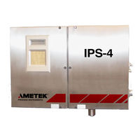
Ametek Western Research IPS-4 User Manual (238 pages)
Dual Bench (UV / IR) Analyzer Zone 1 / Division 2
Brand:
Ametek
| Category:
Measuring Instruments
| Size: 7.31 MB
Table of Contents
Offices
2
Table of Contents
3
Electrical Safety
9
Grounding
9
Safety Notes
9
Personnel and Equipment Safety Information
10
Warnings
10
Cautions
12
Environmental Information (WEEE)
13
UV Source Lamps Disposal
13
Warning Labels
13
Electromagnetic Compatibility (EMC)
14
Special Warnings and Information
15
EU Declaration of Conformity
16
Warranty and Claims
18
Chapter 1 Overview
19
Optical Bench Configurations
19
Basic Analytical Theory (Optical Bench)
19
Flow Diagram
19
Calculation Flow
20
Dispersive Ultraviolet/Visible (DUVV) Spectrometer
22
Basic Analytical Theory
22
Optical Bench Design
22
UV Specifications
23
Wavelength Ranges
23
Wavelength Accuracy
23
Wavelength Resolution
23
Analyzer Range
23
Photometric Range
23
Photometric Noise
23
Non-Dispersive Infrared (NDIR) Photometer
24
Basic Analytical Theory
24
Optical Bench Design
24
NDIR Specifications
25
Wavelength Ranges
25
Photometric Range
25
Photometric Noise
25
Sample System
25
Electronics
26
Classified, Hazardous Area Protection Components and Functions
27
Supplemental Information - Where Can I Find It
30
Chapter 2 Specifications
31
Analyzer Specifications
31
Analytes
31
Response Linearity
31
Measurement Accuracy
31
Repeatability
31
Linearity
31
Stability
31
24-Hour Zero Drift
32
Inputs
32
Outputs
32
Sample System Limits
33
Sample Pressure
33
Oven/Sample System Enclosure Temperature
33
Sample Transport
33
Instrument Air Requirements
33
Sample Fluid Flow Rate
33
Electrical Requirements
34
Power Consumption
34
Heated Sample Line
34
Supply Voltage
34
Cell Construction
34
Pressure Input Signals
34
On-Board Temperature Sensor
34
Environmental
35
Ambient Temperature
35
Humidity
35
Pollution Degree
35
Maximum Altitude
35
Installation Category II
35
Enclosure Material
35
Ingress Protection
35
Physical Dimensions
35
Approvals and Certifications
36
Special Condition of Use
37
ATEX and Iecex Certificates and Analyzer Markings
38
IPS-4 Dual Bench Analyzer ATEX Certificate
38
IPS-4 Dual Bench Analyzer Marking
41
IPS-4 Dual Bench Analyzer Iecex Certificate
42
Chapter 3 Installation and Start-Up
49
Safety Considerations
50
Pre-Installation Requirements
50
Storage Prior to Installation
50
Uncrating and Inspecting the Analyzer
51
General Installation Information
51
Tools, Equipment, and Supplies Required
52
Installing the Mechanical Components
54
Mounting the Analyzer
54
Location and Environment
54
Installing the Optical Bench-UV Assembly
58
Installing the Optical Bench IR Assembly
59
Installing the Sample System
61
Installing the Sample Probe/Sample Tap
62
Installing and Connecting the Sample and Vent Lines
62
Installing and Connecting the Instrument Air/Zero Fluid Line
63
Installing and Connecting the Purge Fluid Line
65
Installing the Calibration (Span) Fluid Line (Optional)
67
Connecting I/O Signals, Alarm Relay Contacts, and AC Power
68
Electrical Connections
68
Permanent Ethernet Cable Connections (Optional)
69
Start-Up and Verification
71
Purged Analyzers
71
Powering up the Analyzer
74
Start-Up Diagnostic Checklist
83
Sample System Leak Check
85
Manually Zeroing the Analyzer Sample System
87
Adjusting the Zero/Span Fluid Flow Rate
88
Adjusting the Sample Flow Rate
89
Setting Sample Response Time
90
Normal Operation
91
Recording Initial Readings
91
Recording Initial Sample Response Time
91
Analyzer Configuration
92
Chapter 4 Controller / User Interface
93
Introduction to the User Interface Panel
94
User Interface Panel Components
94
Special Software Characters
96
Working from the User Interface Panel - Conditions and Messages
97
Summary of Analyzer Operation
98
Working in the Main Menus
99
HOME Menu Screen
99
System Status Messages (HOME Screen)
101
Alarm and Warning Notification (HOME Screen)
102
ALARMS and WARNINGS Menu Screen
103
Viewing Current Alarms and Warnings
103
Viewing Logged Alarms and Warnings
104
STATUS Menu Screen
105
SETUP Menu Screen
107
Calibration Control Screen
108
Calibration Settings Screen
108
Flush Times
111
Calibration Valves
112
Calibration Actions Screen
113
Manually Starting a Zero Calibration
114
Manually Starting a Span Calibration
115
Manually Starting a Neutral Density Filter Verification
116
Neutral Density Filter Verification Diagnostic Chart
117
Relay Setup Screens
118
Current Output Setup Screens
121
Setpoints
123
Diagnostics Screen
125
System Settings Screen
126
The System Settings Screen (Figure 4-31) Allows the User to View And/Or Setup Analyzer System Parameters
126
Login/Set Passwords Screen
127
Changing the Password
129
Locking the Password
129
Removing the Password
129
Backup/Restore Settings Screen
130
Backing up Analyzer Configuration Settings
131
Restoring Analyzer Configuration Settings
131
Ethernet Network Screen
133
Customization Screen
136
Modbus Screen
138
Chapter 5 Maintenance and Troubleshooting
141
Safety Considerations
141
Maintenance
143
Preventive Maintenance
143
Analyzer Preventive Maintenance Schedule
144
Expo Technologies Minipurge ® System with Etimer (Optional) Preventive Maintenance Schedule
146
Locating a Plug in the Sample System
147
Detecting a Plug in the Sample System
147
Changing out Replaceable Parts
148
Tools, Equipment, and Supplies Required for Maintenance
149
Measuring Cell Preventive Maintenance
151
Replacing the Xenon (UV) Flash Lamp Assembly
159
Replacing the Infrared (IR) Source Assembly
163
Troubleshooting and Diagnostics
166
Alarm Conditions and Corrective Action
167
Analyzer Reset
171
Chapter 6 Service and Parts
173
Technical Support
173
Returning Equipment
174
AMETEK Service and Aftermarket Sales Support
175
Recommended Spare Parts
176
Measuring Cell Assembly Spare Parts
176
Optical Bench Assembly Spare Parts
176
Spare Analyzer Fuses
177
Chapter 7 User Web Interface
179
Introduction to the Web Interface
180
Web Interface Components
181
Working from the Web Interface - Conditions and Messages
181
HOME Menu Screen
182
ALARMS Menu Screen
183
Current Alarms and Warnings
183
Logged Alarms and Warnings
184
Alarm and Warning Notification
184
TRENDS Menu Screen
185
Parameters
186
Intervals
186
SPECTRA Menu Screen
187
Viewing Spectral Data
187
SETTINGS Menu Screen
188
Calibration Settings Screen
189
Actions Screen
190
Current Output Screen
191
Relay Setup Screens
192
Network and Modbus Screen
193
System and Customization Screen
194
Analytes Screen
195
Limits Screen
196
Diagnostics Screen
197
Save/Restore Files Screen
198
Advertisement
Ametek Western Research IPS-4 User Manual (200 pages)
Western Research Full Spectrum Option Zone 1
Brand:
Ametek
| Category:
Measuring Instruments
| Size: 5.89 MB
Table of Contents
Offices
2
Table of Contents
3
Safety Notes
8
Electrical Safety
8
Grounding
8
Personnel and Equipment Safety Information
9
Warnings
9
Cautions
10
Electromagnetic Compatibility (EMC)
12
Special Warnings and Information
13
Equipment Used in Class I, Division 1 and Zone 1 Hazardous Locations
13
Warranty and Claims
14
Overview
15
Optical Bench Configurations
15
Basic Analytical Theory (Optical Bench)
15
Flow Diagram
15
Calculation Flow
16
Dispersive Ultraviolet/Visible (DUVV) Spectrometer
18
Basic Analytical Theory
18
Optical Bench Design
18
UV Specifications
19
Wavelength Ranges
19
Wavelength Accuracy+/- 0.5 Nm
19
Wavelength Resolution3 Nm
19
Analyzer Rangeppm to 100 %, Depending on the Application
19
Photometric Range
19
Photometric Noise
19
Optical Bench Design
20
NDIR Specifications
21
Wavelength Ranges
21
Photometric Noise
21
Sample System
21
Electronics
21
Classified, Hazardous Area Protection Components and Functions
23
Specifications
25
Analyzer Specifications
25
Analytes
25
Response Linearity
25
Measurement Accuracy
25
Repeatability
25
Linearity
25
Stability
25
24-Hour Zero Drift
25
Inputs
25
Sample System Limits
26
Sample Pressure
26
Oven/Sample System Enclosure Temperature
26
Sample Transport
26
Instrument Air Requirements
26
Sample Fluid Flow Rate
26
Electrical Requirements
26
Power Consumption
26
Heated Sample Line
27
Supply Voltage
27
Cell Construction
27
Pressure Input Signals
27
Environmental
27
Ambient Temperature
27
Humidity
27
Pollution Degree 2
27
Maximum Altitude
27
Installation Category II
27
On-Board Temperature Sensor
28
Physical Dimensions
28
Analyzer Markings
29
Installation & Start-Up
31
Safety Considerations
32
Pre-Installation Requirements
33
Storage Prior to Installation
33
Uncrating and Inspecting the Analyzer
33
General Installation Information
34
Tools, Equipment, and Supplies Required for Installation
34
Installing the Mechanical Components
37
Mounting the Analyzer
37
Location and Environment
37
To Mount the Analyzer
40
Installing the Optical Bench-UV Assembly
40
Installing the Optical Bench IR Assembly
42
Installing the Sample System
43
Installing the Sample Probe/Sample Tap
44
Installing and Connecting the Sample and Vent Lines
44
Installing and Connecting the Instrument Air/Zero Fluid Line
45
Installing and Connecting the Purge Fluid Line
47
Installing the Calibration (Span) Fluid Line (Optional)
48
Connecting I/O Signals, Alarm Relay Contacts, and AC Power
50
Electrical Connections
50
Permanent Ethernet Cable Connections (Optional)
51
Start-Up and Verification
53
Powering up the Analyzer
53
Start-Up Diagnostic Checklist
60
Sample System Leak Check
62
Manually Zeroing the Analyzer Sample System
63
Adjusting the Zero/Span Fluid Flow Rate
64
Adjusting the Sample Flow Rate
64
Setting Sample Response Time
65
Normal Operation
66
Recording Initial Readings
66
Recording Initial Sample Response Time
66
Analyzer Configuration
67
Controller / User Interface
69
Introduction to the User Interface Panel
70
User Interface Panel Components
70
Special Software Characters
72
Working from the User Interface Panel - Conditions and Messages
73
Summary of Analyzer Operation
74
Working in the Main Menus
75
HOME Menu Screen
75
System Status Messages (HOME Screen)
77
Alarm and Warning Notification (HOME Screen)
78
ALARMS and WARNINGS Menu Screen
79
Viewing Current Alarms and Warnings
79
Viewing Logged Alarms and Warnings
80
STATUS Menu Screen
81
SETUP Menu Screen
83
Calibration Control Screen
84
Calibration Valves
87
Calibration Actions Screen
88
Relay Setup Screens
90
Current Output Setup Screens
93
Setpoints
95
Diagnostics Screen
96
System Settings Screen
98
Login/Set Passwords Screen
98
Backup/Restore Settings Screen
100
Ethernet Network Screen
103
Customization Screen
106
Modbus Screen
107
Maintenance & Troubleshooting
109
Safety Considerations
109
Maintenance
110
Preventive Maintenance
110
Analyzer Preventive Maintenance Schedule
111
Before Performing Maintenance
113
Locating a Plug in the Sample System
114
Detecting a Plug in the Sample System
114
Changing out Replaceable Parts
115
Tools, Equipment, and Supplies Required for Maintenance
115
Measuring Cell Preventive Maintenance
118
Xenon Flash Lamp Assembly Replacement
125
Troubleshooting and Diagnostics
128
Alarm Conditions and Corrective Action
129
Analyzer Reset
133
Service & Parts
135
Technical Support
135
Returning Equipment
136
AMETEK Service & Aftermarket Sales Support
137
Recommended Spare Parts
138
Measuring Cell Assembly Spare Parts
138
Optical Bench Assembly Spare Parts
138
Spare Analyzer Fuses
139
Spare Battery, MCU Board
139
User Web Interface
141
Introduction to the Web Interface
142
Web Interface Components
143
Working from the Web Interface - Conditions and Messages
143
HOME Menu Screen
144
ALARMS Menu Screen
145
Current Alarms and Warnings
145
Logged Alarms and Warnings
146
Alarm and Warning Notification
146
TRENDS Menu Screen
147
Parameters
148
Intervals
148
SPECTRA Menu Screen
149
Viewing Spectral Data
149
SETTINGS Menu Screen
150
Calibration Settings Screen
151
Actions Screen
152
Current Output Screen
153
Relay Setup Screens
154
Network & Modbus Screen
155
System & Customition Screen
156
Analytes Screen
157
Limits Screen
158
Diagnostics Screen
159
Save/Restore Files Screen
160
Ametek Western Research IPS-4 User Manual (196 pages)
Full Spectrum Option General Purpose/Division 2
Brand:
Ametek
| Category:
Measuring Instruments
| Size: 5.7 MB
Table of Contents
Offices
2
Table of Contents
3
Safety Notes
8
Electrical Safety
8
Grounding
8
Personnel and Equipment Safety Information
9
Warnings
9
Cautions
10
Electromagnetic Compatibility (EMC)
12
Special Warnings and Information
13
Warranty and Claims
14
Overview
15
Optical Bench Configurations
15
Basic Analytical Theory (Optical Bench)
15
Flow Diagram
15
Calculation Flow
16
Dispersive Ultraviolet/Visible (DUVV) Spectrometer
18
Basic Analytical Theory
18
Optical Bench Design
18
UV Specifications
19
Wavelength Ranges
19
Wavelength Accuracy+/- 0.5 Nm
19
Wavelength Resolution3 Nm
19
Analyzer Rangeppm to 100 %, Depending on the Application
19
Photometric Range
19
Photometric Noise
19
Optical Bench Design
20
Ndir
21
Wavelength Ranges
21
Photometric Noise
21
Sample System
21
Electronics
21
Classified, Hazardous Area Protection Components and Functions
23
Specifi Cations
25
Analyzer Specifications
25
Analytes
25
Response Linearity
25
Measurement Accuracy
25
Repeatability
25
Linearity
25
Stability
25
24-Hour Zero Drift
25
Inputs
26
Outputs
26
Sample System Limits
26
Sample Pressure
26
Oven/Sample System Enclosure Temperature
26
Sample Transport
27
Instrument Air Requirements
27
Sample Fluid Flow Rate
27
Electrical Requirements
27
Power Consumption
27
Heated Sample Line
28
Supply Voltage
28
Cell Construction
28
Pressure Input Signals
28
Environmental
28
Ambient Temperature
28
Humidity
28
Pollution Degree 2
28
Maximum Altitude
28
Installation Category II
29
Enclosure Material
29
Ingress Protection
29
On-Board Temperature Sensor
29
Physical Dimensions
29
Approvals and Certifications
30
Installation & Start-Up
31
Safety Considerations
32
Pre-Installation Requirements
33
Storage Prior to Installation
33
Uncrating and Inspecting the Analyzer
33
General Installation Information
34
Tools, Equipment, and Supplies Required for Installation
34
Installing the Mechanical Components
35
Mounting the Analyzer
35
To Mount the Analyzer
37
Installing the Optical Bench-UV Assembly
37
Installing the Optical Bench IR Assembly
40
Installing the Sample System
42
Installing the Sample Probe/Sample Tap
42
Installing and Connecting the Sample and Vent Lines
43
Installing and Connecting the Instrument Air/Zero Fluid Line
44
Installing the Calibration (Span) Fluid Line (Optional)
45
Connecting I/O Signals, Alarm Relay Contacts, and AC Power
46
Electrical Connections
46
Permanent Ethernet Cable Connections (Optional)
47
Start-Up and Verification
48
Powering up the Analyzer
48
Start-Up Diagnostic Checklist
55
Sample System Leak Check
56
Manually Zeroing the Analyzer Sample System
57
Adjusting the Zero/Span Fluid Flow Rate
58
Adjusting the Sample Flow Rate
58
Setting Sample Response Time
59
Normal Operation
60
Recording Initial Readings
60
Recording Initial Sample Response Time
60
Analyzer Configuration
61
Controller / User Interface
63
Introduction to the User Interface Panel
64
User Interface Panel Components
64
Special Software Characters
66
Working from the User Interface Panel - Conditions and Messages
67
Summary of Analyzer Operation
68
Working in the Main Menus
68
HOME Menu Screen
68
System Status Messages (HOME Screen)
71
Alarm and Warning Notification (HOME Screen)
72
ALARMS and WARNINGS Menu Screen
73
Viewing Current Alarms and Warnings
73
Viewing Logged Alarms and Warnings
74
STATUS Menu Screen
75
SETUP Menu Screen
77
Calibration Control Screen
78
Calibration Valves
81
Calibration Actions Screen
81
Relay Setup Screens
84
Current Output Setup Screens
87
Setpoints
89
Diagnostics Screen
90
System Settings Screen
92
Login/Set Passwords Screen
92
Backup/Restore Settings Screen
94
Ethernet Network Screen
97
Customization Screen
100
Modbus Screen
101
Maintenance & Troubleshooting
103
Safety Considerations
103
Maintenance
104
Preventive Maintenance
104
Analyzer Preventive Maintenance Schedule
105
Before Performing Maintenance
107
Locating a Plug in the Sample System
107
Detecting a Plug in the Sample System
107
Changing out Replaceable Parts
109
Tools, Equipment, and Supplies Required for Maintenance
110
Measuring Cell Preventive Maintenance
112
Infrared Source Assembly Replacement
119
Xenon Flash Lamp Assembly Replacement
123
Replacing the MCU Battery
125
Troubleshooting and Diagnostics
127
Alarm Conditions and Corrective Action
129
Analyzer Reset
133
Service & Parts
135
Technical Support
135
Returning Equipment
136
AMETEK Service & Aftermarket Sales Support
137
Recommended Spare Parts
138
Measuring Cell Assembly Spare Parts
138
Optical Bench Assembly Spare Parts
138
Spare Analyzer Fuses
139
Spare Battery, MCU Board
139
User Web Interface
141
Introduction to the Web Interface
142
Web Interface Components
143
Working from the Web Interface - Conditions and Messages
143
HOME Menu Screen
144
ALARMS Menu Screen
145
Current Alarms and Warnings
145
Logged Alarms and Warnings
146
Alarm and Warning Notification
146
TRENDS Menu Screen
147
Parameters
148
Intervals
148
SPECTRA Menu Screen
149
Viewing Spectral Data
149
SETTINGS Menu Screen
150
Calibration Settings Screen
151
Actions Screen
152
Current Output Screen
153
Relay Setup Screens
154
Network & Modbus Screen
155
System & Customition Screen
156
Analytes Screen
157
Limits Screen
158
Diagnostics Screen
159
Save/Restore Files Screen
160
Advertisement
Ametek Western Research IPS-4 User Manual (178 pages)
Infrared Zone 1/Division 1
Brand:
Ametek
| Category:
Measuring Instruments
| Size: 4.57 MB
Table of Contents
Offices
2
Table of Contents
3
Electrical Safety
8
Grounding
8
Safety Notes
8
Personnel and Equipment Safety Information
9
Warnings
9
Cautions
10
Warning Labels
11
Environmental Information (WEEE)
11
Electromagnetic Compatibility (EMC)
12
Special Warnings and Information
13
Warranty and Claims
14
Chapter 1 Overview
17
Principles of Operation
17
Basic Analytical Theory
17
The Implementation
18
Optical System and Measurement
18
Sample System
19
Electronics
20
Classified, Hazardous Area Protection Components and Functions
21
Analyzer Electronics and Sample System Features
23
Chapter 2 Specifications
25
Methodology
25
Wavelength Ranges
25
Analyzer Range
25
Photometric Range
25
Analyzer Specifications
26
Analytes
26
Response Time
26
Measurement Accuracy
26
Repeatability
26
Linearity
26
Stability
26
24-Hour Zero Drift
26
Inputs
27
Outputs
27
Sample System Limits
27
Oven/Sample System Enclosure Temperature
27
Sample Pressure
27
Sample Transport
28
Instrument Air Requirements
28
Zero Fluid
28
Sample Fluid Flow Rate
28
Electrical Requirements
29
Power Consumption
29
Supply Voltage
29
Measuring Cell Construction
29
Pressure Input Signals
29
Environmental
30
Ambient Temperature
30
Enclosure Material
30
Humidity
30
Ingress Protection
30
Installation Category II
30
Maximum Altitude
30
Pollution Degree
30
On-Board Temperature Sensor
30
Physical Dimensions
31
Approvals and Certifications
31
Chapter 3 Installation & START-UP
33
Safety Considerations
34
Pre-Installation Requirements
35
Storage Prior to Installation
35
Uncrating and Inspecting the Analyzer
35
General Installation Information
36
Tools, Equipment, and Supplies Required for Installation
36
Installing the Mechanical Components
39
Mounting the Analyzer
39
Location and Environment
39
Installing the Optical Bench Assembly
43
Installing the Sample System
45
Installing the Sample Probe/Sample Tap
45
Installing and Connecting the Sample and Vent Lines
46
Installing and Connecting the Instrument Air/Zero Fluid Line
47
Installing and Connecting the Purge Fluid Line
49
Installing the Calibration (Span) Fluid Line (Optional)
50
Connecting I/O Signals, Alarm Relay Contacts, and AC Power
52
Electrical Connections
52
Permanent Ethernet Cable Connections (Optional)
53
Start-Up and Verification
55
Powering up the Analyzer
55
Start-Up Diagnostic Checklist
62
Sample System Leak Check
64
Manually Zeroing the Analyzer Sample System
65
Adjusting the Zero/Span Fluid Flow Rate
66
Adjusting the Sample Flow Rate
66
Setting Sample Response Time
67
Normal Operation
68
Recording Initial Readings
68
Recording Initial Sample Response Time
68
Analyzer Configuration
69
Chapter 4 Controller / USER Interface
71
Introduction to the User Interface Panel
72
User Interface Panel Components
72
Special Software Characters
74
Working from the User Interface Panel - Conditions and Messages
75
Summary of Analyzer Operation
76
Working in the Main Menus
77
HOME Menu Screen
77
System Status Messages (HOME Screen)
79
Alarm and Warning Notification (HOME Screen)
80
ALARMS and WARNINGS Menu Screen
81
Viewing Current Alarms and Warnings
81
Viewing Logged Alarms and Warnings
82
STATUS Menu Screen
83
SETUP Menu Screen
85
Calibration Control Screen
86
Calibration Settings Screen
86
Flush Times
88
Calibration Fluid Concentration
89
Calibration Screen
90
Manually Starting a Span Calibration
91
Manually Starting a Zero Calibration
91
Relay Setup Screens
93
Current Output Setup Screens
95
Setpoints
97
Diagnostics Screen
98
Login/Set Passwords Screen
100
System Settings Screen
100
Changing the Password
101
Backup/Restore Settings Screen
102
Locking the Password
102
Removing the Password
102
Backing up Analyzer Configuration Settings
103
Restoring Analyzer Configuration Settings
103
Ethernet Network Screen
105
System Screen
107
Customization Screen
108
Modbus Screen
109
Chapter 5 Maintenance & Troubleshooting
111
Safety Considerations
111
Maintenance
112
Preventive Maintenance
112
Analyzer Preventive Maintenance Schedule
113
Before Performing Maintenance
115
Detecting a Plug in the Sample System
116
Locating a Plug in the Sample System
116
Preventing a Plug in the Sample System (Gas Applications)
117
Changing out Replaceable Parts
118
Tools, Equipment, and Supplies Required for Maintenance
119
Measuring Cell Preventive Maintenance
121
Replacing the MCU Battery
132
Troubleshooting and Diagnostics
135
Alarm Notification - Viewing Alarms on the User Interface Panel
135
Viewing Current Alarm Messages
136
Viewing Historical Alarm Messages
136
Alarm Conditions and Corrective Action
137
Analyzer Reset
141
Ametek Western Research IPS-4 User Manual (170 pages)
Western Research Analyzer Fiber Optic UV/VIS Option General Purpose
Brand:
Ametek
| Category:
Measuring Instruments
| Size: 4.3 MB
Table of Contents
Table of Contents
3
Safety Notes
8
Electrical Safety
8
Grounding
8
Personnel and Equipment Safety Information
9
Cautions
10
Electromagnetic Compatibility (EMC)
12
Special Warnings and Information
13
Equipment Used in Class I, Division 2 Hazardous Locations
13
Warranty and Claims
14
Overview
17
Optical Bench Configurations
17
Basic Analytical Theory (Optical Bench)
17
Flow Diagram
17
Calculation Flow (SOFTWARE VERSION 3.0)
18
Dispersive Ultraviolet/Visible (DUVV) Spectrometer
20
Basic Analytical Theory
20
Optical Bench Design
20
UV Specifi Cations
21
Wavelength Ranges
21
Wavelength Accuracy +/- 0.5 Nm
21
Wavelength Resolution 3 Nm
21
Analyzer Range Ppm to 100 %, Depending on the Application
21
Photometric Range the Photometric Absorbance Range Is Dependent on Wavelength
21
Photometric Noise the Photometric Noise Is Dependent on Wavelength.typi- Cally +/- 0.001 AU
21
Electronics
22
Classified, Hazardous Area Protection Components and Functions
23
Specifications
25
Analyzer Specifications
25
Analytes
25
Response Linearity
25
Measurement Accuracy
25
Repeatability
25
Linearity
25
Stability
25
Inputs
26
Outputs
26
Air / N Quality Requirements
27
Air Quality
27
Nitrogen Quality
27
Sample Fluid Flow Rate
27
Electrical Requirements
27
Maximum Start-Up (from a Cold Start) with Continuous Average, Depending on Ambient Temperature
27
Supply Voltage
27
Cell Construction
27
Environmental
27
Ambient Temperature
27
Humidity
28
Pollution Degree 2
28
Maximum Altitude
28
Installation Category II
28
Enclosure Material
28
Physical Dimensions
28
Approvals and Certifi Cations
29
Installation & Start-Up
31
Safety Considerations
32
Pre-Installation Requirements
33
Storage Prior to Installation
33
Uncrating and Inspecting the Analyzer
33
General Installation Information
34
Tools, Equipment, and Supplies Required for Installation
34
Installing the Mechanical Components
36
Mounting the Analyzer
36
Location and Environment
36
Installing the Sample System
40
Installing the Sample Probe/Sample Tap
40
Connecting I/O Signals, Alarm Relay Contacts, and AC Power
41
Electrical Connections
41
Permanent Ethernet Cable Connections (Optional)
42
Start-Up and Verification
44
Powering up the Analyzer
44
Start-Up Diagnostic Checklist
50
Manually Zeroing the Analyzer Sample System
51
Adjusting the Zero/Span Fluid Flow Rate
51
Recording Initial Readings
52
Analyzer Configuration
52
Controller / User Interface
55
Introduction to the User Interface Panel
56
User Interface Panel Components
56
Special Software Characters
58
Working from the User Interface Panel - Conditions and Messages
59
Summary of Analyzer Operation
60
Working in the Main Menus
61
HOME Menu Screen
61
Bench
61
System Status Messages (HOME Screen)
62
Alarm and Warning Notifi Cation (HOME Screen)
63
ALARMS and WARNINGS Menu Screen
63
Viewing Current Alarms and Warnings
63
Viewing Logged Alarms and Warnings
65
STATUS Menu Screen
66
SETUP Menu Screen
67
Calibration Control Screen
68
Calibration Settings Screen
68
Flush Times
70
Calibration Values
71
Manually Starting a Zero Calibration
73
Manually Starting a Span Calibration
73
Relay Setup Screens
74
Current Output Setup Screens
77
Setpoints
78
Diagnostics Screen
80
System Settings Screen
81
Login/Set Passwords Screen
82
Removing the Password
84
Backup/Restore Settings Screen
84
Backing up Analyzer Confi Guration Settings
85
Restoring Analyzer Confi Guration Settings
85
Ethernet Network Screen
86
System Screen
89
Customization Screen
90
Modbus Screen
91
Maintenance & Troubleshooting
93
Safety Considerations
93
Maintenance
94
Preventive Maintenance
94
Analyzer Preventive Maintenance Schedule
95
Before Performing Maintenance
97
Changing out Replaceable Parts
97
Tools, Equipment, and Supplies Required for Maintenance
98
Measuring Cell Preventive Maintenance
100
Xenon Flash Lamp Assembly Replacement
101
Replacing the Xenon Flash Lamp Assembly
102
Replacing the MCU Battery
104
Troubleshooting and Diagnostics
106
Alarm Notifi Cation - Viewing Alarms on the User Interface Panel
106
Viewing Current Alarm Messages
106
Viewing Historical Alarm Messages
107
Alarm Conditions and Corrective Action
108
Analyzer Reset
110
Service & Parts
113
Technical Support
113
Returning Equipment
114
AMETEK Service & Aftermarket Sales Support
115
Recommended Spare Parts
116
Measuring Cell Assembly Spare Parts
116
Optical Bench Assembly Spare Parts
116
Spare Analyzer Fuses
117
Spare Battery, MCU Board
117
Controller / User Web Interface
119
Introduction to the Web Interface
120
Web Interface Components
121
Working from the Web Interface - Conditions and Messages
121
HOME Menu Screen
122
ALARMS Menu Screen
123
Current Alarms and Warnings
123
Logged Alarms and Warnings
124
Alarm and Warning Notifi Cation
124
TRENDS Menu Screen
125
Parameters
126
Intervals
126
SPECTRA Menu Screen
127
Viewing Spectra Data
127
SETTINGS Menu Screen
128
Calibration Settings Screen
129
Actions Screen
130
Current Output Screen
131
Relay Setup Screens
132
Network & Modbus Screen
133
System & Customition Screen
134
Analytes Screen
135
Limits Screen
136
Diagnostics Screen
137
Save/Restore Files Screen
138
Ametek Western Research IPS-4 Essential Health & Safety Requirements (58 pages)
Analyzer Zone 1/Division 1
Brand:
Ametek
| Category:
Measuring Instruments
| Size: 1.84 MB
Table of Contents
Offices
2
Table of Contents
3
About this Document
5
Safety Notes
5
Important Safety Information
5
Warnings
6
Cautions
7
Special Warnings and Information
9
Tions
9
Warning Labels
10
Classified, Hazardous Area Protection Components and Functions
11
Specifications
13
Utility Requirements
13
Power Consumption
13
Supply Voltage
13
Instrument Air
13
Outputs
13
Ambient Temperature Limits
14
Sample System Limits
14
Sample Pressure
14
Oven/Sample System Enclosure Temperature
14
Approvals and Certifications
14
Analyzer Markings
15
Installing the Analyzer
17
Safety Considerations
18
Pre-Installation Requirements
19
Storage Prior to Installation
19
Uncrating and Inspecting the Analyzer
19
General Installation Information
20
Tools, Equipment, and Supplies Required for Installation
20
Installing the Mechanical Components
23
Mounting the Analyzer
23
Location and Environment
23
Installing the Optical Bench Assembly
27
Installing the Sample System
29
Installing the Sample Probe/Sample Tap
29
Installing and Connecting the Sample and Vent Lines
30
Installing and Connecting the Instrument Air/Zero Fluid Line
31
Installing and Connecting the Purge Fluid Line
33
Installing the Calibration (Span) Fluid Line (Optional)
34
Connecting I/O Signals, Alarm Relay Contacts, and AC Power
36
Electrical Connections
36
Permanent Ethernet Cable Connections (Optional)
37
Start-Up and Verification
39
Powering up the Analyzer
39
Start-Up Diagnostic Checklist
46
Sample System Leak Check
48
Manually Zeroing the Analyzer Sample System
49
Adjusting the Zero/Span Fluid Flow Rate
50
Adjusting the Sample Flow Rate
50
Setting Sample Response Time
51
Advertisement
Related Products
Ametek iPac
Ametek JOFRA ITC-155 A
Ametek JOFRA ITC-320 A
Ametek JOFRA ITC-650 A
Ametek IPS-4-UV
Ametek mocon Dansensor ISM-3
Ametek JOFRA ITC-320A
Ametek IPI Mk.II
Ametek Powervar Sinergy III 3kVA
Ametek Powervar Sinergy III 2kVA
Ametek Categories
Measuring Instruments
Test Equipment
Power Supply
Controller
Laboratory Equipment
More Ametek Manuals
Login
Sign In
OR
Sign in with Facebook
Sign in with Google
Upload manual
Upload from disk
Upload from URL